@alielsayid Isn't using four rather than three a recipe for overconstraining, bending, and potential damage?
Best posts made by aniron
-
RE: 4 External Drivers for Z-axis!posted in Duet Hardware and wiring
-
RE: Some issues configuring external stepper drivers with Duet 0.6posted in Duet Hardware and wiring
@dc42 I can check again, but since the X and Y steppers go through the motions (you can hear it quietly whine as if accelerating and decelerating just as expected with actual movement), I would think so.
I did get one of the extruder steppers actually moving (only on retract for some reason even with M302 P1) by double checking the wiring between the stepstick and stepper. Shouldn't have assumed all the steppers had the same pinout.
Edit: ooh, wait, maybe I have accidentally swapped En and Dir...
Edit2: Yup, not only had I turned the 3pin Dupont the wrong way around on the shield, I had also gotten the two rows on the confused on the Duet itself when connecting up E1 and E2. All steppers working now.
Mystery solved! Thank you.
Latest posts made by aniron
-
RE: Duet3 with PINDA 2 probe setupposted in Duet Hardware and wiring
@kb58 hmm, just how lumpy did your bed get due to magnets?
I've seen some extreme cases online like the one below, but have never experience anything akin to that on my own printer using the prusa 12V bed. Perhaps I have been proving sparsely enough that by luck I have missed the hotspots.
-
RE: Duet3 with PINDA 2 probe setupposted in Duet Hardware and wiring
@kb58 Prusa sells the SuperPINDA as an upgrade kit for the Prusa Mini. You don't need have a Prusa mini purchase on your account in order to purchase the upgrade kit.
https://shop.prusa3d.com/en/original-prusa-mini/1399-original-prusa-mini-to-mini-upgrade-kit.html
-
RE: Duet3 1LC 1.0 vs 1.1posted in Duet Hardware and wiring
@dc42 how do you best use that information, though? IF I am not mistaken, you still need to select a single frequency for suppression, not separate ones per axis?
Do you pick the highest amplitude, the average of the peaks, or something else?
Or is this meant for upcoming features?
-
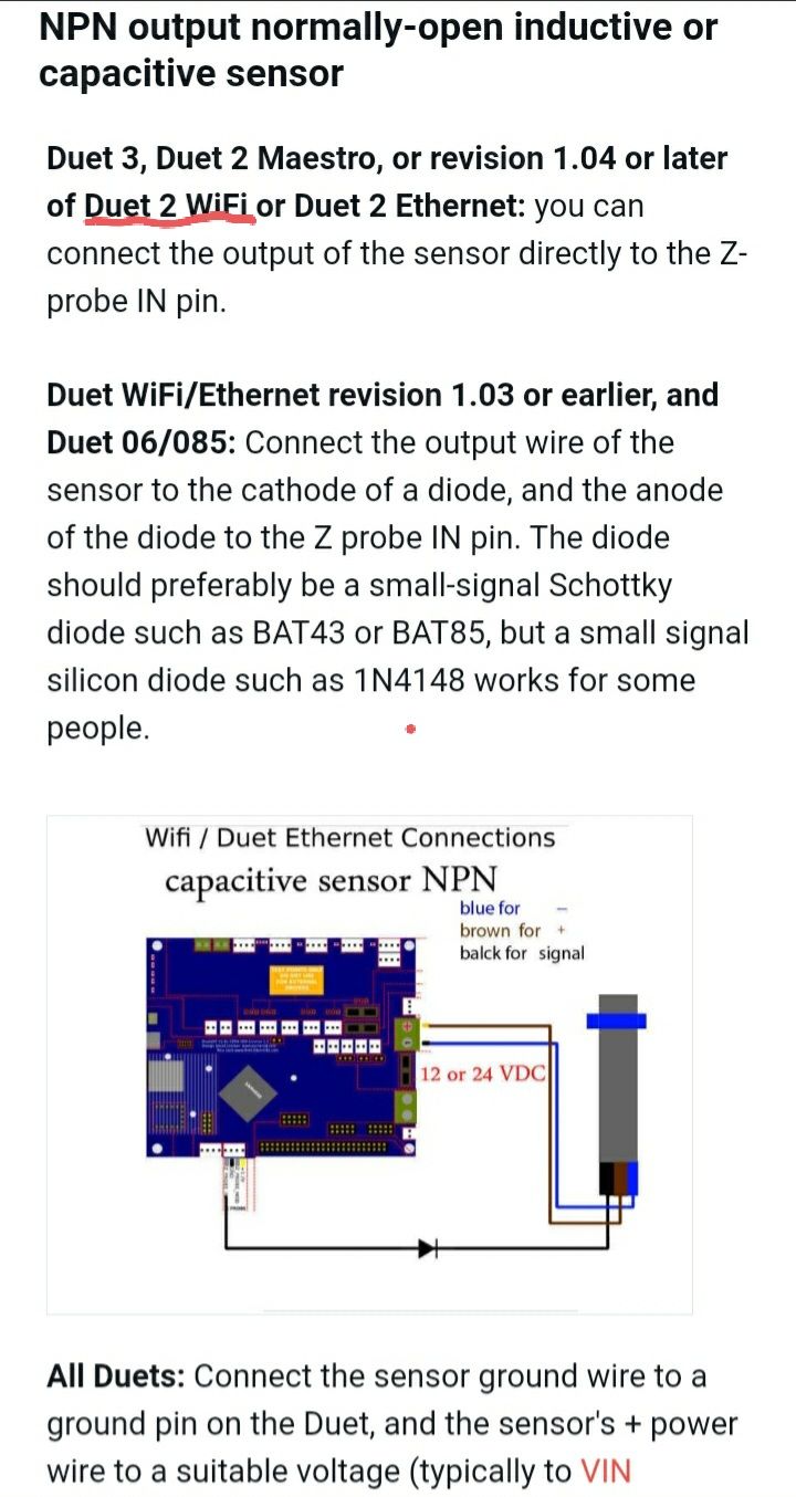
RE: Z probe as NPN inductive sensorposted in Duet Hardware and wiring
@sarvan
Looks like you don't need a diode unless your Duet2 WiFi is revision 1.03 or earlier.https://duet3d.dozuki.com/Wiki/Connecting_a_Z_probe
-
RE: Some issues configuring external stepper drivers with Duet 0.6posted in Duet Hardware and wiring
@dc42 I can check again, but since the X and Y steppers go through the motions (you can hear it quietly whine as if accelerating and decelerating just as expected with actual movement), I would think so.
I did get one of the extruder steppers actually moving (only on retract for some reason even with M302 P1) by double checking the wiring between the stepstick and stepper. Shouldn't have assumed all the steppers had the same pinout.
Edit: ooh, wait, maybe I have accidentally swapped En and Dir...
Edit2: Yup, not only had I turned the 3pin Dupont the wrong way around on the shield, I had also gotten the two rows on the confused on the Duet itself when connecting up E1 and E2. All steppers working now.
Mystery solved! Thank you.
-
RE: Some issues configuring external stepper drivers with Duet 0.6posted in Duet Hardware and wiring
Software Information
Firmware Name: RepRapFirmware for Duet
Firmware Electronics: Duet 0.6
Firmware Version: 1.26.1 (2020-02-09b1)
Web Interface Version: 1.22.6 -
RE: Some issues configuring external stepper drivers with Duet 0.6posted in Duet Hardware and wiring
@dc42 that was an easy change, but alas didnt help the issue.
Oh, and I also have watterott stepstick protectors on the silentstepsticks, might they be interfering?

-
Some issues configuring external stepper drivers with Duet 0.6posted in Duet Hardware and wiring
Hi, I have added a fabscan shield with four TMC2209 silentstepsticks to my Duet 0.6/Duet shield in the hope of more drivers with less noise in operation (yes I know, get a Duet3 already).
However, when I try to move the motors on the external drivers, they only make a sound as if they were moving but do not actually budge. Motor has holding torque, so it does receive power.
I believed I had set the currents using UART, but the trim pot on the board appears to override it. I have tried setting the currents between 0.5-1.5A without any difference in behaviour except increased holding torque and slightly louder noise.
Same motor and wiring works fine connected to the main board.
I supply the fabscan shield with +5V via the Duet and +24V externally. The Duet is powered with external 12V and external 5V via the external 12V->5V converter board
TMC2209's are hooked up to step/dir/en on the Duet expansion header.
Grateful for any pointers.
config.g :
; Configuration file for Duet 0.6 (firmware version 1.17 to 1.19) ; executed by the firmware on start-up ; ; generated by RepRapFirmware Configuration Tool v2 on Fri Aug 09 2019 23:47:07 GMT+0200 (Central European Summer Time) ; General preferences G90 ; Send absolute coordinates... M83 ; ...but relative extruder moves ; Network {Redacted} ; Drives M584 X5 Y4 Z1:2 E6:7 ; Remap X, Y, E0,E1 to external drivers. M569 P0 S0 ; Physical drive 0 goes backwards M569 P1 S1 ; Physical drive 1 goes forwards M569 P2 S0 ; Physical drive 2 goes backwards M569 P3 S0 ; Physical drive 3 goes backwards M569 P4 S0 H1 T0.1 ; Physical drive 4 goes backwards M569 P5 S1 H1 T0.1 ; Physical drive 5 goes forwards M569 P6 S1 H1 T0 1 ; Physical drive 6 goes forwards M569 P7 S1 H1 T0.1 ; Physical drive 7 goes forwards M92 X80 Y53.33 Z1600.00 E817.00:817.00 ; Set steps per mm M566 X1800.00 Y1800.00 Z12.00 E120.00:120.00 ; Set maximum instantaneous speed changes (mm/min) M203 X3000.00 Y3000.00 Z180.00 E1200.00:1200.00 ; Set maximum speeds (mm/min) M201 X9000.00 Y250.00 Z200.00 E250.00:250.00 ; Set accelerations (mm/s^2) M906 X1100.00 Y1100.00 Z800.00 E1400.00:1400.00 I30 ; Set motor currents (mA) and motor idle factor in per cent M84 S30 ; Set idle timeout ; Axis Limits M208 X-55 Y-5 Z0 S1 ; Set axis minima M208 X273 Y238 Z125 S0 ; Set axis maxima ; Endstops M574 X2 Y2 Z0 S0 ; Set active low and disabled endstops ;M574 S1 ; Set active high endstops ; Z-Probe M558 P5 I1 H5 F120 T6000 ; Set Z probe type to unmodulated, the axes for which it is used and the dive height + speeds G31 P500 X62 Y-6 Z0.7 C-0.00208 S23.5 ; Set Z probe trigger value, offset and trigger height ;Leadscrews M671 X-72:326 y0:0 S0.5 ;Set Z-leadscrew x-positions M557 X20:230 Y20:180 S35 ; Define mesh grid ; Heaters M307 H0 A103.8 C496.1 D4.0 V0.0 B0 S1.00 ; Disable bang-bang mode for the bed heater and set PWM limit and tuned PID parameters M305 P0 T100000 B4725 C7.060000e-8 R4700 ; Set thermistor + ADC parameters for heater 0 M143 H0 S120 ; Set temperature limit for heater 0 to 120C M305 P1 T100000 B4725 C7.060000e-8 R4700 ; Set thermistor + ADC parameters for heater 1 M143 H1 S290 ; Set temperature limit for heater 1 to 280C M307 H1 A419.2 C265.8 D3.2 V0.0 B0 ;Set tuned PID parameters for heater 1 M305 P3 T100000 B4725 C7.060000e-8 R4700 ; Set thermistor + ADC parameters for heater 3 M143 H3 S290 ; Set temperature limit for heater 3 to 280C M307 H3 A451.3 C269.7 D4.7 V0.0 B0 ;Set tuned PID parameters for heater 3 ; Fans M106 P0 S0 I0 F500 H-1 ; Set fan 0 value, PWM signal inversion and frequency. Thermostatic control is turned off ; Tools M563 P0 D1 H1 ; Define tool 0 G10 P0 X0 Y0 Z0 ; Set tool 0 axis offsets G10 P0 R0 S0 ; Set initial tool 0 active and standby temperatures to 0C M563 P1 D0 H3 ; Define tool 1 G10 P1 X20 Y0 Z0 ; Set tool 1 axis offsets G10 P1 R0 S0 ; Set initial tool 1 active and standby temperatures to 0C M572 D0 S1.0 ; Setup pressure advance for tool 0 M572 D1 S1.0 ; Setup pressure advance for tool 1 ; Custom settings are not configured -
RE: Dual PSU wiringposted in Duet Hardware and wiring
@Benny I'm not using a bunch of crimps between the PSUs as shown, just to terminate the wires and attach them to the PSU terminals.
Would tinned wire ends be better? Why?
-
Dual PSU wiringposted in Duet Hardware and wiring
Hi,
I'm upgrading my printer (Duet 0.6 and 12V bed, heaters etc) with some TMC2209 silentstepsticks which I intend to run on 24V.
Thus I need to wire up two PSU's.
After failing a few times to design and print a partial enclosure for the mains end of my 12V PSU and a fused mains socket and switch, I got the openbuilds powercase and a meanwell 24V PSU to go with it.Now I'm wiring them together.
Are there any immediately obvious errors or dangers in wiring them up like this?
I noticed the powercase lacks a fuse unlike my previous mains socket. Would it be necessary to wire fuses between the N and L terminals and the mains socket? Max power draw for the PSU's are 3.4A and 4A.
Should I tie V- to mains ground also on the 24v PSU or will I then get a ground loop? (Note I don't have mains ground in the socket right now, but don't want to get bitten in the ass by if when I move.) Should I instead just tie V- together between the PSU's?
