Unplugged because of that fear. I don’t have a nice, small crimp tool so those are going to be redone. Same issues with nothing plugged in but CAN and power.
Best posts made by ArcadeKilla
-
RE: Toolboard Issues Galoreposted in Duet Hardware and wiring
-
RE: Toolboard Issues Galoreposted in Duet Hardware and wiring
@samlogan87 @rjenkinsgb The only reason I claimed a firmware bug is my Toolboard is blinking 4 and 2 which indicates a firmware issue. I have the resistor bridge soldered. I will report back ASAP with the bridge cables not connected. For some reason, I got to the conclusion that the resister was simply adding to the circuit of the bridged wires, not completing the circuit without them. I really appreciate the clarification. If this works, I owe @rjenkinsgb a few beers.
Latest posts made by ArcadeKilla
-
Help Diagnosing Driver Warnings and Motor Pausesposted in Duet Hardware and wiring
Help Diagnosing Driver Warnings and Motor Pauses – Duet 6HC on RatRig VCore 3 (500mm)
Printer Setup:Controller: Duet 6HC
Motors: NEMA 17
Printer: RatRig VCore 3 (500mm)
Issue: Stepper drivers are reporting disconnection warnings, and motors randomly pause during prints/movements.
Issue Description:
I'm running a Duet 6HC on my RatRig VCore 3 (500mm) with NEMA 17 stepper motors, and I'm experiencing random pauses in motor movement, along with frequent "Driver phase may be disconnected" warnings. The motors are not even slightly warm, so I don't think it's overheating.I keep getting warnings like this:
Warning: Driver 0.4 warning: phase B may be disconnected
Warning: Driver 0.3 warning: phase A may be disconnected
Warning: Driver 0.5 warning: phase A may be disconnected
The issue affects drivers 0.3, 0.4, and 0.5 most frequently.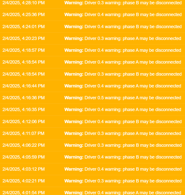
What I've Checked So Far:
Motor Wiring:Verified all stepper motor connections are secure.
Checked for any broken, loose, or frayed wires.
Swapped cables between drivers, but warnings still persist.
Duet Board:Checked for visible damage on stepper driver chips.
Ensured cooling is adequate.
Motor Resistance:Used a multimeter to measure motor coil resistance – all appear normal.
Firmware & Config:Running the latest Duet firmware.
Checked M906 and M913 settings to ensure appropriate current levels.
Questions:
What could be causing these phase A/B disconnection warnings?
Could this be a Duet 6HC hardware issue, or is it more likely a wiring problem?
Would adjusting M906 (motor current) or M913 (motor reduction during idle) help?
Has anyone else experienced similar issues with a RatRig VCore 3?
Any help is greatly appreciated!Thanks in advance!
-
RE: Replacing a Toolboard - Extruder Motor Has Never Movedposted in General Discussion
@Phaedrux
Working on this again. Here is the last iteration of my Config.G:; configuration file for Duet 3 Mini 5+ (firmware version 3.3) with Duet 3 Toolboard1LC, Rotating Magnet Filament Monitor ; executed by the firmware on start-up ; General preferences M575 P1 S1 B57600 ; enable support for PanelDue G21 ; work in millimeters G90 ; send absolute coordinates... M83 ; ...but relative extruder moves M550 P"duet3" ; set printer name M669 K1 ; select CoreXY mode ; Tool board (CAN ID #121) G4 S6 ; wait for tool board to start ; PanelDue Enable M575 P1 S1 B57600 ; Network M552 S1 ; enable network M586 P0 S1 ; enable HTTP M586 P1 S0 ; disable FTP M586 P2 S0 ; disable Telnet ; Drives M569 P0.0 S0 D3 ; physical drive 0.0 goes forwards use stealthChop2 M569 P0.1 S0 D3 ; physical drive 0.1 goes forwards use stealthChop2 M569 P0.2 S0 D3 ; physical drive 0.2 goes forwards use stealthChop2 M569 P0.3 S1 D3 ; physical drive 0.3 goes forwards use stealthChop2 M569 P0.4 S1 D3 ; physical drive 0.4 goes forwards use stealthChop2 M569 P121.0 S1 D3 ; physical drive 121.5 goes forwards use stealthChop2 M584 X0.4 Y0.3 Z0.0:0.1:0.2 E121.0 ; set drive mapping M350 X16 Y16 Z16 E16 I1 ; configure microstepping with interpolation M92 X80.00 Y80.00 Z800.00 E830.00 ; set steps per mm M566 X400.00 Y400.00 Z6.00 E120.00 P1 ; set maximum instantaneous speed changes (mm/min) M203 X10800.00 Y10800.00 Z1000.00 E3600.00 ; set maximum speeds (mm/min) M201 X3000.00 Y3000.00 Z100.00 E3600.00 ; set accelerations (mm/s^2) M906 X1000 Y1000 Z800 E800 I30 ; set motor currents (mA) and motor idle factor in percent M84 S30 ; Set idle timeout ; Axis Limits M208 X0 Y0 Z0 S1 ; set axis minima M208 X505 Y500 Z500 S0 ; set axis maxima ; Endstops M574 X1 S1 P"121.io2.in" ; configure switch-type (e.g. microswitch) endstop for high end on X via pin io2.in on toolboard M574 Y2 S1 P"io6.in" ; configure switch-type (e.g. microswitch) endstop for high end on Y via pin io6.in M574 Z1 S2 ; configure Z-probe endstop for low end on Z ; Z-Probe M950 S0 C"121.io0.out" ; create servo pin 0 for BLTouch on tool board M558 P9 C"121.io0.in" H5 F120 T6000 A5 ; set Z probe type to bltouch and the dive height + speeds on tool board G31 P500 X-40 Y-30 Z0.9 ; set Z probe trigger value, offset and trigger height M671 X-4.5:250:500 Y-4.52:500:-4.52 S5 ; define positions of Z leadscrews, 5mm maximum correction M557 X20:280 Y20:280 P5 ; define 5x5 mesh grid ; Bed Heater M308 S0 Q10 P"temp0" Y"thermistor" T100000 B3950 A"Bed" ; configure sensor 0 as thermistor on pin temp0 M950 H0 C"out0" T0 ; create bed heater output on out1 and map it to sensor 0 M307 H0 B0 S1.00 ; disable bang-bang mode for the bed heater and set PWM limit M140 H0 ; map heated bed to heater 0 M143 H0 S120 ; set temperature limit for heater 0 to 120C ; Mosquito Magnum+ Separate Heaters Single Tool (Two Sensors) ; Two Temperature Sensors M308 S1 P"temp2" Y"pt1000" A"RightTemp" ;Pt1000 located in right side of hot block M308 S2 P"temp1" Y"pt1000" A"LeftTemp" ;Pt1000 located in left side of hot block ; Define Mosquito Magnum+ heaters M950 H1 C"out2" T1 ;Single Heater M950 H2 C"out3" T1 ;Second Heater ; Define Monitor Temperature Sensor M143 H1 P1 S450 T2 A0 M143 H2 P1 S450 T2 A0 ;Mosquito Magnum+ Max Temperatures M143 H1 S450 M143 H2 S450 ;Tool Definition Mosquito Magnum+ ;M563 P0 D0 H1:2 S"Mosquito Magnum+" F1 ;Define Mosquito Magnum+ Tool ;T0 ;Set tool 0 as active tool ;G10 P0 S0:0 R0:0 ;Set tool operating and standby temperatures ;; Run Bed PID Tune!! Below is an example for a 300x300 bed ;; M307 H0 A303.1 C356.7 D1.4 S1.00 V24.0 B0 ;; Run Heater PID Tune!! ;; M307 H1 A751.5 C196.6 D4.7 S1.00 V23.9 B0 ; Fans M950 F0 C"out4" Q300 ; create fan 0 on pin out1 on tool board and set its frequency M106 P0 C"Watercooling Fan" S1 H1 T45 ; set fan 0 value. Thermostatic control is turned on M950 F1 C"121.out2" Q500 ; create fan 1 on pin out2 on tool board and set its frequency M106 P1 C"Layer Fan" S1 H-1 ; set fan 1 value. Thermostatic control is turned off ; Tools M563 P0 S"Mosquito Magnum+" D0 H1:2 F1 ; define tool 0 with extruder drive 0 heater 1 and fan 1 G10 P0 X0 Y0 Z0 ; set tool 0 axis offsets G10 P0 R0 S0 ; set initial tool 0 active and standby temperatures to 0C M302 S180 R180 ; allow extrusion starting from 180C and retractions already from 180C ; Accelerometer M955 P121.0 I12 ; Accelerometer on tool board, oriented counter-clockwise 90 ; Filament Monitor M591 D0 P3 C"121.io1.in" S1 R70:130 L24.8 E3.0 ; Duet3D rotating magnet sensor for extruder drive 0 is connected to io1.in on tool board, ; enabled, 70% to 130% tolerance, sensitivity 24.8mm.rev, 3mm detection length ; Custom settings M404 N1.75 D0.4 ; set filament width and nozzle diameter T0 ;Set tool 0 as active tool -
RE: Replacing a Toolboard - Extruder Motor Has Never Movedposted in General Discussion
I’ll find my config but when I was testing I was manually running commands to test the extruder. Even when not attached to the hotend it was not working.
-
RE: Replacing a Toolboard - Extruder Motor Has Never Movedposted in General Discussion
@phaedrux (https://forum.duet3d.com/topic/26885/so-close-extruder-connected-to-toolboard-won-t-budge?_=1665495044262)
As of now, no luck. Maybe I can use one of the mainboards stepper drivers to confirm the extruder drive works.
-
Replacing a Toolboard - Extruder Motor Has Never Movedposted in General Discussion
What is warranty like? I have no successfully been able to get my Toolboard to move my extruder motor at all.
-
RE: So close...Extruder connected to Toolboard won't budge.posted in Duet Hardware and wiring
@dc42 Windings are correct. Plug seems good enough after re-crimping. Going to attempting to see if it will drivee a different stepper. How do I get the toolboard warrantied if it is dead? It's the only thing keeping this machine from running.
-
RE: So close...Extruder connected to Toolboard won't budge.posted in Duet Hardware and wiring
Wiring looks as pretty good.
M98 P"config.g" Error: M552: Network-related commands are not supported when using an attached Single Board Computer CORS disabled CORS disabled CORS disabled Accelerometer 121:0 with orientation 12 samples at 1344Hz with 10-bit resolution -
RE: So close...Extruder connected to Toolboard won't budge.posted in Duet Hardware and wiring
Alright! Doing a lot better. I am getting communication and no errors now. Only issue now is I am only getting vibrations and no movement from any extruder commands.
-
RE: So close...Extruder connected to Toolboard won't budge.posted in Duet Hardware and wiring
@phaedrux I ended up redoing the firmware as I was having communication issues. This might be the source of my issues.
-
RE: So close...Extruder connected to Toolboard won't budge.posted in Duet Hardware and wiring
@rjenkinsgb Sadly, 'black and green' and 'red and green' are the correct connections. Just tested
