@droftarts Thanks to both of you p2 worked for me.
Posts made by Ambros
-
RE: Filament sensor not shown by M119 commandposted in General Discussion
-
Filament sensor not shown by M119 commandposted in General Discussion
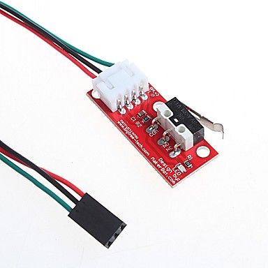
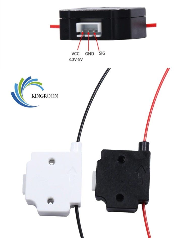
Hi everyone, I need help to set up Filament sensor for my machine. I am using a normal limit switch for that shown in the image. I tried all of the settings which I found on the forum but no luck. I am using 2.05 firmware. These are the commands I tried. I change the wire orientation since it's on the wrong side on the opposite end. The red one I used to check whether the limit switch is ok or not.

; Endstops
M574 X1 Y1 Z0 E1 S0
; Filament runout sensor
M591 D1 P1 C3M591 D0 P1 C3 S1
M581 E1:2 S1 T2 C1
M591 P3 C"e0_stop" S1
M591 P3 C"e0_stop" S0
All the commands show same result of not detecting the sensor
-
RE: E1 Extruder heater not able to provide constant current.posted in General Discussion
@dc42 Sir as you described I correct the parameters but Laser is not turning on. I think I made a wrong connection with the laser to board. In my case what I did is I connected vin and ground directly to the E1. Since the laser is 12 volt so I attach a L7812cv transistor which converts 24v to 12v. The link below is the laser I have, can you please give me direction on how to attach it to the mainboard.
https://www.aliexpress.com/item/32801509554.html?spm=a2g0s.9042311.0.0.DZ4FEn
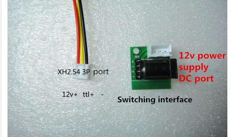
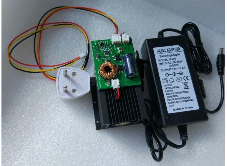
I just made a direct connection of laser with duet board with that transistor to avoid overvoltage. Kindly provide some direction of how to install properly with E1. Did I also need any other components to run this?
-
RE: E1 Extruder heater not able to provide constant current.posted in General Discussion
@Phaedrux yes I already set it as you described, but don't know when I put M452 in the laser config file, machine did not perform any homing cycle of laser and if I change it to M453 then there is no issue in homing. Every macro work without giving any error. But E1 not able to provide constant current to laser which is around 2 amp.
At this location
M307 H2 A-1 C-1 D-1 ; Set E1 Heater logic to laser
M453 P2 I0 R255 F200 ; Set Laser Mode E1 Heater
M563 P2 S"Laser" ; Assign Laser to tool 2
Dont know why it create problem with M452. Dear in the above config file did you find any flaw. -
RE: E1 Extruder heater not able to provide constant current.posted in General Discussion
@aidar With M452 it gives an error G0/G1 insufficient axis are homed. I read a post by dc42 where he mentioned someone to use M453 and I use it and it worked. Also when I wrote M452 in config.g I am no longer been able to use my macros settings becasue I build a 3 in 1 cnc and I am using differen tmacros to swap the settings but with M452 I am no longer been able to use any of those macros(it says Response to long, See Console)
-
E1 Extruder heater not able to provide constant current.posted in General Discussion
Hi everyone< I have been working on a machine with duet wifi board and I am currently using E0 for extruder heater and I want to use E1 heater for Laser module. I am using a 15-watt laser module. The problem is that if I made a direct connection to laser with a 12v adapter there is no problem, but If I connect it to E1 point of the board first it's fired up but after 10 sec it's not even able to penetrate from paper and when I measure the current it fist showed around 1.6 amps and then gradually starts decreasing and stops at .350amp. Cant able to understand what's wrong. I am using M3 S255 command to on the laser. The first hole took 5 sec to complete 5 mm thick acrylic but from thereafter it's not even able to burn a paper and the current reached at .330-380 amp. M452 giving me some error so that's why I am using M453. Down below is my config file and I am using 2.05 version of firmware. Please help
; Configuration file for Duet WiFi (firmware version 2.05)
; executed by the firmware on start-up
;
; generated by RepRapFirmware Configuration Tool v2.0.4 on Wed Oct 16 2019 02:43:19 GMT-0700 (Pacific Daylight Time); General preferences
G90 ; send absolute coordinates...
M83 ; ...but relative extruder moves
M550 P"laser" ; set printer nameNetwork M552 S1 ; enable network
M586 P0 S1 ; enable HTTP
M586 P1 S0 ; disable FTP
M586 P2 S0 ; disable Telnet; Drives
M569 P0 S1 ; physical drive 0 goes forwards
M569 P1 S1 ; physical drive 1 goes backwards
M569 P2 S0 ; physical drive 2 goes backwards
M569 P3 S0 ; physical drive 3 goes forwards
M584 X0 Y1 Z2 E3 ; set drive mapping
M350 X16 Y16 Z16 E16 I1 ; configure microstepping with interpolation
M92 X21.32 Y21.32 Z805.09 E420 ; set steps per mm
M566 X900.00 Y900.00 Z12.00 E120 ; set maximum instantaneous speed changes (mm/min)
M203 X9000.00 Y9000.00 Z600.00 E1200 ; set maximum speeds (mm/min)
M201 X400.00 Y400.00 Z50.00 E250.00 ; set accelerations (mm/s^2)
M906 X2400 Y2400 Z1600 E55 I100 ; set motor currents (mA) and motor idle factor in per cent
M84 S30 ; Set idle timeout; Axis Limits
M208 X0 Y0 S1 ; set axis minima
M208 X370 Y500 Z750 S0 ; set axis maxima; Endstops
M574 X1 Y1 Z1 S0 ; set active low and disabled endstops; Z-Probe
M574 Z1 S2 ; set endstops controlled by probe
M307 H3 A-1 C-1 D-1 ; disable heater on PWM channel for BLTouch
M558 P3 H3 F200 T7200 ; set Z probe type to bltouch and the dive height + speeds
G31 P500 X0 Y0 Z1.05 ; set Z probe trigger value, offset and trigger height
M557 X0:300 Y15:635 S50 ; define mesh grid; Laser
M307 H2 A-1 C-1 D-1 ; Set E1 Heater logic to laser
M453 P2 I0 R255 F200 ; Set Laser Mode E1 Heater
M563 P2 S"Laser" ; Assign Laser to tool 2
G10 P3 X50 Y0 Z0 ; Laser axis offset; BLTouch - Heaters
M307 H3 A-1 C-1 D-1 ; Disable the 7th Heater to free up PWM channel 5 on the Duex board.; Fans
M106 P0 S0 I0 F500 H-1 ; set fan 0 value, PWM signal inversion and frequency. Thermostatic control is turned off
M106 P1 S1 I0 F500 H1 T45 ; set fan 1 value, PWM signal inversion and frequency. Thermostatic control is turned on; Tools
M563 P0 D0 H1 F0 ; define tool 0
G10 P0 X0 Y0 Z0 ; set tool 0 axis offsets
G10 P0 R0 S0 ; set initial tool 0 active and standby temperatures to 0C; Custom settings are not defined
I have no problem in turning on and off of laser during cutting but the only problem is that the current decrease so much that it wasn't able to cut paper even at ultra slow speed. Laser is absolutely fine there is no problem with that. Previously connected to fan port but it blows the fuse. so dont want to take risk again. If I install bigger fuse do you think its ok for board. The laser uses 2amps of current when its working.
-
RE: How to setup bltouch and Z touch plate for 3 in 1 cnc.posted in General Discussion
@droftarts You are a true master and I am really thankful to you, Can't able to express my feelings. You and all the people helped a lot and huge thanks to all of you. Especially you and dc42. Extremely happy now.
-
RE: How to setup bltouch and Z touch plate for 3 in 1 cnc.posted in General Discussion
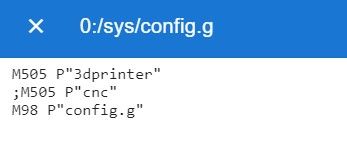
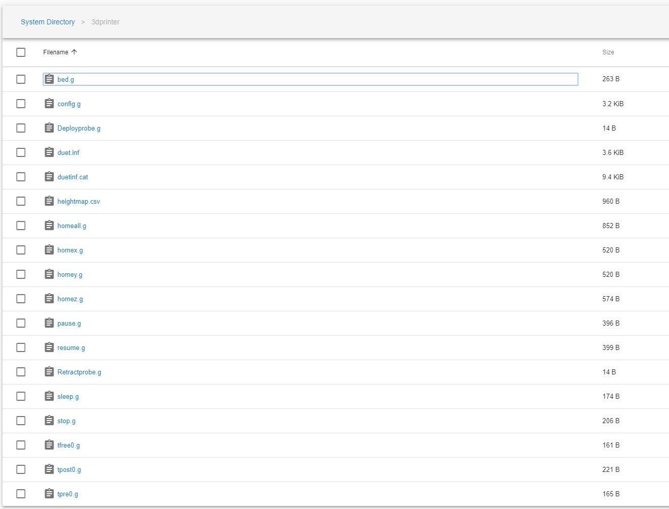
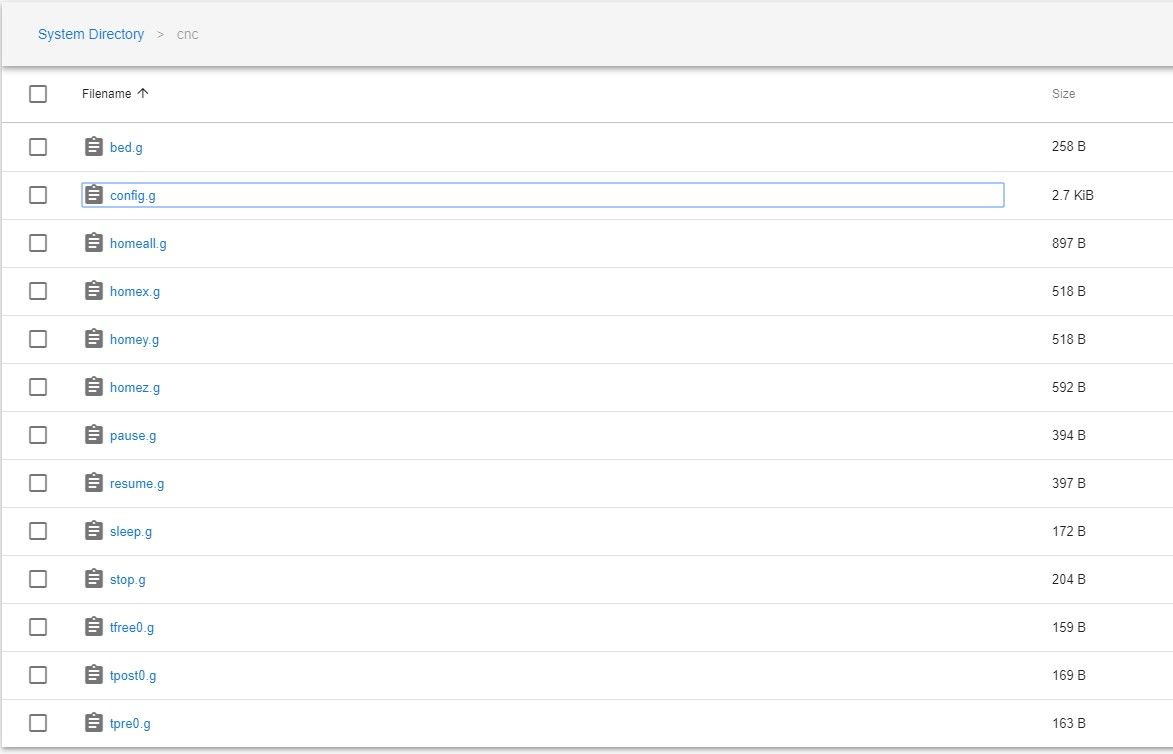
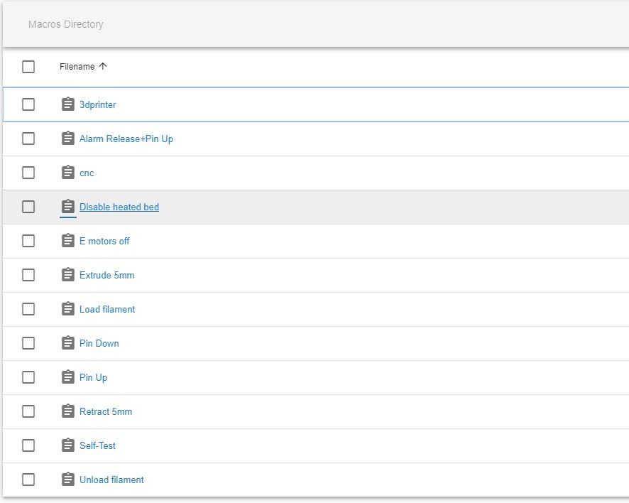
@droftarts So here are the screenshot of the different directory

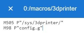
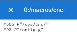
-
RE: How to setup bltouch and Z touch plate for 3 in 1 cnc.posted in General Discussion
@droftarts so besides that reason there is no other reason for this error because after reading your message I double-check and still the same problem.
-
RE: How to setup bltouch and Z touch plate for 3 in 1 cnc.posted in General Discussion
@droftarts @dc42 Hi dear, you are correct about the macro and now I am successfully able to switch but the problem is that when I switch to 3dprinter it's accomplished without any error but if I switch to CNC it again says
macro file config.g not found.
So to sort out this problem I flash the sd card and upload the config files of both cnc and 3dprinter. but error remains the same (able to switch to 3d printer but not to the cnc)
Then I put the same types of files in both the folders(I mean the 3dprinter files which are successfully loaded by the duet) but issue remains the same.
I also change the folder name to something different like a router, cncrouter etc. but the issue remains the same.
I also give first preference to cnc in config.g file which is
M505 P"cnc"
; M505 P"3dprinter"
M98 P"config.g"
But same issue again.
Dont know why it wasn't able to load that second folder files. It always says(macro file config.g not found.)
During all these changes I also change the name in config.g file which is in sys folder and names in the macros as well, but still facing the same issue. The machine have no problem in switching back to printer mod but during the cnc mod, it says that line and I wasn't able to do anything.I am not able to understand if two folders have same files inside them then why it gives error in one case and not in other.
-
RE: How to setup bltouch and Z touch plate for 3 in 1 cnc.posted in General Discussion
@dc42 Sir now with that file setup the machine is able to load the printer settings, but the problem is that when I use the macro to use CNC files I got an error and it says
macro file config.g not found.
can you please tell what wrong I did. The macro file name is cnc and inside that the code is
M505 P"cnc"
M98 P"config.g"
One thing I noticed in the 3dprinter folder that there it a folder created by itself named cnc" and this is the correct notation I wrote. And inside this folder, if I open again and again seven times then a file name config-override.g shows and it says that its a computer generated file. But if I gave cnc to first problem it says macro file config.g not found, even though it still present inside that folder with everything properly written inside them. -
RE: How to setup bltouch and Z touch plate for 3 in 1 cnc.posted in General Discussion
@droftarts An apology for my dumb question. what you are saying is that after making two different folders of 3d printer and CNC and putting only config file. In the main sys folder, I need to create a config.g file and put the code.
M505 P"3D printer"
; M505 P"CNC”
M98 P"config.g"And that's all.
One more thing I wanted to know that if you take a look on homeall.g, homex.g, homey.g and homez.g file and few more files as well they have code written inside them. But since in my CNC I am using a limit switch to zero the z-axis and in my main folder, the file homeall.g and homez.g doesn't contain any parameter to use those limit switch. Did i need to put any separate file for them? Or I need to put all the files inside those folders which I created named CNC and 3d printer and in the main folder, there is only custom config.g file. And there are only 3 files shown in main system folder CNC, 3d printer folder and a config.g file and that's all I need. Which one is correct. down below I made a file structure in the main folder kindly suggest which one is correct.File structure in sys mains folder
3d printer(with all the files)
CNC (with all the files)
Config.g(which created custom having those three parametre)or
3d printer(only the config.g)
CNC (only the config.g)
Config.g(which created custom having those three parametres)
bed.g
deployprobe.g
homeall.g
homex.g
homey.g
homez.g
pause.g
resume.g
resurrect.g
sleep.g
retractprobe.g
stop.g
tfree0.g
tpost0.g
tpre0.g -
RE: How to setup bltouch and Z touch plate for 3 in 1 cnc.posted in General Discussion
@dc42 Sir can you tell the structure of those files here because I tried and not able to switch the files. To me, it seems that I am doing something wrong because I am not able to understand the structure. What I did is that in the main folder I made two folders 3d printer and CNC and then I put config.g file in that folder one having CNC settings other having 3d printer settings. And then in macro, I create two files named CNC and 3dprinter and inside them, I wrote M505 P3dprinter M98 Pconfig.g and M505 Pcnc M98 Pconfig.g but its gives error says unable to locate config.g. I am not able to understand the whole thing first I thought ahhh... got the point and then it's just lost completely......................... can you write here that structure please. Thanks.....
-
RE: How to setup bltouch and Z touch plate for 3 in 1 cnc.posted in General Discussion
@Phaedrux Thanks to both of you guys for helping, Currently printing a big print on the machine and it's going to take 34hr to print but after that follow this method and tells the report. Again thanks
-
RE: How to setup bltouch and Z touch plate for 3 in 1 cnc.posted in General Discussion
@Veti so what you are saying is that if i put these code in start and end of any program that will automatically active that limit switch which i want to triggered.
;Endstops
M574 X1 Y1 Z1 S0 ; set active low and disabled endstops; Z-Probe
M574 Z1 S2 ; set endstops controlled by probe
M307 H3 A-1 C-1 D-1 ; disable heater on PWM channel for BLTouch
M558 P3 H3 F200 T7200 ; set Z probe type to bltouch and the dive height + speeds
G31 P500 X0 Y0 Z.9 ; set Z probe trigger value, offset and trigger height
M557 X0:300 Y15:635 S50 ; define mesh gridSo the above-written thing is my current setting for end stops in the config file. What I want to say is that during RepRap configurator tool if you select both probe and limit switch then it creates this type of program which written above about the end stops. So If this code is generated then why this doesn't active both the switches. Or did I understand wrong about what written in the config file. becasue in the homez.g file the program is entirely different about using Z probe and limit switch.
For Limit switch homez.g is
; homez.g
; called to home the Z axis
;
; generated by RepRapFirmware Configuration Tool v2.1.3 on Sun Dec 08 2019 19:52:09 GMT+0530 (India Standard Time)
G91 ; relative positioning
G1 H2 Z5 F6000 ; lift Z relative to current position
G1 H1 Z-755 F1800 ; move Z down until the endstop is triggered
G92 Z0 ; set Z position to axis minimum (you may want to adjust this); Uncomment the following lines to lift Z after probing
;G91 ; relative positioning
;G1 H2 Z5 F100 ; lift Z relative to current position
;G90 ; absolute positioningFor Z-probe its
; homez.g
; called to home the Z axis
;
; generated by RepRapFirmware Configuration Tool v2.0.4 on Wed Oct 16 2019 02:43:19 GMT-0700 (Pacific Daylight Time)
G91 ; relative positioning
G1 Z5 F7200 S2 ; lift Z relative to current position
G90 ; absolute positioning
G1 X62 Y15 F7200 ; go to first probe point
G30 ; home Z by probing the bed; Uncomment the following lines to lift Z after probing
;G91 ; relative positioning
;G1 S2 Z5 F120 ; lift Z relative to current position
;G90 ; absolute positioningSo isn't there any way to merge both of these files and tell the machine that chose one which triggered first and registered Z on the bases of that switch.
-
RE: How to setup bltouch and Z touch plate for 3 in 1 cnc.posted in General Discussion
@Veti but then it became a nightmare for me if i have to change the configuration again and again. And I really dont have any idea regarding the script. If you can help then I would be thankful to you.
-
RE: How to setup bltouch and Z touch plate for 3 in 1 cnc.posted in General Discussion
@fcwilt Dear my purpose is that if I am working on 3d printer side I use Bltouch sensor and if I use CNC router I am able to use a limit switch or any other type of switch which helps to zero the CNC router when a bit is installed. Although touch plate is mostly used in CNC router to zero the z-axis, Setup is made like a gator clip attached to the router bit which also connected to the plate as well. Here is the link showing about touch plate.
-
RE: How to setup bltouch and Z touch plate for 3 in 1 cnc.posted in General Discussion
please tell me, dear, if there is anything, is it possible to create a macro and then home the z-axis according to those macros, if yes then can you tell those. I mean if I auto home x and y and leave the z and then home z from those macros. Is it possible if yes then how? thanks


 This is my setup