@dc42 Never connect the input of a DC-DC converter to a heater or fan output. - I did exactly that, what might be consequences?
I will follow your advice, thanks for letting me know.
@dc42 Never connect the input of a DC-DC converter to a heater or fan output. - I did exactly that, what might be consequences?
I will follow your advice, thanks for letting me know.
I guess I got lucky, 1st rule of engineering: If it ain't broke, don't fix it
Yes S1 and S0 works for me but Led it too bright I needed to dim it.
Anyways got this issue solved, I added step down DC converter between Duet and Led, now flickering is gone.
@bearer I tried all sorts of PWM values, I don't really need to dim them but I have to be able to turn it on and off with G-code commands. And I don't have any driver after duet, just a resistor
@taconite I cannot have this LED always on, I need to be able to switch in on and off with m106 commands.
I'm using duet wifi to build pick and place machine with bottom vision camera and led ring around it.
I have problem with horizontal lines on camera image and I suspect it might be caused by Led controlled by PWM from Fan2 output.
Is there any way to switch off PWM on fan and just have plain voltage control instead?
Thanks
Arkadiusz
@Veti I just printed calibration cube and it came out 3.5mm too short, missing bottom layers.
Z axis doesn't work until it reaches offset height I setup on E1: G10 P1 X0 Y0 Z3.5 U0
edit:
I removed offset from G10 command and instead in Cura in extruder2 start g-code I added:
G1 Z3.5
G92 Z0
This did the trick, now I have to find way to implement it in duet config file. It works fine but I prefer to not rely on Cura to execute this command.
You're right, adjusting offset on E1 doesn't mess printer in the way E0 does.
I swapped connections between E0 and E1 and it works fine now thanks.
Its very weird that E0 does this, I took me a while to figure out it was Z offset on E0 causing that.
Hi,
I have dual extruder setup where one of them is lifting up when second extruder is used.
So E0 is low and moves up when E1 is used by moving U axis, therefore there need to be 3.5mm offset on Z axis for E0
I tried to implement Z offset in config.g using G10 P0 X0 Y0 Z3.5 U0 - it worked for offset but messed my printer and it Z axis wouldn't move during print anymore, printing only using X and Y axis.
Is there any other way I can implement this offset? I'm very basic with gcode.
Pcb breakout board for stepper driver arrived, this solved my issue.
@dc42 said in External stepper driver, motor hissing:
G91 G1 H2 U50
M564 S0 H0 worked to disable xyz endstop so It also should work for U axis.
I tried G91 G1 H2 U50 but it there was no difference.
I'm awaiting delivery of new driver with carrier pcb that includes capacitor and dip switches for microstepping. Hopefully there is something missing in my setup that pcb will fix.
@Veti Thanks for pointing that out. Now I hope someone knows answer to my main question.
@Veti
It worked for me so far, so did drivers just run all this time at its maximum interpolation of x16? If I change it to x16 do I have to adjust steps?
Hello,
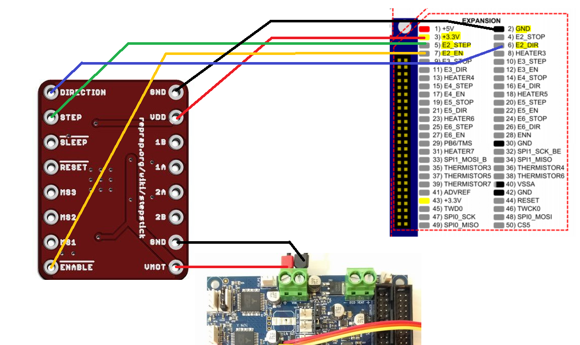
I'm trying to add additional U axis to my 3d printer using E2 on expansion board. As external drive I used A4988 stepper driver.
I got everything wired up, I created U axis which seems to work but whenever I try to move motor it wont and instead makes high pitch hissing noise. When I touch shaft there is a bit torque but very little. I tried different A4988 drivers as well as different kind (which I cannot identify) with same result. Motor is also fine as I tested It on E0 driver, I also used M564 S0 H0 command to disable endstops.
Here is my wiring, maybe there is something that I missed (except for stepper motor )
Please free to criticize my code as I'm not sure if my stepping is correct. It works for me so far.
edit
I lowered number of steps on U axis and now motor behave differently. It still doesn't work but motor makes small movement back and forth like when you wire it incorrectly.
I'm pretty sure I have coils wired correctly but I tried different combinations just in case.
I ordered new genuine Pololu a4988 driver and breakout board for it, I hope it will help.
; Drives
M569 P0 S0 ; physical drive 0 goes backward
M569 P1 S0 ; physical drive 1 goes forwards
M569 P2 S1 ; physical drive 2 goes forwards
M569 P3 S0 ; physical drive 3 goes forwards
M569 P4 S0 ; physical drive 4 goes forwards
M569 P5 S0 ; physical drive 5 goes forwards
M584 X0 Y1 Z2 U5 E3:4 ; set drive mapping
M350 X16 Y16 Z16 U16 E16:16 I1 ; configure microstepping with interpolation
M92 X145.25 Y145.25 Z717.5 U5 E425:425 ; set steps per mm
M566 X1500.00 Y1500.00 Z12.00 U120 E120.00:120.00 ; set maximum instantaneous speed changes (mm/min)
M203 X6000.00 Y6000.00 Z1500 U60 E1200.00:1200.00 ; set maximum speeds (mm/min)
M201 X1000.00 Y1000.00 Z200.00 U60 E250.00:250.00 ; set accelerations (mm/s^2)
M906 X1500 Y1500 Z1500 U1200 E1200:1200 I20 ; set motor currents (mA) and motor idle factor in per cent
M84 S30 ; Set idle timeout
; Axis Limits
M208 X0 Y0 Z0 U0 S1 ; set axis minima
M208 X320 Y320 Z330.3 U50 S0 ; set axis maxima
; Endstops
M574 X1 Y1 Z2 U1 S0 ; set active high endstops
I tried Dwell but its too "robotic", Its hard to achieve smooth movement. Looks like there is no such setup available on Duet at this moment. I ended making external servo controller using servo testers.
Cheers
I was thinking about this solution, but I need to move servo with single macro button.
I could pack macro with loads of individual M280 commands but I'm not sure how to set delay.
Hello,
I assigned servo to unused fan I/O pins using M42 command, then I managed to move servo to desired position using M280.
However servo is moving at its top speed. Is there any extra command that can be added to M280 in order to slow down the servo?
Cheers
Thanks for help everyone, I'm still beginner here and I appreciate all help provided.
Like bearer and Phaedrux said I had to modify config.g.