Duet3D Logo Duet3D
    • Tags
    • Documentation
    • Order
    • Register
    • Login
    1. Home
    2. Bart1992
    • Profile
    • Following 0
    • Followers 0
    • Topics 3
    • Posts 10
    • Best 2
    • Controversial 0
    • Groups 0

    Bart1992

    @Bart1992

    2
    Reputation
    1
    Profile views
    10
    Posts
    0
    Followers
    0
    Following
    Joined Last Online

    Bart1992 Unfollow Follow

    Best posts made by Bart1992

    • RE: Configure multiple bed heaters

      @phaedrux Thanks for your response

      As requested :

      Duet firmware version : 2.05
      DWC version : 2.07

      M122 output :
      ( had to do it like this, otherwise it's marked as spam? )

      m122output.txt

      M98 P"config.g" output :

      M98 P"config.g"
      HTTP is enabled on port 80 FTP is disabled TELNET is disabled Warning: Heater 6 appears to be over-powered. If left on at full power, its temperature is predicted to reach 365C. Error: M106: Fan 2 is disabled Error: M106: Fan 3 is disabled Error: M106: Fan 4 is disabled Error: M106: Fan 7 is disabled Error: M106: Fan 8 is disabled
      
      posted in Tuning and tweaking
      Bart1992undefined
      Bart1992
    • Configure multiple bed heaters

      Hi,

      I'm trying to configure a multiple bed heaters setup, however i'm not succeeding in getting the bed heaters to show up in the DWC and Paneldue.

      My specific heater config looks like :

      ; Heaters___________________________________________________________
      
      ; Bed1 parameters 
      M140 P0 H0
      M305 P3 S"Bed1" X150 T"J"  ; Set thermocouple heater 0 = bed 1 thermocouple = J type 
      M143 H0 S125 ; Set temperature limit for heater 0 to 125C
      
      ; Bed2 parameters 
      M140 P3 H6
      M305 P3 S"Bed2" X151 T"J"  ; Set thermocouple heater 0 = bed 1 thermocouple = J type 
      M307 H6 B1 S1.00
      M143 H6 S125 ; Set temperature limit for heater 0 to 125C
      
      ; Bed3 parameters 
      M140 P4 H7
      M305 P3 S"Bed3" X152 T"J"  ; Set thermocouple heater 0 = bed 1 thermocouple = J type 
      M307 H6 B1 S1.00
      M143 H6 S125 ; Set temperature limit for heater 0 to 125C
      
      ;E0_________________________________________________________________
      M305 P1 T100000 B4725 C7.060000e-8 R4700                     	    ; Set thermistor + ADC parameters for heater 1
      M143 H1 S285                                                        ; Set temperature limit for heater 1 to 285C
      
      ;E1_________________________________________________________________
      M305 P2 T100000 B4725 C7.060000e-8 R4700                       	    ; Set thermistor + ADC parameters for heater 2
      M143 H2 S285                                                        ; Set temperature limit for heater 2 to 285C


      and for completion, the complete config looks like :

       
      ; General preferences_______________________________________________
      G90                                          				; Send absolute coordinates...
      M83                                         				; ...but relative extruder moves
      M111 S0 													; Debug off
      M555 P2 													; Set output to look like Marlin
      M575 P1 B57600 S1											; Set auxiliary serial port baud rate and require checksum (for PanelDu
      
      ; Network________________________________________________________ֹֹֹֹֹ___
      M550 P"Big Meter - Kverneland Group"                          							; Set machine name
      ;M551 P"MODIX3D"               										; Set password (optional)
      M552 S1                                 							; Enable network
      ;M552 P0.0.0.0														; Uncomment this command for using Duet Ethernet board
      M586 P0 S1                                							; Enable HTTP
      M586 P1 S0                               					    	; Disable FTP
      M586 P2 S0                                							; Disable Telnet
      
      ; Drives
      ;Main board______________________________________________________________________
      M569 P0 S0                                                     		; Physical drive 0 . X1
      M569 P1 S1                                                       	; Physical drive 1 . X2
      M569 P2 R-1                                                        	; Physical drive 2 . Canceled
      M569 P3 S1                                                       	; Physical drive 3 . Main Extruder
      M569 P4 S0                                                       	; Physical drive 4 . Secondery Extruder
      ;Duex5 board_____________________________________________________________________
      M569 P5 S0                                                       	; Physical drive 5 . Y
      M569 P6 S0                                                       	; Physical drive 6 . Z1 (0,1000) 
      M569 P7 S0                                                       	; Physical drive 7 . Z2 (0,0) 
      M569 P8 S0                                                       	; Physical drive 8 . Z3 (1000,0) 
      M569 P9 S0                                                       	; Physical drive 9 . Z4 (1000,1000) 
      ;___________________________________________________________________ 
      M584 X0:1 Y5 Z6:7:8:9 U1 E3:4 P3									; Driver mapping
      M671 X-181:-181:1049:1049 Y1066:-58:-58:1066 S10    			  	; Anticlockwise 
      ;___________________________________________________________________
      M350 X16 Y16 Z16 E16:16 U16 I1                                		; Configure microstepping with interpolation
      M92 X100.00 Y100.00 Z2000.00 E440.530:418.500 U100.00      			; Set steps per mm
      M566 X240 Y360 Z30.00 E120.00:120.00 U240 P1                    	; Set maximum instantaneous speed changes (mm/min)
      M203 X9000.00 Y9000.00 Z200.00 E1200.00:1200.00 U9000.00    		; Set maximum speeds (mm/min)
      M201 X1000 Y1000 Z120.00 E250.00:250.00 U1000             			; Set accelerations (mm/s^2)
      M204 P500                                      						; Set print and travel accelerations  (mm/s^2)
      M906 X1800 Y1800.00 E1000.00:1000.00 U1800 I40 						; Set motor currents (mA) and motor idle factor in per cent
      M906 Z1800.00 I50 													; Set motor currents (mA) and motor idle factor in per cent
      M84 S60 X Y U E0 E1                                                 ; Set idle timeout - one minute
      
      ; Axis Limits_______________________________________________________
      M208 X0:1000 Y0:1000 Z0:1000 U0:1000		                        ; Set axis minima and maxima
      
      ; Endstops__________________________________________________________
      M574 X1 Y2 U1 S1                                            		; Set active low and disabled endstops
      	
      ; Z-Probe___________________________________________________________
      M574 Z2 S2                                                     		; Set endstops controlled by probe
      M307 H7 A-1 C-1 D-1                                     			; Disable heater on PWM channel for BLTouch
      M558 P9 H5 F120 T9000 A1 R0.7            			       			; Set Z probe type to bltouch and the dive height + speeds
      G31 P500 X-14 Y21 Z1.284  	                    		     		; Set Z probe trigger value, offset and trigger height(Z-Offset)
      M557 X-14:974 Y21:1009 S52 		                        			; Define mesh grid. 400 Points
      M376 H30			                    							; Height (mm) over which to taper off the bed compensation
      
      ; Heaters___________________________________________________________
      ;M140 H-1                                                            ; Disable heated bed
      ;M307 H0 A-1 C-1 D-1												 ; Disable heater on PWM channel
      
      ; Bed1 parameters 
      M140 P0 H0
      M305 P3 S"Bed1" X150 T"J"  ; Set thermocouple heater 0 = bed 1 thermocouple = J type 
      M143 H0 S125 ; Set temperature limit for heater 0 to 125C
      
      ; Bed2 parameters 
      M140 P3 H6
      M305 P3 S"Bed2" X151 T"J"  ; Set thermocouple heater 0 = bed 1 thermocouple = J type 
      M307 H6 B1 S1.00
      M143 H6 S125 ; Set temperature limit for heater 0 to 125C
      
      ; Bed3 parameters 
      M140 P4 H7
      M305 P4 S"Bed3" X152 T"J"  ; Set thermocouple heater 0 = bed 1 thermocouple = J type 
      M307 H6 B1 S1.00
      M143 H6 S125 ; Set temperature limit for heater 0 to 125C
      
      ;E0_________________________________________________________________
      M305 P1 T100000 B4725 C7.060000e-8 R4700                     	    ; Set thermistor + ADC parameters for heater 1
      M143 H1 S285                                                        ; Set temperature limit for heater 1 to 285C
      ;M307 H1 A# C# D# V# S1.0 B0                            			; PID calibration 
      ;E1_________________________________________________________________
      M305 P2 T100000 B4725 C7.060000e-8 R4700                       	    ; Set thermistor + ADC parameters for heater 2
      M143 H2 S285                                                        ; Set temperature limit for heater 2 to 285C
      ;M307 H2 A# C# D# V# S1.0 B0                             	   		; PID calibration


      ; Fans______________________________________________________________
      M106 P0 S0 I0 F500 H-1 C"E0 BlowerFan"                       	    ; Set fan 0 value, PWM signal inversion and frequency. Thermostatic control is turned off
      M106 P1 S0 I0 F500 H-1 C"E1 BlowerFan"                              ; Set fan 1 value, PWM signal inversion and frequency. Thermostatic control is turned off
      M106 P5 T46 H1 							    						; Set fan 5. Thermostatic control is turned on
      M106 P6 T46 H2 							   							; Set fan 6. Thermostatic control is turned on
      M106 P2 I-1                                                         ; LED (optional)
      M106 P3 I-1                                                         ; LED (optional)
      M106 P4 I-1                                                         ; LED (optional)
      M106 P7 I-1                                                         ; Main LED 
      M106 P8 I-1                                                         ; LED (optional)
      
      ; Tools
      ;T0_________________________________________________________________
      M563 P0 S"E0 Primary" D0 H1 F0                      				; Define tool 0
      G10 P0 X0 Y0 Z0                                   					; Set tool 0 axis offsets
      G10 P0 R0 S210                                		  				; Set initial tool 0 active and standby temperatures to 0C
      ;T1_________________________________________________________________
      M563 P1 S"E1 Secondary" D1 H2 F1                     			    ; Define tool 1
      G10 P1 X0 Y49 Z0                             			    		 ; Set tool 1 axis offsets
      G10 P1 R0 S210                               		     	 		; Set initial tool 1 active and standby temperatures to 0C
      
      ; Automatic power saving____________________________________________
      M911 S22.5 R29.0 P"M913 X0 Y0 G91 M83 G1 Z3 E-5 F1000"              ; Set voltage thresholds and actions to run on power loss. Power Failure Pause
      	
      ; Custom settings___________________________________________________
      M591 D0:1 P1 C4 S1		   			       	    					; Regular filament sensor for E0 and E1
      ;M564 H0 S0                                                	    	; Negative movements are allowed
      

      Bed heater 2 and 3 don't appear in the DWC and Paneldue( bed heater H0 does ).

      Looking at the diagnostics ( M122 ), the heaters seem to be correctly defined

      === Bed heaters = 0 -1 6 7

      What am i doing wrong? Why are they not displayed? Giving them a name ( as noted in the docs M305 S parameter ) does not seem to help unfortunately.

      posted in Tuning and tweaking
      Bart1992undefined
      Bart1992

    Latest posts made by Bart1992

    • RE: Duet webcontrol blank page

      @Phaedrux Yes i'm able to ping the printer, and i'm also able to upload files directly to the machine using Cura. The issue also persists when using a different router, or different network. So it looks like it's not dependent to the specific router i'm using.

      Result of m552:

      WiFi module is connected to access point Kvg_3dprint, IP address 192.168.1.245
      

      also, when the DWC finally starts to work refreshing ( F5 ) the page results very often in a non working DWC.....

      posted in Duet Web Control
      Bart1992undefined
      Bart1992
    • RE: Duet webcontrol blank page

      @chrishamm @oliof

      Thanks for your responses, i've moved the router very close to the printer but without result unfortunately.

      @oliof, could be something with the router indeed, but as far as i know i've set everything up correctly, since it works correctly 'sometimes'.

      posted in Duet Web Control
      Bart1992undefined
      Bart1992
    • Duet webcontrol blank page

      Hello,

      I'm facing isues with DWC for a couple of week now, I very often run into a 'blank page' when trying to open DWC. The header of the webpage shows the blue droplet icon with 'Duet Web Control' indicating it some sort of reaches the machine.

      Sometimes at completely random intervals (usually after 15 minutes ) and refreshing 1000 times the web page loads as expected. Even when I have a working web page, opening a new web page in parallel to the working web page results in a blank page

      I've tried the following to solve the issues, but without results:

      • clear browser cache
      • clear cookies
      • reinstalled DWC on SD-card
      • installed everything on a new fresh SD-card
      • Used multiple different devices to reach the DWC, but the same issue occurs on all the devices

      M122 found here below :

      m122
      === Diagnostics ===
      RepRapFirmware for Duet 2 WiFi/Ethernet version 3.3 (2021-06-15 21:44:54) running on Duet WiFi 1.02 or later + DueX5
      Board ID: 0JD0M-9P6B2-NJ4S4-6J9FL-3SN6J-KS2GK
      Used output buffers: 3 of 24 (24 max)
      === RTOS ===
      Static ram: 23876
      Dynamic ram: 77144 of which 0 recycled
      Never used RAM 10540, free system stack 104 words
      Tasks: NETWORK(ready,39.9%,233) HEAT(delaying,0.3%,330) Move(notifyWait,0.4%,305) DUEX(notifyWait,0.0%,24) MAIN(running,59.3%,441) IDLE(ready,0.1%,29), total 100.0%
      Owned mutexes:
      === Platform ===
      Last reset 01:54:43 ago, cause: software
      Last software reset at 2022-03-16 08:43, reason: User, GCodes spinning, available RAM 13604, slot 2
      Software reset code 0x0003 HFSR 0x00000000 CFSR 0x00000000 ICSR 0x00417000 BFAR 0xe000ed38 SP 0x00000000 Task MAIN Freestk 0 n/a
      Error status: 0x04
      Aux0 errors 0,0,0
      Step timer max interval 0
      MCU temperature: min 28.7, current 33.4, max 33.9
      Supply voltage: min 23.6, current 24.0, max 24.7, under voltage events: 0, over voltage events: 0, power good: yes
      Heap OK, handles allocated/used 99/1, heap memory allocated/used/recyclable 2048/30/0, gc cycles 0
      Driver 0: position 13989, ok, SG min/max 0/395
      Driver 1: position 9544, ok, SG min/max not available
      Driver 2: position 4799, standstill, SG min/max not available
      Driver 3: position 0, ok, SG min/max 0/225
      Driver 4: position 0, standstill, SG min/max not available
      Driver 5: position 0, ok, SG min/max 0/407
      Driver 6: position 0, ok, SG min/max 0/330
      Driver 7: position 0, ok, SG min/max 0/300
      Driver 8: position 0, ok, SG min/max 0/302
      Driver 9: position 0, ok, SG min/max 0/315
      Driver 10: position 0
      Driver 11: position 0
      Date/time: 2022-03-16 10:38:07
      Cache data hit count 4294967295
      Slowest loop: 28.91ms; fastest: 0.10ms
      I2C nak errors 0, send timeouts 0, receive timeouts 0, finishTimeouts 0, resets 0
      === Storage ===
      Free file entries: 9
      SD card 0 detected, interface speed: 20.0MBytes/sec
      SD card longest read time 1.8ms, write time 28.8ms, max retries 0
      === Move ===
      DMs created 83, maxWait 293008ms, bed compensation in use: mesh, comp offset 0.000
      === MainDDARing ===
      Scheduled moves 15088, completed moves 15085, hiccups 0, stepErrors 0, LaErrors 0, Underruns [0, 0, 0], CDDA state 3
      === AuxDDARing ===
      Scheduled moves 0, completed moves 0, hiccups 0, stepErrors 0, LaErrors 0, Underruns [0, 0, 0], CDDA state -1
      === Heat ===
      Bed heaters = 2 3 4 -1, chamberHeaters = -1 -1 -1 -1
      Heater 0 is on, I-accum = 0.5
      Heater 2 is on, I-accum = 0.0
      === GCodes ===
      Segments left: 1
      Movement lock held by null
      HTTP is idle in state(s) 0
      Telnet is idle in state(s) 0
      File is idle in state(s) 3
      USB is idle in state(s) 0
      Aux is idle in state(s) 0
      Trigger is idle in state(s) 0
      Queue is idle in state(s) 0
      LCD is idle in state(s) 0
      Daemon is idle in state(s) 0
      Autopause is idle in state(s) 0
      Code queue is empty.
      === DueX ===
      Read count 1, 0.01 reads/min
      === Network ===
      Slowest loop: 54.10ms; fastest: 0.00ms
      Responder states: HTTP(0) HTTP(0) HTTP(0) HTTP(0) FTP(0) Telnet(0), 0 sessions
      HTTP sessions: 1 of 8
      - WiFi -
      Network state is active
      WiFi module is connected to access point 
      Failed messages: pending 0, notready 0, noresp 0
      WiFi firmware version 1.26
      WiFi MAC address f4:cf:a2:71:f6:e7
      WiFi Vcc 3.36, reset reason Power up
      WiFi flash size 2097152, free heap 25232
      WiFi IP address 192.168.1.245
      WiFi signal strength -73dBm, mode 802.11n, reconnections 0, sleep mode modem
      Clock register 00002002
      Socket states: 0 0 0 0 0 0 0 0
      
      posted in Duet Web Control
      Bart1992undefined
      Bart1992
    • RE: SPI Thermocouple daughterboard issue icm Stepper motors

      @dc42

      Thanks for your reply!

      I managed to fix the issue ( point 3 helped me out ).
      I've extended the 'bare' thermocouple wire with regular shielded wire, apparently this caused all the issues. So after removing these extensions, and connecting the thermocouple wire directly to the MAX31856 daughterboard everything was working out fine.

      However the thermocouple wires are still a little too short, what is the correct way of extending thermocouple wire?

      Thanks

      posted in Duet Hardware and wiring
      Bart1992undefined
      Bart1992
    • SPI Thermocouple daughterboard issue icm Stepper motors

      Hi,

      I've hooked up 2 SPI thermocouple daughterboards and connected 3 J-type thermocouple's to it ( 3 seperated bed heaters ).
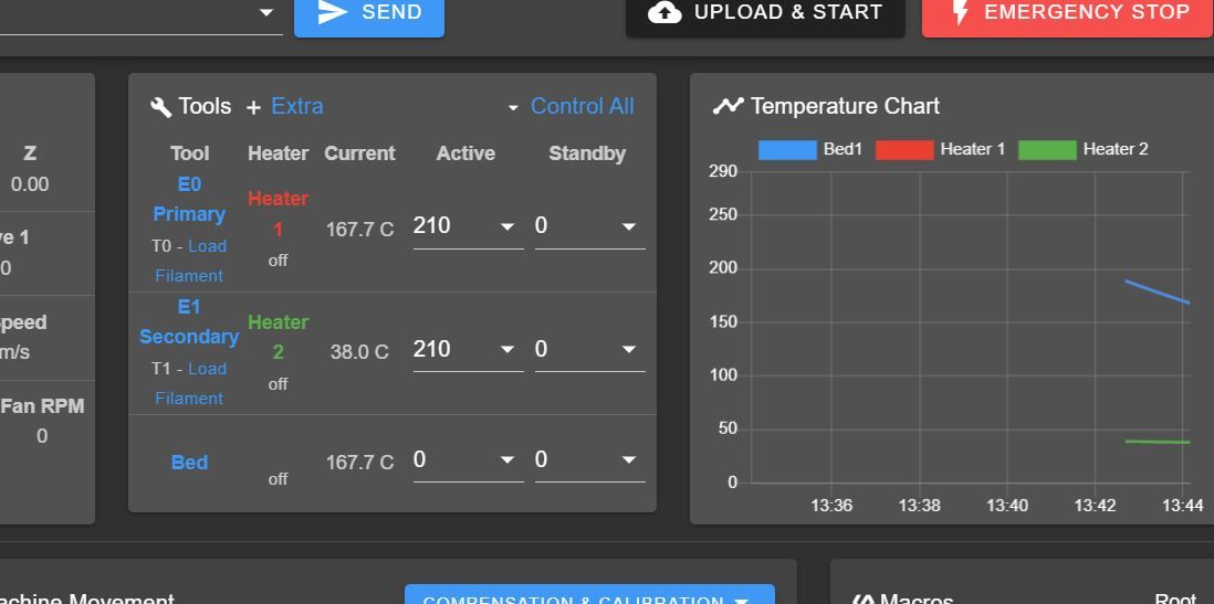
      The sensor readings are perfectly fine, until the Z-axis stepper motors start moving. The readings of the sensor go to 2000, indicating open/circuit/ fault reading.

      I've used fully shielded thermistor cable, and grounded the shield. The thermistor cables are as far away from the stepper motor wires as possible.

      I really tried everything regarding the hardware, but i'm running out of options....

      Could it be possible that there is something wrong in my firmware config file? Or in the firmware itself? Since I think it's suspicious that all 3 thermistors ( on the SPI daughterboards ) run into this error.

      M18 ( turn steppers of ) resolved the issue. However when turning the steppers on, the error occurs again immediately.

      Error: Temperature reading fault on heater 2: sensor short to other wiring
      

      Any one some advice/ideas on how to solve this?

      M122 output:

      m122
      === Diagnostics ===
      RepRapFirmware for Duet 2 WiFi/Ethernet version 3.3 (2021-06-15 21:44:54) running on Duet WiFi 1.02 or later + DueX5
      Board ID: 0JD0M-9P6B2-NJ4S4-6J9FL-3SN6J-KS2GK
      Used output buffers: 3 of 24 (24 max)
      === RTOS ===
      Static ram: 23876
      Dynamic ram: 77144 of which 0 recycled
      Never used RAM 13396, free system stack 128 words
      Tasks: NETWORK(ready,13.3%,226) HEAT(delaying,0.1%,314) Move(notifyWait,0.1%,305) DUEX(notifyWait,0.0%,24) MAIN(running,86.3%,441) IDLE(ready,0.1%,29), total 100.0%
      Owned mutexes: WiFi(NETWORK)
      === Platform ===
      Last reset 00:12:26 ago, cause: power up
      Last software reset time unknown, reason: User, GCodes spinning, available RAM 13604, slot 1
      Software reset code 0x0003 HFSR 0x00000000 CFSR 0x00000000 ICSR 0x0041f000 BFAR 0xe000ed38 SP 0x00000000 Task MAIN Freestk 0 n/a
      Error status: 0x0c
      Aux0 errors 0,1,0
      Step timer max interval 0
      MCU temperature: min 29.3, current 36.9, max 38.0
      Supply voltage: min 23.8, current 24.2, max 24.6, under voltage events: 0, over voltage events: 0, power good: yes
      Heap OK, handles allocated/used 0/0, heap memory allocated/used/recyclable 0/0/0, gc cycles 0
      Driver 0: position 5000, standstill, SG min/max 0/108
      Driver 1: position 95000, standstill, SG min/max not available
      Driver 2: position 12094, standstill, SG min/max not available
      Driver 3: position 0, standstill, SG min/max not available
      Driver 4: position 0, standstill, SG min/max not available
      Driver 5: position 0, standstill, SG min/max 0/111
      Driver 6: position 0, standstill, SG min/max 0/274
      Driver 7: position 0, standstill, SG min/max 0/275
      Driver 8: position 0, standstill, SG min/max 0/266
      Driver 9: position 0, standstill, SG min/max 0/297
      Driver 10: position 0
      Driver 11: position 0
      Date/time: 2022-02-09 13:46:14
      Cache data hit count 4294967295
      Slowest loop: 16.14ms; fastest: 0.17ms
      I2C nak errors 0, send timeouts 0, receive timeouts 0, finishTimeouts 0, resets 0
      === Storage ===
      Free file entries: 10
      SD card 0 detected, interface speed: 20.0MBytes/sec
      SD card longest read time 3.2ms, write time 0.0ms, max retries 0
      === Move ===
      DMs created 83, maxWait 35109ms, bed compensation in use: mesh, comp offset 0.000
      === MainDDARing ===
      Scheduled moves 14, completed moves 14, hiccups 0, stepErrors 0, LaErrors 0, Underruns [0, 0, 0], CDDA state -1
      === AuxDDARing ===
      Scheduled moves 0, completed moves 0, hiccups 0, stepErrors 0, LaErrors 0, Underruns [0, 0, 0], CDDA state -1
      === Heat ===
      Bed heaters = 2 3 4 -1, chamberHeaters = -1 -1 -1 -1
      === GCodes ===
      Segments left: 0
      Movement lock held by null
      HTTP is idle in state(s) 0
      Telnet is idle in state(s) 0
      File is idle in state(s) 0
      USB is idle in state(s) 0
      Aux is idle in state(s) 0
      Trigger is idle in state(s) 0
      Queue is idle in state(s) 0
      LCD is idle in state(s) 0
      Daemon is idle in state(s) 0
      Autopause is idle in state(s) 0
      Code queue is empty.
      === DueX ===
      Read count 1, 0.08 reads/min
      === Network ===
      Slowest loop: 15.64ms; fastest: 0.00ms
      Responder states: HTTP(0) HTTP(0) HTTP(0) HTTP(0) FTP(0) Telnet(0), 0 sessions
      HTTP sessions: 1 of 8
      - WiFi -
      Network state is active
      WiFi module is connected to access point 
      Failed messages: pending 0, notready 0, noresp 0
      WiFi firmware version 1.26
      WiFi MAC address f4:cf:a2:71:f6:e7
      WiFi Vcc 3.37, reset reason Power up
      WiFi flash size 2097152, free heap 24912
      WiFi IP address 192.168.1.245
      WiFi signal strength -69dBm, mode 802.11n, reconnections 0, sleep mode modem
      Clock register 00002002
      Socket states: 4 0 0 0 0 0 0 0
      

      Config.g :

      ;Generated by Modix - 1.4
      ;Modix Big-Meter, Duex Expansion, Dual Printhead, Testing
      ; Configuration file for Duet WiFi (firmware version 3.3)
      
      
      ; General preferences_________________________________________________________
      G90                                             			; send absolute coordinates...
      M83                                             			; ...but relative extruder moves
      M111 S0 								; Debug off
      M555 P2 								; Set output to look like Marlin
      M575 P1 B57600 S1							; Set auxiliary serial port baud rate and require checksum (for PanelDue)
      
      
      ; Network_____________________________________________________________________
      M550 P"Big Meter (RRF3.3)"                         			; set printer name
                    					; Set password (optional)
      M552 S1                                        				; enable network
      ;M552 P0.0.0.0								; Uncomment this command for using Duet Ethernet board
      M586 P0 S1                                      			; enable HTTP
      M586 P1 S0                                      			; disable FTP
      M586 P2 S0                                      			; disable Telnet
      
      ; Drives_________________________________________________________________________
      ;Main board______________________________________________________________________
      M569 P0 S0                                                     		; Physical drive 0 . X1
      M569 P1 S1                                                       	; Physical drive 1 . X2
      M569 P2 R-1                                                        	; Physical drive 2 . Canceled
      M569 P3 S1                                                       	; Physical drive 3 . Main Extruder
      M569 P4 S0                                                       	; Physical drive 4 . Secondary Extruder
      ;Duex5 board_____________________________________________________________________
      M569 P5 S0                                                       	; Physical drive 5 . Y
      M569 P6 S0                                                       	; Physical drive 6 . Z1 (0,1000) 
      M569 P7 S0                                                       	; Physical drive 7 . Z2 (0,0) 
      M569 P8 S0                                                       	; Physical drive 8 . Z3 (1000,0) 
      M569 P9 S0                                                       	; Physical drive 9 . Z4 (1000,1000) 
      
      ;Settings_________________________________________________________
      M584 X0:1 Y5 Z6:7:8:9 U1 E3:4 P3					; Driver mapping
      M671 X-181:-181:1049:1049 Y1066:-58:-58:1066 S10    			; Anticlockwise 
      ;___________________________________________________________________
      M350 X16 Y16 U16 I1  		                           		; Configure microstepping with interpolation
      M350 Z16 E16:16 I0              		                	; Configure microstepping without interpolation
      M92 X100.00 Y100.00 Z2000.00 E415.50:418.500 U100.00      	; Set steps per mm
      M566 X200 Y200 Z30.00 E120.00:120.00 U240 P1               	; Set maximum instantaneous speed changes (mm/min)
      M203 X9000.00 Y9000.00 Z200.00 E1200.00:1200.00 U9000.00    ; Set maximum speeds (mm/min)
      M201 X500 Y500 Z120.00 E250.00:250.00 U1000             	; Set accelerations (mm/s^2)
      M204 P300                                      				; Set print and travel accelerations  (mm/s^2)
      M906 X1800 Y1800.00 E1000.00:1000.00 U1800 I40 				; Set motor currents (mA) and motor idle factor in per cent
      M906 Z1800 I50											; Set motor currents (mA) and motor idle factor in per cent
      M84 S100                                          			; Set idle timeout - one minute
      
      ; Axis Limits
      M208 X0 Y0 Z-1 S1                               			; set axis minima
      M208 X1000 Y1000 Z1000 S0                          			; set axis maxima
      
      ; Endstops
      M574 X1 S1 P"xstop"                            				; configure switch-type (e.g. microswitch) endstop for low end on X via pin xstop
      M574 U1 S1 P"e0stop"                            			; configure switch-type (e.g. microswitch) endstop for low end on X via pin xstop
      M574 Y2 S1 P"ystop"                            				; configure switch-type (e.g. microswitch) endstop for low end on Y via pin ystop
      
      ; Z-Probe
      M558 P5 C"^zprobe.in" H5 F120 T6000 A1 R0.7  				; set Z probe type to bltouch and the dive height + speeds
      M950 S0 C"duex.pwm5"
      G31 P500 X-14 Y21 Z1.047                     				; set Z probe trigger value, offset and trigger height
      M556 S50 X0 Y0 Z0                               			; set orthogonal axis compensation parameters
      M557 X-14:974 Y21:1009 S66.5                 				; define mesh grid
      M376 H10			                						; Height (mm) over which to taper off the bed compensation
      
      ; Heaters___________________________________________________________
      ;M140 H-1    												; disable heated bed (overrides default heater mapping)
      ; bed heater0
      M308 S2 P"spi.cs1" Y"thermocouple-max31856" T"J"   ; configure sensor 0 as thermistor on pin bedtemp
      M950 H2 C"duex.e2heat" T2                              ; create bed heater output on exp.heater7 and map it to sensor 0
      M140 P0 H2                                              ; Define bed heater as heater 7 output
      M143 H2 S80                                          ; set temperature limit for heater 0 to 80C
      M570 H2 P420 T10 ; heater fault detection
      
      ; bed heater1
      M308 S3 P"spi.cs2" Y"thermocouple-max31856" T"J"   ; configure sensor 0 as thermistor on pin bedtemp
      M950 H3 C"duex.e3heat" T3                              ; create bed heater output on exp.heater7 and map it to sensor 0
      M140 P1 H3                                              ; Define bed heater as heater 7 output
      M143 H3 S80                                          ; set temperature limit for heater 0 to 80C
      M570 H3 P420 T10 ; heater fault detection
      
      ; bed heater2
      M308 S4 P"spi.cs3" Y"thermocouple-max31856" T"J"   ; configure sensor 0 as thermistor on pin bedtemp
      M950 H4 C"duex.e4heat" T4                              ; create bed heater output on exp.heater7 and map it to sensor 0
      M140 P2 H4                                              ; Define bed heater as heater 7 output
      M143 H4 S80                                          ; set temperature limit for heater 0 to 80C
      M570 H4 P420 T10 ; heater fault detection
      
      ;E0_________________________________________________________________
      M308 S0 P"e0temp" Y"thermistor" T100000 B4725   			; configure sensor 0 as thermistor on pin e0temp
      M950 H0 C"e0heat" T0                            			; create nozzle heater output on e0heat and map it to sensor 0
      ;M307 H0 B0 S1.00                               			; PID calibration
      M307 H0 B0 R1.933 C204.4:156.5 D5.51 S1.00
      M143 H0 S285                                    			; set temperature limit for heater 0 to 280C
      
      ;E1_________________________________________________________________
      M308 S1 P"e1temp" Y"thermistor" T100000 B4725   			; configure sensor 1 as thermistor on pin e1temp
      M950 H1 C"e1heat" T1                            			; create nozzle heater output on e1heat and map it to sensor 1
      ;M307 H1 B0 S1.00                               			; PID calibration
      M143 H1 S285                                    			; set temperature limit for heater 1 to 280C
                                         				
      ; Fans______________________________________________________________
      M950 F0 C"fan0" Q500                            			; create fan 0 on pin fan0 and set its frequency
      M106 P0 S0 H-1                                  			; set fan 0 value. Thermostatic control is turned on
      M950 F1 C"fan1" Q500                            			; create fan 1 on pin fan1 and set its frequency
      M106 P1 S0 H-1                                  			; set fan 1 value. Thermostatic control is turned on
      M950 F2 C"duex.fan7" Q500                            			; create LED on pin fan2 and set its frequency
      M106 P2 S0 H-1                               				; Disable fan channel for LED
      ;M106 P2 S255								; LED on by default
      M950 F3 C"duex.fan5" Q500                       			; create fan 3 on pin fan1 and set its frequency
      M106 P3 S255 H0 T45                             			; set fan 3 value. Thermostatic control is turned on
      M950 F4 C"duex.fan6" Q500                       			; create fan 4 on pin fan1 and set its frequency
      M106 P4 S255 H1 T45                             			; set fan 4 value. Thermostatic control is turned on
      
      
      ; Tools______________________________________________________________
      ;T0_________________________________________________________________
      M563 P0 S"E0 Primary" D0 H0 F0                  			; define tool 0
      G10 P0 X0 Y0 Z0                                 			; set tool 0 axis offsets
      G10 P0 R0 S210                                  			; set initial tool 0 active and standby temperatures to 0C
      
      ;T1_________________________________________________________________
      M563 P1 S"E1 Secondary" D1 H1 F1                			; define tool 1
      G10 P1 X0 Y49 Z0                                			; set tool 1 axis offsets
      G10 P1 R0 S210                                    			; set initial tool 1 active and standby temperatures to 0C
      
      
      ; Custom settings__________________________________________________
      
      M950 J0 C"exp.e2stop"  					  		; create Input Pin 0 on pin E2 to for M581 Command.
      M581 T1 P0 S0 R1							; Regular filament sensor for E0 As External Trigger
      ;M591 D0 P7 C"e1stop" S1 L4.2 E10 R10:300				; Clog Detector E0 [Add-On]
      
      M950 J1 C"exp.e3stop"  					  		; create Input Pin 1 on pin E3 to for M581 Command.
      M581 T1 P1 S0 R1							; Regular filament sensor for E1 As External Trigger
      ;M591 D1 P7 C"zstop" S1 L4.2 E10 R10:300				; Clog Detector E1 [Add-On]
      
      M950 J2 C"exp.e4stop"  					  		; create Input Pin 2 on pin E4 to for M581 Command.
      ;M581 T0 P2 S0 R0							; Crash Detector   [Add-On]
      
      
      M911 S21.0 R23.0 P"M913 X0 Y0 G91 M83 G1 Z1 E-5 F1000" ; auto save/restart on power loss
      
      posted in Duet Hardware and wiring
      Bart1992undefined
      Bart1992
    • RE: Configure multiple bed heaters

      @dc42

      Thank you for responding.
      Can you explain how I should let them show up in the DWC?
      Currently only bed1 is shown ( see attachment )!

      Onlybed1.jpg
      Onlybed1_2.jpg

      posted in Tuning and tweaking
      Bart1992undefined
      Bart1992
    • RE: Configure multiple bed heaters

      @phaedrux

      Unfortunately we are unable to upgrade to RRF3 yet.

      But I think it must be possible to configure RRF2 using multiple bed heaters to show up in the DWC and Paneldue?
      According to this post, is must be possible : https://forum.duet3d.com/topic/3516/using-multiple-bed-heaters/21

      posted in Tuning and tweaking
      Bart1992undefined
      Bart1992
    • RE: Configure multiple bed heaters

      @phaedrux Thanks for your response

      As requested :

      Duet firmware version : 2.05
      DWC version : 2.07

      M122 output :
      ( had to do it like this, otherwise it's marked as spam? )

      m122output.txt

      M98 P"config.g" output :

      M98 P"config.g"
      HTTP is enabled on port 80 FTP is disabled TELNET is disabled Warning: Heater 6 appears to be over-powered. If left on at full power, its temperature is predicted to reach 365C. Error: M106: Fan 2 is disabled Error: M106: Fan 3 is disabled Error: M106: Fan 4 is disabled Error: M106: Fan 7 is disabled Error: M106: Fan 8 is disabled
      
      posted in Tuning and tweaking
      Bart1992undefined
      Bart1992
    • Configure multiple bed heaters

      Hi,

      I'm trying to configure a multiple bed heaters setup, however i'm not succeeding in getting the bed heaters to show up in the DWC and Paneldue.

      My specific heater config looks like :

      ; Heaters___________________________________________________________
      
      ; Bed1 parameters 
      M140 P0 H0
      M305 P3 S"Bed1" X150 T"J"  ; Set thermocouple heater 0 = bed 1 thermocouple = J type 
      M143 H0 S125 ; Set temperature limit for heater 0 to 125C
      
      ; Bed2 parameters 
      M140 P3 H6
      M305 P3 S"Bed2" X151 T"J"  ; Set thermocouple heater 0 = bed 1 thermocouple = J type 
      M307 H6 B1 S1.00
      M143 H6 S125 ; Set temperature limit for heater 0 to 125C
      
      ; Bed3 parameters 
      M140 P4 H7
      M305 P3 S"Bed3" X152 T"J"  ; Set thermocouple heater 0 = bed 1 thermocouple = J type 
      M307 H6 B1 S1.00
      M143 H6 S125 ; Set temperature limit for heater 0 to 125C
      
      ;E0_________________________________________________________________
      M305 P1 T100000 B4725 C7.060000e-8 R4700                     	    ; Set thermistor + ADC parameters for heater 1
      M143 H1 S285                                                        ; Set temperature limit for heater 1 to 285C
      
      ;E1_________________________________________________________________
      M305 P2 T100000 B4725 C7.060000e-8 R4700                       	    ; Set thermistor + ADC parameters for heater 2
      M143 H2 S285                                                        ; Set temperature limit for heater 2 to 285C


      and for completion, the complete config looks like :

       
      ; General preferences_______________________________________________
      G90                                          				; Send absolute coordinates...
      M83                                         				; ...but relative extruder moves
      M111 S0 													; Debug off
      M555 P2 													; Set output to look like Marlin
      M575 P1 B57600 S1											; Set auxiliary serial port baud rate and require checksum (for PanelDu
      
      ; Network________________________________________________________ֹֹֹֹֹ___
      M550 P"Big Meter - Kverneland Group"                          							; Set machine name
      ;M551 P"MODIX3D"               										; Set password (optional)
      M552 S1                                 							; Enable network
      ;M552 P0.0.0.0														; Uncomment this command for using Duet Ethernet board
      M586 P0 S1                                							; Enable HTTP
      M586 P1 S0                               					    	; Disable FTP
      M586 P2 S0                                							; Disable Telnet
      
      ; Drives
      ;Main board______________________________________________________________________
      M569 P0 S0                                                     		; Physical drive 0 . X1
      M569 P1 S1                                                       	; Physical drive 1 . X2
      M569 P2 R-1                                                        	; Physical drive 2 . Canceled
      M569 P3 S1                                                       	; Physical drive 3 . Main Extruder
      M569 P4 S0                                                       	; Physical drive 4 . Secondery Extruder
      ;Duex5 board_____________________________________________________________________
      M569 P5 S0                                                       	; Physical drive 5 . Y
      M569 P6 S0                                                       	; Physical drive 6 . Z1 (0,1000) 
      M569 P7 S0                                                       	; Physical drive 7 . Z2 (0,0) 
      M569 P8 S0                                                       	; Physical drive 8 . Z3 (1000,0) 
      M569 P9 S0                                                       	; Physical drive 9 . Z4 (1000,1000) 
      ;___________________________________________________________________ 
      M584 X0:1 Y5 Z6:7:8:9 U1 E3:4 P3									; Driver mapping
      M671 X-181:-181:1049:1049 Y1066:-58:-58:1066 S10    			  	; Anticlockwise 
      ;___________________________________________________________________
      M350 X16 Y16 Z16 E16:16 U16 I1                                		; Configure microstepping with interpolation
      M92 X100.00 Y100.00 Z2000.00 E440.530:418.500 U100.00      			; Set steps per mm
      M566 X240 Y360 Z30.00 E120.00:120.00 U240 P1                    	; Set maximum instantaneous speed changes (mm/min)
      M203 X9000.00 Y9000.00 Z200.00 E1200.00:1200.00 U9000.00    		; Set maximum speeds (mm/min)
      M201 X1000 Y1000 Z120.00 E250.00:250.00 U1000             			; Set accelerations (mm/s^2)
      M204 P500                                      						; Set print and travel accelerations  (mm/s^2)
      M906 X1800 Y1800.00 E1000.00:1000.00 U1800 I40 						; Set motor currents (mA) and motor idle factor in per cent
      M906 Z1800.00 I50 													; Set motor currents (mA) and motor idle factor in per cent
      M84 S60 X Y U E0 E1                                                 ; Set idle timeout - one minute
      
      ; Axis Limits_______________________________________________________
      M208 X0:1000 Y0:1000 Z0:1000 U0:1000		                        ; Set axis minima and maxima
      
      ; Endstops__________________________________________________________
      M574 X1 Y2 U1 S1                                            		; Set active low and disabled endstops
      	
      ; Z-Probe___________________________________________________________
      M574 Z2 S2                                                     		; Set endstops controlled by probe
      M307 H7 A-1 C-1 D-1                                     			; Disable heater on PWM channel for BLTouch
      M558 P9 H5 F120 T9000 A1 R0.7            			       			; Set Z probe type to bltouch and the dive height + speeds
      G31 P500 X-14 Y21 Z1.284  	                    		     		; Set Z probe trigger value, offset and trigger height(Z-Offset)
      M557 X-14:974 Y21:1009 S52 		                        			; Define mesh grid. 400 Points
      M376 H30			                    							; Height (mm) over which to taper off the bed compensation
      
      ; Heaters___________________________________________________________
      ;M140 H-1                                                            ; Disable heated bed
      ;M307 H0 A-1 C-1 D-1												 ; Disable heater on PWM channel
      
      ; Bed1 parameters 
      M140 P0 H0
      M305 P3 S"Bed1" X150 T"J"  ; Set thermocouple heater 0 = bed 1 thermocouple = J type 
      M143 H0 S125 ; Set temperature limit for heater 0 to 125C
      
      ; Bed2 parameters 
      M140 P3 H6
      M305 P3 S"Bed2" X151 T"J"  ; Set thermocouple heater 0 = bed 1 thermocouple = J type 
      M307 H6 B1 S1.00
      M143 H6 S125 ; Set temperature limit for heater 0 to 125C
      
      ; Bed3 parameters 
      M140 P4 H7
      M305 P4 S"Bed3" X152 T"J"  ; Set thermocouple heater 0 = bed 1 thermocouple = J type 
      M307 H6 B1 S1.00
      M143 H6 S125 ; Set temperature limit for heater 0 to 125C
      
      ;E0_________________________________________________________________
      M305 P1 T100000 B4725 C7.060000e-8 R4700                     	    ; Set thermistor + ADC parameters for heater 1
      M143 H1 S285                                                        ; Set temperature limit for heater 1 to 285C
      ;M307 H1 A# C# D# V# S1.0 B0                            			; PID calibration 
      ;E1_________________________________________________________________
      M305 P2 T100000 B4725 C7.060000e-8 R4700                       	    ; Set thermistor + ADC parameters for heater 2
      M143 H2 S285                                                        ; Set temperature limit for heater 2 to 285C
      ;M307 H2 A# C# D# V# S1.0 B0                             	   		; PID calibration


      ; Fans______________________________________________________________
      M106 P0 S0 I0 F500 H-1 C"E0 BlowerFan"                       	    ; Set fan 0 value, PWM signal inversion and frequency. Thermostatic control is turned off
      M106 P1 S0 I0 F500 H-1 C"E1 BlowerFan"                              ; Set fan 1 value, PWM signal inversion and frequency. Thermostatic control is turned off
      M106 P5 T46 H1 							    						; Set fan 5. Thermostatic control is turned on
      M106 P6 T46 H2 							   							; Set fan 6. Thermostatic control is turned on
      M106 P2 I-1                                                         ; LED (optional)
      M106 P3 I-1                                                         ; LED (optional)
      M106 P4 I-1                                                         ; LED (optional)
      M106 P7 I-1                                                         ; Main LED 
      M106 P8 I-1                                                         ; LED (optional)
      
      ; Tools
      ;T0_________________________________________________________________
      M563 P0 S"E0 Primary" D0 H1 F0                      				; Define tool 0
      G10 P0 X0 Y0 Z0                                   					; Set tool 0 axis offsets
      G10 P0 R0 S210                                		  				; Set initial tool 0 active and standby temperatures to 0C
      ;T1_________________________________________________________________
      M563 P1 S"E1 Secondary" D1 H2 F1                     			    ; Define tool 1
      G10 P1 X0 Y49 Z0                             			    		 ; Set tool 1 axis offsets
      G10 P1 R0 S210                               		     	 		; Set initial tool 1 active and standby temperatures to 0C
      
      ; Automatic power saving____________________________________________
      M911 S22.5 R29.0 P"M913 X0 Y0 G91 M83 G1 Z3 E-5 F1000"              ; Set voltage thresholds and actions to run on power loss. Power Failure Pause
      	
      ; Custom settings___________________________________________________
      M591 D0:1 P1 C4 S1		   			       	    					; Regular filament sensor for E0 and E1
      ;M564 H0 S0                                                	    	; Negative movements are allowed
      

      Bed heater 2 and 3 don't appear in the DWC and Paneldue( bed heater H0 does ).

      Looking at the diagnostics ( M122 ), the heaters seem to be correctly defined

      === Bed heaters = 0 -1 6 7

      What am i doing wrong? Why are they not displayed? Giving them a name ( as noted in the docs M305 S parameter ) does not seem to help unfortunately.

      posted in Tuning and tweaking
      Bart1992undefined
      Bart1992