Duet3D Logo Duet3D
    • Tags
    • Documentation
    • Order
    • Register
    • Login
    1. Home
    2. bruceg
    • Profile
    • Following 0
    • Followers 0
    • Topics 3
    • Posts 9
    • Best 0
    • Controversial 0
    • Groups 0

    bruceg

    @bruceg

    0
    Reputation
    1
    Profile views
    9
    Posts
    0
    Followers
    0
    Following
    Joined Last Online

    bruceg Unfollow Follow

    Latest posts made by bruceg

    • RE: 3.3 Heater Fault: M307 & Error Expected Value Mismatch?

      It turns out that there is a down spike or up spike in the hotend temperature signal on my machine that appears to coincide with the hotend heater turning on and off respectively. Presumably these spikes are, quite understandably, interfering with the auto tuning algorithm and are causing it to produce parameters which result in "temperature rising much more slowly than the expected" heater fault errors.

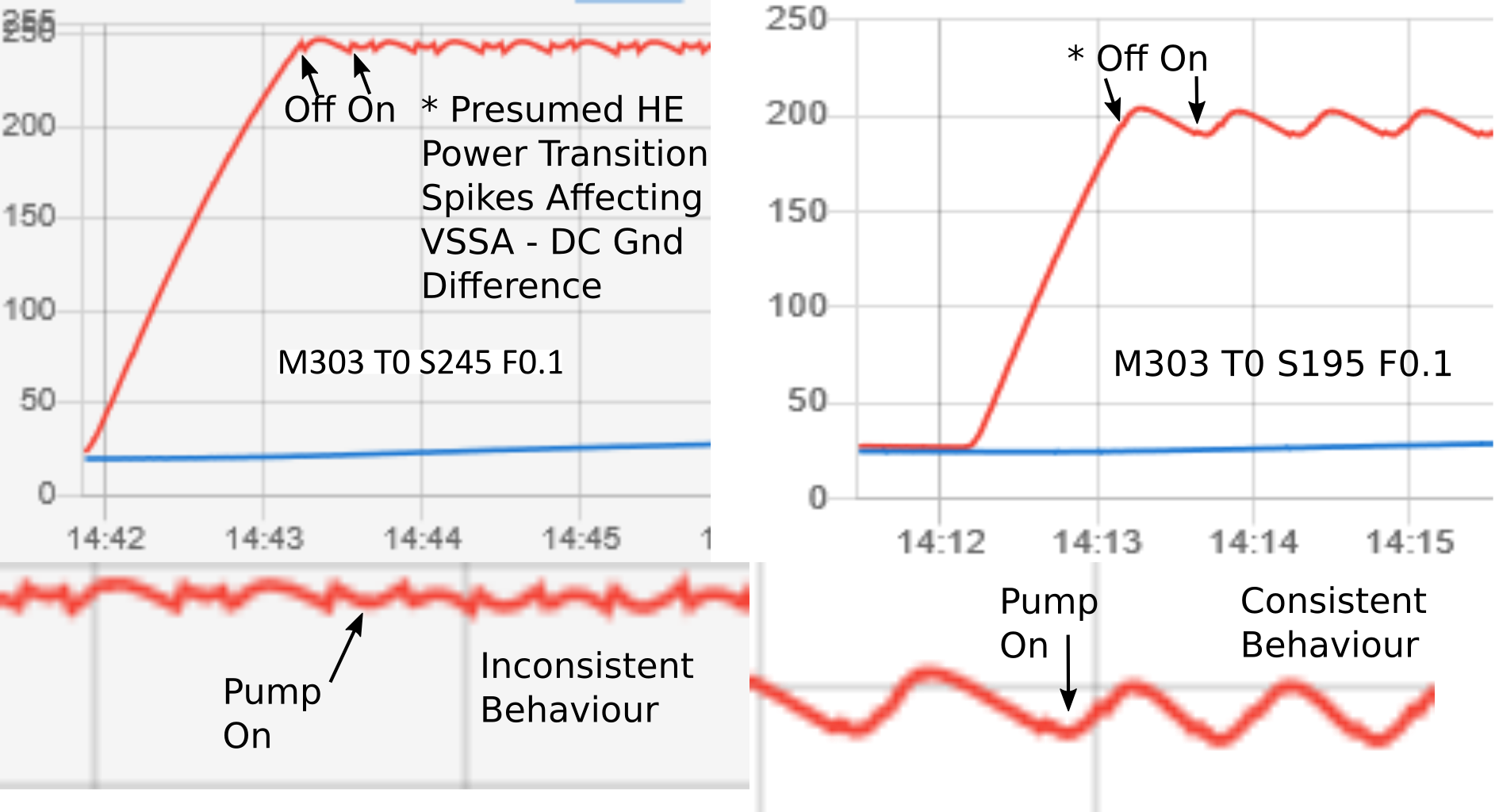
      My first thought is that, due to my convoluted 12/24 VDC power system - v2max_duet_upgrade_dual_power_accelerometer_v1.0.pdf, there is some sort of VSSA-DC ground mismatch occurring when the heater goes from on to off during the auto tuning cycle. The effect is greater at higher temperatures - see below. My thinking is that, as thermister resistance is lower at higher temperatures producing a lower voltage at the Duet input pin, any change in VSSA-DC ground levels would have a relatively larger impact at higher temperature.

      To my mind, the drop in temperature occurring when the hotend heater turns off suggests a lowering of the DC ground ground level relative to VSSA producing a higher voltage at the Duet input and visa versa when the hotend heater turns on.

      The image below shows the difference in the temperature signal spikes at 245 vs 195C and the zoomed in lower panels show the point in the auto tuning process when the pump is turned on as well as the behavior reported by the tuning algorithm. Looking at the 245C temperature signal it is amazing that the algorithm comes up with anything at all!
      Spike Magnitude 245 vs 195.png

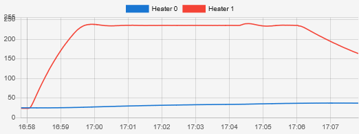
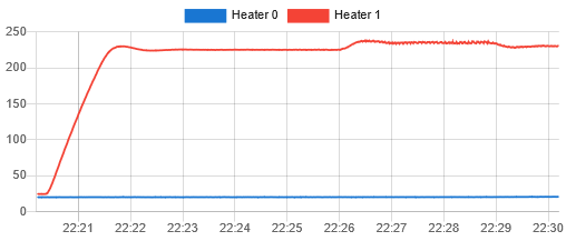
      For the moment, in order to have good response to cooling pump transitions etc, i will need to hand tune a set of parameters for every 5C or so due to the increased spiking effect at higher temperatures causing instability. Temperature chart below shows response for 225C "optimized" tuning at initially 225, then 235 and finally 230C.
      Test Image 27.png

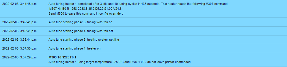
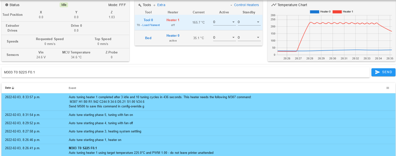
      The approach i took to get past the expected rise rate error was to (somewhat counterintuitively to my dim mind) lower the R and/or C values until the error resolved, get the hotend up to temperature, then increase R until the "spikiness" in the temperature response at steady state resolved followed by adjustment of the dead time to remove the slow oscillation but retain responsiveness to cooling changes. For most temperatures, a fairly significant reduction of the auto tuning generated C parameters was required in order to avoid the expected rise error heater fault after the manual adjustments.

      On the off chance it may be of some to use to someone running into a similar situation with a less than ideal hotend temperature signal causing the auto tuning algorithm to generate expected rise rate error heater faults, some data from my testing and resolution process is included below.
      Tuning Table.png
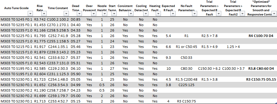
      It is interesting to note the effect of nozzle height above the bed (last 4 lines of the table above) and cooling pump speed on the cooling off:on C parameters. Based on some flow visualization studies i did with the pump duct, i suspect the paradoxical reduction in C parameter differences at full pump speed may be due to a bigger proportion of each air jet stream escaping under the lower surface of the duct at higher velocities and consequently reducing impingment on the nozzle.

      I will try another hotend with the same heater/thermister setup shortly to see if the problem follows and at some point in the next few months will finally convert the machine to straight 24V.

      posted in Tuning and tweaking
      brucegundefined
      bruceg
    • RE: 3.3 Heater Fault: M307 & Error Expected Value Mismatch?

      @phaedrux

      Well, having some good entertainment with the auto tuning. Need to do a few more trials and collate some hopefully coherent findings. In the mean time did some manual tuning of the R and D values. R = 5 combined with D = 4 in conjunction with the model produced from M307 H1 S245 F0.1 (behavior was intriguing) do not invoke a heater fault of the temperature rising much more slowly than the expected variety, and produce a reasonably stable temperature at 235, albeit with a response that is a little on the sluggish side.

      Think at the moment pump interference can be ruled out unless there is a diabolical feedback through the ground affecting heater voltage in a way which interacts with highly responsive tuning parameters.

      Attached image shows response to temperature set point of 235 from ambient of ~25 and pump running at 20%. Nozzle is 1 mm above bed (directly over the bed thermistor hence slow rise of bed temp despite bed heater being off). Pump is turned off at ~ 17:34:20
      Test Image 2.png

      posted in Tuning and tweaking
      brucegundefined
      bruceg
    • RE: 3.3 Heater Fault: M307 & Error Expected Value Mismatch?

      @phaedrux
      Certainly possible but i don't think so as i have had the air pump for several years and have not noticed an effect in the past. The pump is driven through optoisolators and external mosfets - but could always have something coming back on the common 24VDC ground i suppose (a circuit diagram is linked in an earlier post of mine which is linked the first post of this topic in the section explaining the 12/24V setup).

      Just playing with tuning parameters now, increasing dead time is helping. Once something workable is reached will do a trial with the pump on and off.

      posted in Tuning and tweaking
      brucegundefined
      bruceg
    • RE: 3.3 Heater Fault: M307 & Error Expected Value Mismatch?

      @phaedrux

      Sorry, forgot to include the M303 parameters used (yes was tuned as tool), here they are
      M303 Paramters.png

      Well i have certainly have had some fun with intermittent hotend wiring connections in the past, i think the current noise at higher temperatures is associated with the tuning parameters as the temperatures are relatively steady at lower temperatures and when heater is off as well as during the tuning cycles. Also temperature indication was stable at printing temperatures just prior to the update to 3.3.

      Will try your suggestion of tuning to a higher temperature (will use 245 as the hotends are fully lined with PTFE).

      Given that wiring problems always need to be considered, will also tweak the tuning parameters to see noise improves or not. If not will go hunting.

      Thanks,
      Bruce

      posted in Tuning and tweaking
      brucegundefined
      bruceg
    • 3.3 Heater Fault: M307 & Error Expected Value Mismatch?

      Problem: After updating to 3.3 have been experiencing consistent heater 1 fault: temperature rising much more slowly than the expected xxC/s. Reported expected values in heater fault messages are in the range of 5.9 to 6.8C vs an M307 R value (determined by 3.3 auto tuning) of ~ 1.96.

      While this problem is easily worked around by setting the M307 R value to around 0.5 or so, i have a few questions:

      1. Should the expected rise rate value that triggers the heater fault be ~75 % of the M307 R value? (thought i read that somewhere in the documentation)

      2. Is the expected rise rate fixed or does it vary based on the hotend temperature at the time of the request for increased temperature?

      3. Is the M307 R value solely used for heater fault purposes or is it also a parameter of the heater temperature control algorithm?

      4. Do i have an error or omission in my config.g that is preventing the tuned R value from being applied to the T0 heater?

      5. Is it likely that there is something about my hotend setup that is less than suitable for the current auto tuning algorithm?

      6. Other avenues that i should consider for trouble shooting?

      Thank you,
      Bruce

      Firmware 3.3
      DWC 3.3
      Hardware Duet2(Ethernet) PCB 1.04b
      Printer has one hotend (T0/H1) with an ~40W heating element. Part cooling is via an air pump and nozzle surrounding duct (which is quite efficient - 10% is a lot of cooling).
      Duct.png
      Hotend and bed are powered by 12V and Duet2 is powered from 24V.
      Hotend has SeeMeCNC accelerometer board (not used for leveling) which uses a common ground for all components including thermister.
      Bed heater functions well with 3.3 auto tuned values.

      Problem appeared after update from 2.05.1 to 3.3 (with an intermediary update to 3.0). Prior to update hotend and auto tuning +/- some minor tweaks have functioned well. Indicated hotend temperatures usually fluctuated ~ +/- 0.2 C or less during reasonably steady state printing conditions.

      Heater and Fan section of config.g below, complete config.g here config.g.

      ; Heaters
      M308 S0 P"bedtemp" Y"thermistor" T100000 B4138 ; configure sensor 0 as thermistor on pin bedtemp
      M950 H0 C"bedheat" T0                          ; create bed heater output on bedheat and map it to sensor 0
      M307 H0 B0 S1.00                               ; disable bang-bang mode for the bed heater and set PWM limit
      M140 H0                                        ; map heated bed to heater 0
      M143 H0 S120                                   ; set temperature limit for heater 0 to 120C
      
      M308 S1 P"e0temp" Y"thermistor" T100000 B4138  ; configure sensor 1 as thermistor on pin e0temp
      M950 H1 C"e0heat" T1                           ; create nozzle heater output on e0heat and map it to sensor 1
      M307 H1 B0 S1.00                               ; disable bang-bang mode for heater  and set PWM limit
      M143 H1 S280                                   ; set temperature limit for heater 1 to 280C
      
      M308 S2 Y"drivers" A"DRIVERS"   	       ; configure sensor 2 as temperature warning and overheat flags on the TMC2660 on Duet
      M308 S4 Y"mcu-temp" A"MCU"   		       ; configure sensor 3 as thermistor on pin e1temp for left stepper
      
      ; Fans
      M950 F0 C"fan0" Q20000                         ; create fan 0 on pin fan0 and set its frequency
      M106 P0 S0 H-1                                 ; set fan 0 value. Thermostatic control is turned off
      M950 F1 C"fan1" Q500                           ; create fan 1 on pin fan1 and set its frequency
      M106 P1 S1 H1 T55                              ; set fan 1 value. Thermostatic control is turned on ###No effect until accelerometer board replaced###
      
      M950 F2 C"fan2" Q100                	       ; create fan 2 on pin fan2 and set its frequency
      M106 P2 H2:4 L0.25 X0.05 B0.25 T35:60           ; set fan 2 value, turn on at 5% if the CPU temperature reaches 35C, and increase to full speed gradually as the temperature rises to 60C
      
      ; Tools
      M563 P0 D0 H1 F0                               ; define tool 0
      G10 P0 X0 Y0 Z0                                ; set tool 0 axis offsets
      G10 P0 R0 S0                                   ; set initial tool 0 active and standby temperatures to 0C
      

      Autotuning results with nozzle ~ 1 mm above bed and bed heater off
      Tuning F0.1 Bed Off H1.03 Result.png
      Autotuning results with nozzle ~ 1 mm above bed and bed heater on at 75C
      Tuning F0.1 Bed 75 H1.03 Result Unstable.png

      Temperature Chart and upper portion of console (6:23 p.m. and later) show hot end response with M307 R value set to 0.5. Air pump running at 10%. Temperature initially set to 140C then 235C then 225C. M307 R value changed to 1.958 at 6:30 p.m.. Air pump turned off at ~6:32:30 p.m..
      Lower portion of console (6:21 p.m. and earlier) shows variation in heater fault expected rise rate. Starting temperature ~ 50C in each instance.
      Change R to 0.5 then Back Fan 10 until last block then off - Variation in Expected R.png

      posted in Tuning and tweaking
      brucegundefined
      bruceg
    • RE: Unable to Connect Duet Ethernet via Web Interface

      Thank you, that was the required step. My apologies, i know i came across it whilst perusing the documentation earlier.

      posted in General Discussion
      brucegundefined
      bruceg
    • Unable to Connect Duet Ethernet via Web Interface

      Duet Ethernet v1.02, Firmware 1.19, initial setup out of the box, powered via usb. Web browser is Firefox 60.0.1 (32-bit)

      When attempting to check access to Duet Web interface get server not found / problem loading page error for duettest.local / IP address respectively.

      Able to connect via YAT. Initial power up was made without ethernet connection. When ethernet cable is connected yellow led on Duet ethernet board is on solid (red diagnostic led on main board is off), green ethernet led flashes intermittently.

      Have tried connecting through Netgear GS308 ethernet switch and directly from PC (Liva X Mini PC Win10). PC successfully connects to network via ethernet port.

      Below is terminal session showing IP address and network running status. When i first connected via usb without the ethernet port connected i did not see the errors associated with running config.g This is my first crack at the Duet so any ideas about how to proceed with troubleshooting will be much appreciated.

      Thank you,
      Bruce

      RepRapFirmware for Duet Ethernet Version 1.19 dated 2017-08-14

      Executing config.g...Error: G-Code buffer '$s' length overflow
      Error: G-Code buffer '$s' length overflow
      Error: G-Code buffer '$s' length overflow
      M570 S parameter is no longer required or supported
      Warning: Heater 0 appears to be over-powered. If left on
      M552
      Network is enabled, configured IP address: 192.168.1.14, actual IP address: 192.168.1.14
      ok
      M552 S1
      ok
      M552 S0
      Network stopped
      ok
      M552 S1
      ok
      Network running, IP address = 192.168.1.14

      posted in General Discussion
      brucegundefined
      bruceg
    • RE: Dual Power (24V Duet VIN/12V Heaters) Circuit Sanity Check

      Very good, thank you. Replacing those accelerometer boards with a simple connector board is indeed the next item on the upgrade list.

      posted in Duet Hardware and wiring
      brucegundefined
      bruceg
    • Dual Power (24V Duet VIN/12V Heaters) Circuit Sanity Check

      Hello, first post on forum, just starting the Duet3D adventure.

      I am upgrading a SeeMeCNC RostockV2 which i had been running on dual voltage with the RAMBo (24V for the stepper motors and 12V for the heaters and fans etc). I would like to keep 24V for the steppers as i am using a Zesty Nimble extruder which has a 30:1 reduction ratio and benefits for the speed afforded by 24V. Also, i have just installed 0.9deg motors on the axis.

      The bed is a 12VDC heater and i have a small fleet of customized hot end/effectors which incorporate the SeeMeCNC accelerometer board which is constrained to 12V. Although the accelerometer probe output will not be utilized, the accelerometer board is integral to the hot ends and i would prefer to not modify them at this time.

      The Duet board is a V1.02 Duet Ethernet and i have a few questions regarding power and connection circuitry (please see attached schematic). 0_1527427927501_V2Max_Duet_Upgrade_Dual_Power_Accelerometer_V1.0.pdf

      1. 24V feed into 12V Circuit: Given that there is potential (i think) to feed 24V back into the 12V power supply through the Bed and E0 indicating LEDs (D6 & 7) when the mosfets (TR2 & 4) are not conducting, should a blocking diode (D11 & 10 on the "Power Management Board") be inserted before the BED- and E0- inputs to the Duet? Or can one rely on the indicating LED 4K7 limiting resistors (R65 & 67) to limit current into the 12V circuitry to about 2.5mA which "shouldn't cause any problems"....

      2. Hot End Thermister Connection: The accelerometer board forces a common ground for the hot end cooling fan (always on), hot end leds and thermistor. Between the fan and LEDs, the ground return current approaches 200mA. Is the correct approach to avoid bringing this current (and potential HE associated noise) back through VSSA by terminating the hot end common ground to the ground bus on the power management board?

      3. JohnSL FSR Board Connection: It was suggested on the SeeMeCNC forum that probe signal be brought in through the Z Probe input. Are there any specific considerations for taking this approach? I am hoping to use the E0 and E1 Stop inputs for user inputs in the future (an "E Stop" of sorts and an "Easy Quit Printing" button for my better half who often takes on late night print monitoring duties).

      Any comments appreciated.

      Thank you,
      Bruce

      posted in Duet Hardware and wiring
      brucegundefined
      bruceg