Duet3D Logo Duet3D
    • Tags
    • Documentation
    • Order
    • Register
    • Login
    1. Home
    2. bug2k22
    3. Best
    • Profile
    • Following 0
    • Followers 0
    • Topics 22
    • Posts 67
    • Best 9
    • Controversial 0
    • Groups 0

    Best posts made by bug2k22

    • Folgertech FT5 Duet Upgrade

      Picked up an old Folgertech FT5 a while ago. Finally got round to finishing the upgrade. Has many of the 713maker cnc upgraded mounts and brackets. Swapped out the old controller which was running Marlin with a Duet 6HC, Roto Toolboard, Microswiss NG extruder with a revo nozzle and a Dyze Design Horizon Z probe.

      It's not a fast printer but print quality seems good, probably needs a little tuning to get the best out of it.

      FT5-1_small.jpg

      FT5-2_small.jpg

      FT5-3_small.jpg

      FT5-4_small.jpg

      FT5-5_small.jpg

      posted in My Duet controlled machine
      bug2k22undefined
      bug2k22
    • RE: Mesh bed compensation, poor first layer?

      Just a brief follow up to this, I never could get a good first layer with this setup. I tried with a bltouch, inductive and IR sensors all gave similar results, the first layer was very inconsistent.
      I have now installed a dyze designs horizon z probe which uses the nozzle for z probing, mesh bed compensation now works as expected and I get very good, consistent first layers.

      posted in Tuning and tweaking
      bug2k22undefined
      bug2k22
    • RE: Anycubic Kobra 2 Max upgrade

      Just a brief update on this conversion. I could never get a good consistent first layer, the mesh bed levelling just did not seem to work as expected. Other threads discussed this but it's possibly down to the z probe offset from the nozzle and less than perfectly square construction. After spending far more time than I would have liked trying to work around this, I decided to swap the print head and z-probe out.
      I already have a printer using one of the dyze designs horizon z probes and this had solved bed mesh levelling issues on that printer so went with one of those along with an e3d revo roto extruder/revo hot end with a high flow hardened nozzle. Having the nozzle act as the z probe get around any issues with an offset z probe.
      I modelled up a new mount to fix to the x axis gantry and had this cut out of aluminium along with an adapter to attach the extruder to the horizon probe.
      This solution has solved the mesh levelling and now the first layer is consistent. The total weight of the new print head is within 10g the same as the original.

      new_mount_1.jpg

      new_mount_2.jpg

      new_mount_3.jpg

      posted in My Duet controlled machine
      bug2k22undefined
      bug2k22
    • RE: TRONXY VEHO 100 2E

      @kmjr20 I have a printer with 2 independent z motors and a bl touch as the z probe/endstop here is my homez.g which probes at the middle of the bed first, then levels the bed by checking each side of the bed where the z leadscrews are and then finally does another z height check in the middle of the bed once the left and right z motors have levelled.

      M561       ; Cancel any currently active mesh compensation
      ; increase Z
      G91                                    ; relative positioning
      G1 H2 Z5                               ; move Z relative to current position to avoid dragging nozzle over the bed
      G90                                    ; absolute positioning
      
      ; home Z
      ; NOTE: The following XY position is determined from the probe grid defined in the next section
      var xCenter = move.compensation.probeGrid.mins[0] + (move.compensation.probeGrid.maxs[0] - move.compensation.probeGrid.mins[0]) / 2 - sensors.probes[0].offsets[0]
      var yCenter = move.compensation.probeGrid.mins[1] + (move.compensation.probeGrid.maxs[1] - move.compensation.probeGrid.mins[1]) / 2 - sensors.probes[0].offsets[1]
      G1 X{var.xCenter} Y{var.yCenter} F6000 ; go to bed centre
      G30                                    ; probe the bed
      
      while true
          G30 P0 X0 Y150 Z-99999 ; probe near a leadscrew, half way along Y axis
          G30 P1 X252 Y150 Z-99999 S2 ; probe near a leadscrew and calibrate 2 motors
          if abs(move.calibration.initial.deviation) < 0.01 || iterations > 4
              break
      
      ; Probe the height again after syncing the z motors
      G1 X{var.xCenter} Y{var.yCenter} F6000 ; go to bed centre
      G30                                    ; probe the bed
      
      posted in Duet Hardware and wiring
      bug2k22undefined
      bug2k22
    • RE: Duet3 6HC SBC mode can't access after upgrade to 3.5

      @jay_s_uk Thanks, that's just what was needed. I had got caught up in the weeds of the wiki and never read the release notes for that release. I already had apparmor installed and configured, must have missed the 'apt install duetpimanagementplugin' bit.
      This all looks to be working perfectly now, many thanks.

      posted in Firmware installation
      bug2k22undefined
      bug2k22
    • Anycubic Kobra 2 Max upgrade

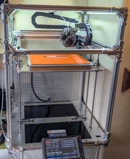
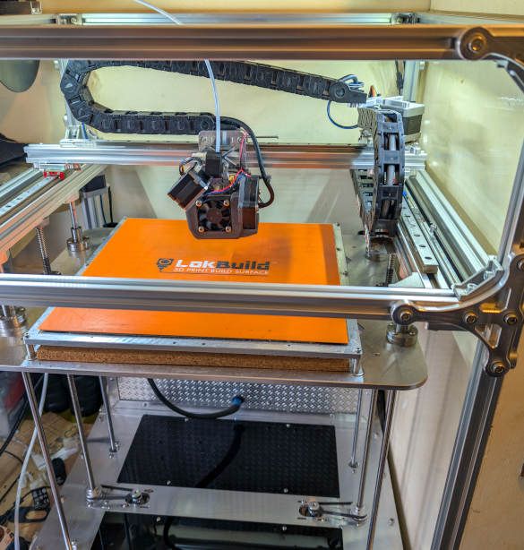
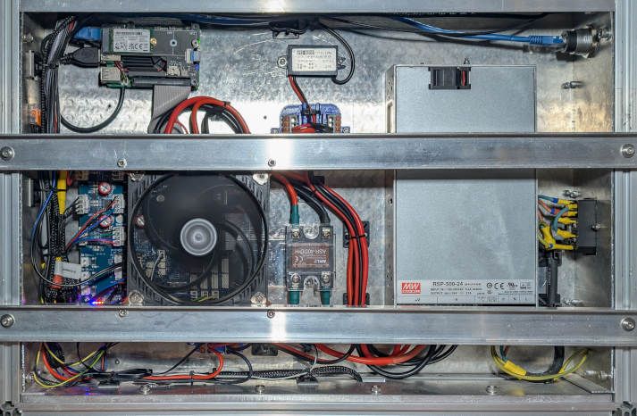
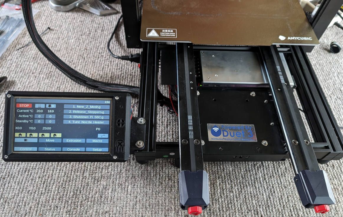
      I have had many little issues and things that annoyed me when using the Kobra 2 Max, with Anycubic running a proprietry closed version of Klipper removed a lot of the options for customizing the printer configuration. I decided to just remove the controller board and replace it with a Duet 3 6HC and 7" paneldue display. I did not want to use cloud accounts, phone apps or usb flash drives to transfers files to the printer. The printer did not have a local web gui.

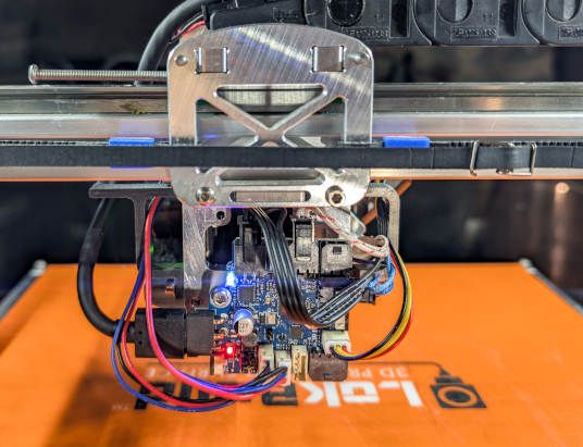
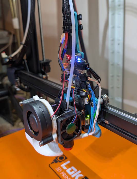
      The only thing that I could not get to work was the acceleromter on the print bed, the LIS2DW12 is supported but there is no connection to the interrupt pin on the chip, apparently klipper does not require this but the duet boards do. I replaced this with a Duet3D accelerometer. The same chip is used on the print head but there is a pad that is connected to the interrupt pin and can be used.

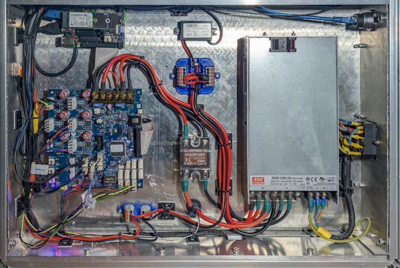
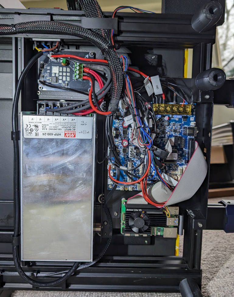
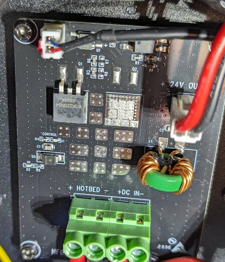
      The psu has a 500w rating, but I measured the usage at 460w just heating up the print bed without any steppers or the extruder running, a max draw over 570w while printing. I changed the psu for a Mean Well 648w supply to give it a bit more headroom and hopefully reliability.
      There is a separate pcb to power the heated bed and I ran the bed heater output from the 6hc to this board to power the bed heater.

      Kobra2Max_duet3__2.jpg

      Kobra2Max_duet3_1.jpg

      Kobra2Max_Heatbed_Power.jpg

      I've used conservative speeds/accelerations as the advertised rates are a little optimistic. This config works but could still use some tuning.
      config.g

      M550 P"Kobra 2 Max"      ; set persistent hostname
      
      M575 P1 S0 B57600         ; configure PanelDue support
      
      M569 P0.0 S1 D2             ; driver 0.0 goes forwards (Z axis)
      M569 P0.1 S1 D2             ; driver 0.1 goes forwards (Z axis)
      M569 P0.2 S1 D2             ; driver 0.2 goes forwards (extruder 0)
      M569 P0.4 S1 D2             ; driver 0.4 goes forwards (X axis)
      M569 P0.5 S0 D2             ; driver 0.5 goes backwards (Y axis)
      
      M906 X1960 Y2660 Z1400 E960 ; set motor driver currents
      
      M906 I60 ; set motor current idle factor
      M84 S30  ; set motor current idle timeout
      
      M669 K0 ; configure Cartesian kinematics
      
      M584 X0.4 Y0.5 Z0.0:0.1   ; set axis mapping
      M350 X16 Y16 Z16 I1       ; configure microstepping with interpolation
      M92 X80.3 Y80.3 Z401.5          ; configure steps per mm
      M208 X-5:430 Y-5:430 Z-0.4:500 ; set minimum and maximum axis limits
      M566 X600 Y600 Z12        ; set maximum instantaneous speed changes (mm/min)
      M203 X30000 Y25000 Z960   ; set maximum speeds (mm/min)
      M201 X2000 Y1000 Z3000  ; set accelerations (mm/s^2)
      
      M584 E0.2   ; set extruder mapping
      M350 E16 I1 ; configure microstepping with interpolation
      M92 E476    ; configure steps per mm
      M566 E120   ; set maximum instantaneous speed changes (mm/min)
      M203 E4800  ; set maximum speeds (mm/min)
      M201 E300   ; set accelerations (mm/s^2)
      
      M558 K0 P5 C"io6.in" H5 F1200:120 T12000 A2 ; configure analog probe via slot #0
      G31 P500 X24 Y13.35 Z1.36     ; actual trigger height is 1.2mm  ; set Z probe trigger value, offset and trigger height
      
      M574 X1 P"!io5.in" S1 ; configure X axis endstop
      M574 Y1 P"!io4.in" S1 ; configure Y axis endstop
      M574 Z1 S2            ; configure Z axis endstop
      
      M557 X25:405 Y25:405 S40:40 ; define grid for mesh bed compensation
      
      M308 S0 P"temp0" Y"thermistor" A"Heated Bed" T100000 B4388 C7.06e-8 ; configure sensor #0
      M308 S1 P"temp1" Y"thermistor" A"Extruder" T100000 B4388 C7.06e-8   ; configure sensor #1
      
      M950 H0 C"out0" T0                ; create heater #0
      M143 H0 P0 T0 C0 S120 A0          ; configure heater monitor #0 for heater #0
      M307 H0 R0.2 D5.5 E1.35 K0.56 B1  ; configure model of heater #0
      M950 H1 C"out1" T1                ; create heater #1
      M143 H1 P0 T1 C0 S250 A0          ; configure heater monitor #0 for heater #1
      M307 H1 R2.780 K1.008:0.522 D8.26 E1.35 S1.00 B0 V24.0
      
      M140 P0 H0                        ; configure heated bed #0
      
      M950 F0 C"out7" Q1000                  ; create fan #0
      M106 P0 C"Extruder Fan" S0 B0.1 H1 T45 ; configure fan #0
      M950 F1 C"out8" Q250                   ; create fan #1
      M106 P1 C"Filament Fan" S0 H-1         ; configure fan #1
      
      M563 P0 S"Extruder" D0 H1 F1 ; create tool #0
      M568 P0 R0 S0                ; set initial tool #0 active and standby temperatures to 0C
      
      M591 D0 P2 C"io3.in" S1     ; simple filament sensor
      
      M955 P0 C"spi.cs1+spi.cs0"  ; accelerometer on the print head of the Kobra2Max, note this will  only register X and Z moves, the print bed has it's own accelerometer for Y
      M955 P0 I41                 ; set correct orientation
      

      homeall.g

      ; lift Z
      G91                                                   ; relative positioning
      G1 H2 Z5 F12000                                       ; move Z relative to current position to avoid dragging nozzle over the bed
      G90                                                   ; absolute positioning
      
      ; home XY
      var xTravel = move.axes[0].max - move.axes[0].min + 5 ; calculate how far X can travel plus 5mm
      var yTravel = move.axes[1].max - move.axes[1].min + 5 ; calculate how far Y can travel plus 5mm
      G91                                                   ; relative positioning
      G1 H1 X{-var.xTravel} Y{-var.yTravel} F6000           ; coarse home in the -X and -Y directions
      G1 H2 X5 Y5 F12000                                    ; move back 5mm
      G1 H1 X{-var.xTravel} Y{-var.yTravel} F300            ; fine home in the -X and -Y directions
      G90                                                   ; absolute positioning
      
      ; home Z
      ; NOTE: The following XY coordinates use values from the probe grid defined in the next section
      var xCenter = move.compensation.probeGrid.mins[0] + (move.compensation.probeGrid.maxs[0] - move.compensation.probeGrid.mins[0]) / 2 - sensors.probes[0].offsets[0]
      var yCenter = move.compensation.probeGrid.mins[1] + (move.compensation.probeGrid.maxs[1] - move.compensation.probeGrid.mins[1]) / 2 - sensors.probes[0].offsets[1]
      G1 X{var.xCenter} Y{var.yCenter} F12000               ; go to bed centre
      G30                                                   ; probe the bed
      

      homex.g

      ; lift Z
      G91                                                     ; relative positioning
      G1 H2 Z5                                                ; move Z relative to current position to avoid dragging nozzle over the bed
      G90                                                     ; absolute positioning
      
      ; home X
      var maxTravel = move.axes[0].max - move.axes[0].min + 5 ; calculate how far X can travel plus 5mm
      G1 H1 X{-var.maxTravel} F6000                           ; coarse home in the -X direction
      G1 H2 X5 F6000                                          ; move back 5mm
      G1 H1 X{-var.maxTravel} F300                            ; fine home in the -X direction
      G1 H2 Z-5 F6000                                         ; lower Z again
      

      homey.g

      ; lift Z
      G91                                                     ; relative positioning
      G1 H2 Z5                                                ; move Z relative to current position to avoid dragging nozzle over the bed
      G90                                                     ; absolute positioning
      
      ; home Y
      var maxTravel = move.axes[1].max - move.axes[1].min + 5 ; calculate how far Y can travel plus 5mm
      G1 H1 Y{-var.maxTravel} F6000                           ; coarse home in the -Y direction
      G1 H2 Y5 F6000                                          ; move back 5mm
      G1 H1 Y{-var.maxTravel} F300                            ; fine home in the -Y direction
      G1 H2 Z-5 F6000                                         ; lower Z again
      

      homez.g

      ; lift Z
      G91                                    ; relative positioning
      G1 H2 Z5                               ; move Z relative to current position to avoid dragging nozzle over the bed
      G90                                    ; absolute positioning
      
      ; home Z
      ; NOTE: The following XY position is determined from the probe grid defined in the next section
      var xCenter = move.compensation.probeGrid.mins[0] + (move.compensation.probeGrid.maxs[0] - move.compensation.probeGrid.mins[0]) / 2 - sensors.probes[0].offsets[0]
      var yCenter = move.compensation.probeGrid.mins[1] + (move.compensation.probeGrid.maxs[1] - move.compensation.probeGrid.mins[1]) / 2 - sensors.probes[0].offsets[1]
      G1 X{var.xCenter} Y{var.yCenter} F6000 ; go to bed centre
      G30                                    ; probe the bed
      

      I was also getting false triggers of the simple filament sensor but came across this thread which gave a solution, effectively inserts a small wait for the switch to debounce and only triggers if it's still triggered.

      filament-error.g

      G4 P10 ; delay 10ms to debounce
      if sensors.filamentMonitors[0].status="ok"
      	echo "switch bounce detected - error cancelled"
      	M99 ; break out if sensor value is zero again (bouncing)
      ; if we got this far the switch is still showing no filament 
      M25 ;pause
      
      posted in My Duet controlled machine
      bug2k22undefined
      bug2k22
    • RE: Duet 3 mini 5+/FYSETC Big Dipper on FFCP/Flashforge Creator Pro

      It should be a pretty straight forward conversion. I have previously converted a Flashforge clone (ctc) with a Duet2 and it worked fine.

      I agree the 2 extruders were a pain and I ended up removing one of them. I've since modified it with an e3d hemera xs and the duet ir z probe works well as a z end stop and for mesh bed compensation.

      posted in RepRapFirmware on other controllers
      bug2k22undefined
      bug2k22
    • RE: Revo heater core, incorrect temperature?

      @jay_s_uk I did check on the datasheet for the 104NT-4-R025H42G and this shows that the expected resistance at 10degC is 208.8Kohms which is about correct with what I measured. I purchased this from E3D.

      posted in Duet Hardware and wiring
      bug2k22undefined
      bug2k22
    • RE: Revo heater core, incorrect temperature?

      @dc42 Thanks, that seems to have fixed the issue, it now reads within 1 degree of what my infra red thermometer reads.

      posted in Duet Hardware and wiring
      bug2k22undefined
      bug2k22