Duet3D Logo Duet3D
    • Tags
    • Documentation
    • Order
    • Register
    • Login
    1. Home
    2. coseng
    3. Best
    • Profile
    • Following 0
    • Followers 1
    • Topics 2
    • Posts 154
    • Best 30
    • Controversial 0
    • Groups 0

    Best posts made by coseng

    • RE: New heated enclosure printer

      OK, sorry about the drop out there, but had to drive from NJ to Portland, OR to have the bike this is all about at a show, the One Moto show. The show was fun, the drive sucked, but for your viewing pleasure here's a shot of the bike, sans the bodywork that this printer will print.

      hm-elevator.jpg

      Lots of other 3d printing in this baby. The first 8" of the exhaust was DMLS printed in 316 stainless steel. The swingarm was sand cast in A356 aluminum in a mold that was printed directly in sand by humtown.com. Same goes for the engine side covers and oil sump, but they are cast in magnesium. The steel chassis lugs were FDM printed in PolyCast filament then investment cast in 4130 steel. Last but not least, the oil cooler mounting brackets were printed on my Anycubic MonoX in Siraya's high temp white resin.

      posted in General Discussion
      cosengundefined
      coseng
    • RE: New heated enclosure printer

      Still making progress, the heated chamber is cut, lined, and just about done.

      070521.jpg

      The next step is laying out the electronics and wiring in the side area. Here are the main connections:

      75VDC/1200W power supply for ClearPath XYUV servo power
      24VDC/480W power supply for Duet 6HC power

      Duet 6HC mainboard
      -24VDC power in
      -CAN to (2) 1LC toolboards
      -OUT_1 to SSR for bed heater
      -OUT_2 to SSR for chamber heater/fans
      -OUT_3 to E3D water cooler 12V fan
      -OUT_4 to E3D water cooler 12V pump
      -OUT_5 to internal chamber recirculation 12V fan
      -IO_01234 to XYUVZ endstops
      -IO_5 to power 5V of EBOB for step/direction output
      -TEMP_0 to PT1000 sensor for heated bed
      -TEMP_1 to two PT1000 sensors in series for heated enclosure
      -DIY soldered connections to EBOB for step/direction
      -PanelDue 7i.

      1LC XY head
      -CAN line
      -24VDC power in
      -filament stepper motor
      -filament sensor
      -PT1000 sensor
      -80W 24VDC heater
      -BLTouch

      1LC UV head
      -CAN line
      -24VDC power in
      -filament stepper motor
      -filament sensor
      -PT1000 sensor
      -80W 24VDC heater

      I think that covers it all.

      The servos and steppers are outside of the heated chamber so should not have overheating issues but if so, I can use the 1LC fan output for a filament stepper fan and the servos have fan mounts on the heatsink that can be driven from the power supply.

      The 5/16" ground aluminum build plate and Keenovo 3000W 220VAC heater with silicone foam insulation arrived and will be put aside until the Z mechanism is ready next week.

      build-plate.jpg

      Final build volume is 700x644x1020.

      The next plans are to install the electronics, power supplies, etc. and initial wiring in the side compartment. Then bolt the Z axis in, connect it, and do a rough commission and alignment, then bolt the XYUV in and do the same. Then dig in for some extended tweaking sessions!

      posted in General Discussion
      cosengundefined
      coseng
    • RE: New heated enclosure printer

      @mrehorstdmd said in New heated enclosure printer:

      Now the extruder carriage motion is going to try to pull 2m of filament off the spool at 200 mm/sec

      Why?

      If you consider a situation where the printhead is not printing (filament speed at stepper is 0), the carriage is moving from close to the spool to an extreme position, and the teflon tube is fixed at the spool box and the printhead, how can any filament be pulled off the spool? The filament already occupies the full length of the teflon tube, which does not change length. This is the reason to use a feed tube for the filament. The teflon tube changes in shape from a tall arch when the printhead is near the spool and a squat arch when it is far away, but the arc length of the arch remains the same so all the spool ever sees is the filament feed requirement.

      filament-feed.jpg
      Adding whatever filament speed is needed for printing does not change the situation.

      If you have a spool above the printhead feeding down into the center of travels and the feed is a bare filament from the exit of the spool to the printhead, this exposed length of filament does change (pythagorean theorem) as the printhead moves and this would contribute directly to filament tension, causing spool rotation when the distance increases and spool slack when it decreases. This may not make much of a difference on smaller spools, but I think with a 10kg spool it would be a problem.

      posted in General Discussion
      cosengundefined
      coseng
    • RE: New heated enclosure printer

      OK, have Cura 5.0 installed and on a first run it make an improvement, but there are still visible remnants of the ribs. I realized that 'print infill first' was on even though 'print outer walls first' was chosen, so the remnants of the ribs may be due to that.

      Here's a shot of the tension arm, it seems to work fine so far, but another mechanical issue has come up. The pivot arms are extra brake levers that had been machined for the motorcycle project.

      20220523_183338.jpg

      20220523_183805.jpg

      The small stepper is not up to driving the spool, so a bigger stack is on the way. At 250mm/sec print speed the spool could almost be said to be spinning!

      The first mechanical gremlin is that one of the chamber heater ducts points upwards towards the bellows, and i guess softened it, causing it to droop and rub over the top of the part, ruining the print.

      20220523_143501.jpg

      I'll make a small deflector duct above the blower (to the left) so it is not blasting directly on the bellows material. I'll also space the bellows up about 1/4" (as much as easily possible without a bunch of rework) to give a little more leeway for some sag without touching the part.

      The good news is that the part print (swingarm hugger) looked great up to that point, it is about 22" long with two long thin legs and no signs of warping or bed adhesion problems. It has a flat flange then the main walls and ribbing about .1" thick. I made the front left sloping section solid at 30% infill, the rest of the part was steep enough to print directly with no supports.

      20220523_143514.jpg

      20220523_145349.jpg

      Hoping to finish up this bellows stuff tonight and be able to finally run an part unattended.

      posted in General Discussion
      cosengundefined
      coseng
    • RE: New heated enclosure printer

      Round 2 was a success!

      lower.jpg

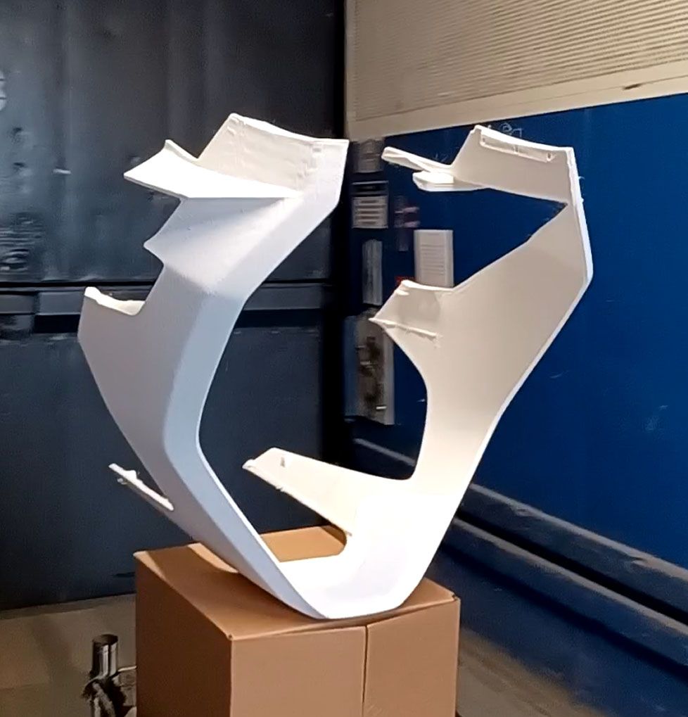
      Or mostly a success. Definitely a usable part for initial track testing but the print does have some blemish areas.

      I added Z hopping at 1mm so there was a ton of z motion going on but it did not affect the print time that much. The Z motor was a lot hotter. I may have to tune the retraction settings now as at some points it seemed to be depositing a tiny drop of material, z hopping to a couple mm away, and repeating for 30-50 times in a row. I am not getting any blobbing or stringing issues, so likely have some margin to reduce retractions.

      The added z motion did accentuate the instability of really tall (500mm+) and slender support structures, as you could see them swaying back and forth a bit. Once the printhead was printing on them the motion was quickly damped, but it has a noticeable effect on surface print quality. I think the fast accelerations of the printer are causing problems when the center of mass of the printed plastic for an island is not over its center of support, so when I create these new CAD supports will try to either prevent that situation or try to give the added bracing some torsional stability. I found that adding 1 perimeter wall option to the support generation adds a lot of stability to the support islands, but it also greatly increases print time and support removal difficulty.

      inner-supports.jpg

      I think most browsers should play this video: https://www.instagram.com/p/CfKd1oqDCpV/

      The part ran with a bunch of Cura generated supports around a bunch of 3 pass wide brace walls that were added to the CAD model in Creo. The uppermost horizontal walls were a bit wonky as a result of my added walls ending too soon and the Cura supports wobbling a bit. This wonkiness stopped when these islands were merged into the overall part perimeter, which was pretty stable due to the CAD added bracing.

      hm-1.jpg

      So these parts are all good enough for initial assembly, dyno and track testing, but there will definitely be a round 2 once that all happens. When I do this part again (and actually for some other parts too), the supports will be revised to something like this:

      inner-rev3.jpg

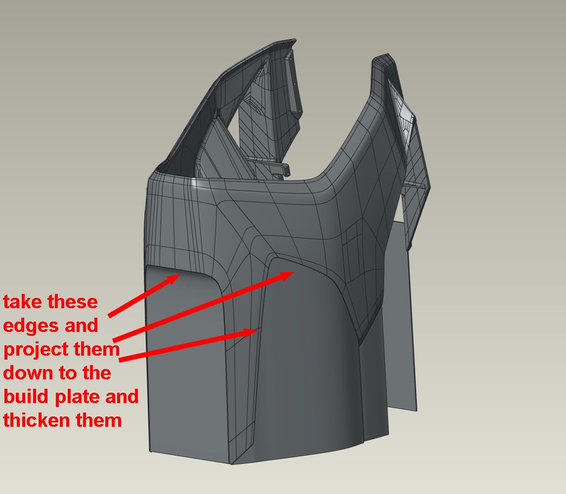
      Basically, after orienting the part I will take the edges that are above the build plate, drape them down to intersect the build plate, then thicken them to 3 print passes. This will eliminate any isolated islands on the print bed and it will also convert the part from long, spindly and unstable fingers and supports to a stable closed profile with few supports. The rest of the fairing is about 5mm thick, and done with 2 walls and 10% gyroid infill. The result is that the added walls are 'solid' where they merge into the part so can be trimmed off without breaking through to the infill. The added part volume seems to be a decent amount less than the support structure it is replacing, and because they are usually long smooth print moves can be done at a consistent realized 150mm/sec, so also print decently faster than constantly reversing support movement.

      I found that cutting these style ribs off was pretty easy with an oscillating handheld cutters (dremel mm35). No melting and with the right blade shape (standard one included in package) it was easy to get near flush cuts. No nicked fingers, either!

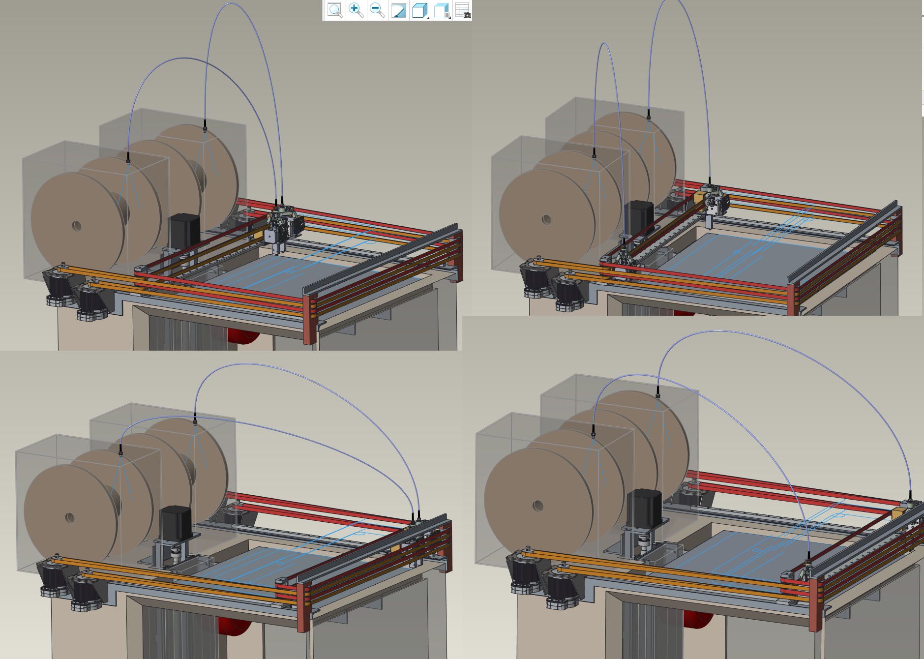
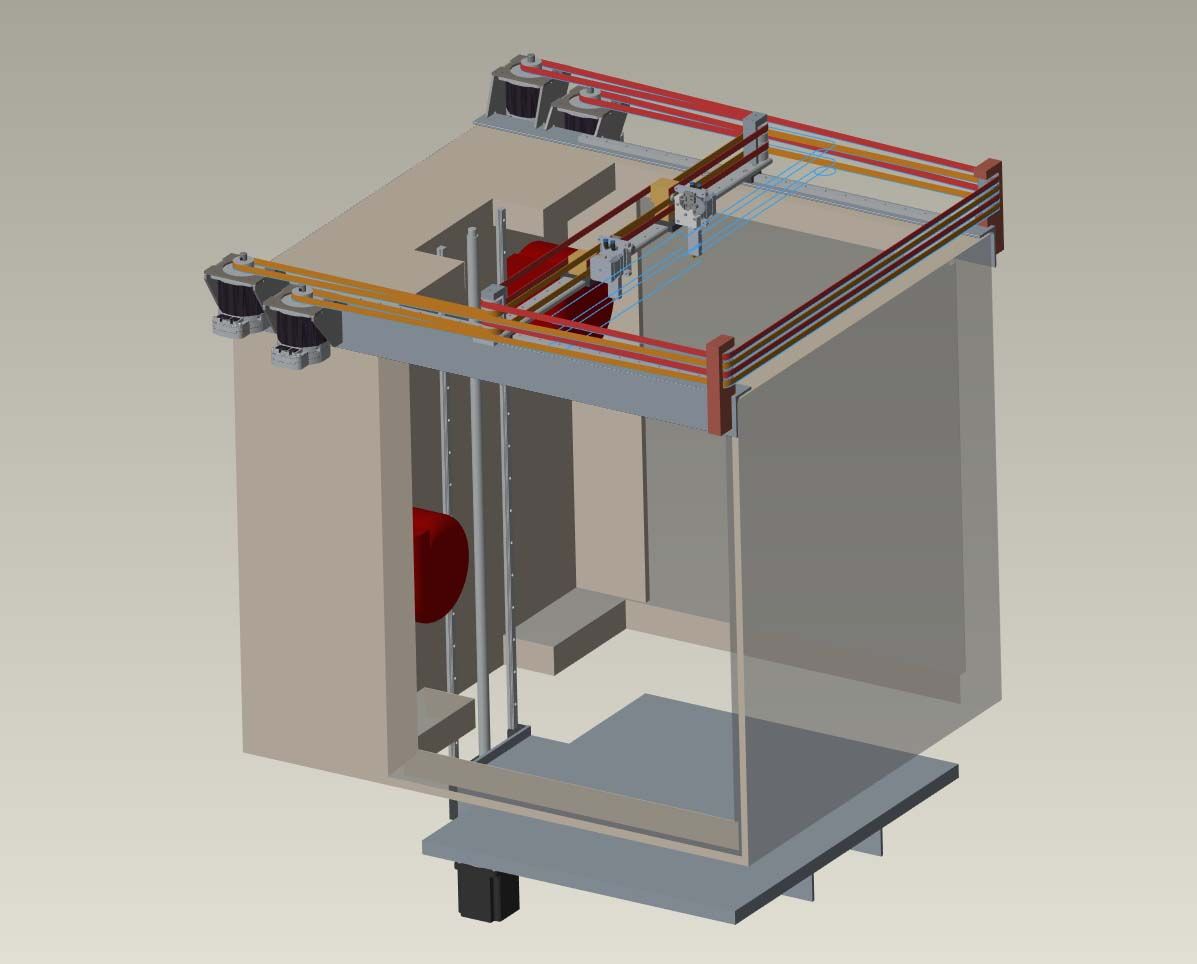
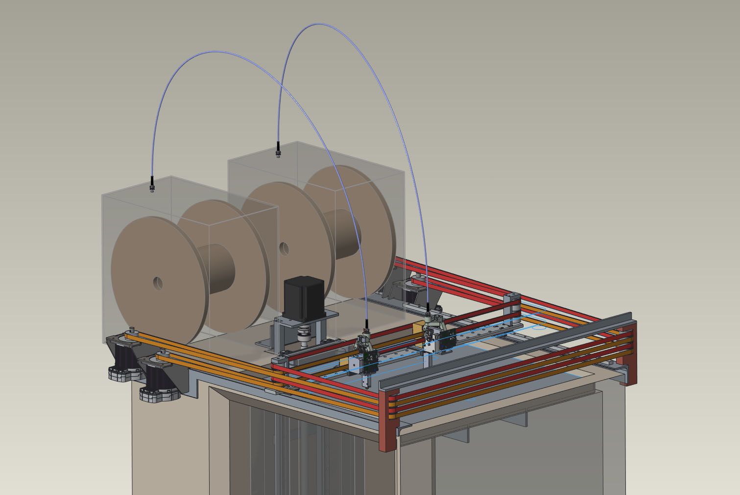
      This last print was 52hrs. The printer has been going almost continually since 5/16 with no more than a few hours between prints. I've gone through about 28kg of filament so far. The only failure was the filament stepper fan, which burned out. Turns out it was a 12V fan running at 24V. I may add some shielding between the chamber heater elements and the build plate, as on the previous failed print it did seem that the heater on one side caused some of the single wall tree supports that were directly opposite it to sag. Other than that, the printer has been mechanically sound, which is great.

      posted in General Discussion
      cosengundefined
      coseng
    • RE: New heated enclosure printer

      Happy 4th of July everybody.

      Those laydown prints of the front upper sides worked well. Here's a pic of the nearly finished product. All the red, white, and blue body panels were printed out. And the black seat 'pads'.

      20220704_154407.jpg

      I'm going to keep refining the slicer settings and printing more parts as I make updates to the design, but for now can consider this a completely successful printer build project.

      Thanks to the forum for all the suggestions and to the Duet3D crew for such an excellent product line.

      posted in General Discussion
      cosengundefined
      coseng
    • RE: New heated enclosure printer

      It's been a while, the printer has been working well, but am about to do another run of fairings so am going to try to improve it a bit.

      There is some waviness to tall and slender parts that increases as the parts get slimmer and taller in Z. Looking at it while printing, it seems that my construction of a carbon fiber Z carriage works against me in one way. I used high temp CF for its rigidity and low thermal expansion and high enough temp rating. This means that my Z carriage is pretty light, and at high printhead accelerations, can see a slight bit of movement that comes from not enough torsional stiffness of my z-axis rail/leadscrew wended frame. 20+ inch parts can get a visible wiggle at the top as the vibrations die down. I am not interested in tearing it all apart and having to do welding and realignment/reassembly, so am going to try to take the easy way out by putting a large steel weight on the bottom of the z carriage. A heavier carriage means less reaction displacement for a given printhead acceleration, hopefully stabilizing it and reducing the waviness. It is an easily done and undone modification, so pretty low risk.

      The waviness I am getting is not stepper induced oscillations as I am using servo/steppers which are silent and smooth.

      posted in General Discussion
      cosengundefined
      coseng
    • RE: Time line for Duet 3 6XD

      FYI, from @dc42 on 7/26/22:

      The first production 6XD boards are being shipped to resellers this week.

      posted in Using Duet Controllers
      cosengundefined
      coseng
    • RE: New heated enclosure printer

      @jens55 OK, thanks. Also received a reply from the BLTouch people:

      BLTouch can misunderstand the servo signal when the chamber temperature is over 65C. And an extension to the BLTouch push-pin is a good idea, but because it is not tested I can't surely tell you it might be okay. It might be better that you find a proper weight for your BLTouch by trial and error.

      That sounds promising, a tiny CF rod should do it.

      Chris

      posted in General Discussion
      cosengundefined
      coseng
    • RE: New heated enclosure printer

      Making some progress with the build. It is all stripped down, the lower section is newly insulated, and the top section has the pass-through hole in the bottom cut. That hole makes it one big chamber for almost 1m of Z travel, 0.68m and 0.72m for XY.

      printer-progress.jpg

      We'll flip it and cut the same hole in the top which the motion subassembly will drop down into and be closed off with a y-axis bellows.

      cad-061521.jpg

      Each motor pair/y axis rail/belt pulley assembly base will be a rigid steel 2x3" angle that will be milled flat and mounted along the top of the housing. Each of these will be carefully aligned to keep everything parallel. The Z axis stage will be a separate assembly that bolts to the back wall of the chamber.

      posted in General Discussion
      cosengundefined
      coseng
    • RE: New heated enclosure printer

      Doing a little detail work and came across a potential problem. Its a big printer so I wanted to use a big spool, 5 or 10kg per extruder. The spools would be on top of the printer in a sealed box riding on ball bearings with a teflon tube and a (not shown in CAD) spring 'skyhook' to keep the filaments, water cooler lines, and wiring somewhat tidy and controlled.

      spool-feed.jpg

      The filament direct drive is a E3D Titan Aqua with the standard stepper motor. A 10kg spool is a lot of mass to turn, and with the 50" or so of teflon tube will be a bit of friction in there. I'm thinking the filament drive motor may be hard pressed to keep up. There are two larger filament steppers available from E3D but I only have the 1.1A stepper driver on the 1LC toolboards to drive it. The 1LC is being fed with 24VDC.

      Any thoughts on if I need to do something else here to prevent filament starvation problems?

      posted in General Discussion
      cosengundefined
      coseng
    • RE: New heated enclosure printer

      @mrehorstdmd A few years ago I had a client project that needed a swappable fiber optic switchboard and we went through several design iterations with and without feed tubes before getting one without feed tubes and with a spring loaded retract system that worked for ~1M cycles. So I've a bunch of relevant experience with the situation!

      20210709_120041.jpg

      posted in General Discussion
      cosengundefined
      coseng
    • RE: New heated enclosure printer

      Sorry not to update more but a bit busy on other parts of the bike project. The bellows from Centryo came in and looks nice as did some waterjet cut parts for the XYUV motor mounts.

      20210719_210210.jpg

      I'll try to get the Z axis armature fabricated this weekend, then next week my helper will start laying out the PCBs on a panel so that we can power up and test axis by axis as they are installed.

      posted in General Discussion
      cosengundefined
      coseng
    • RE: New heated enclosure printer

      I finished most of the fab on the XYUV axis assembly and just have top weld up some adjustable mounting brackets to weld to the top of the enclosure.

      So far so good with the rough alignment and the X axis rail seems stiff enough on its own.
      20210817_232359.jpg

      20210817_232938.jpg

      20210817_232930.jpg

      Its about to start getting together pretty quickly, then commissioning and setup of the Duet Hardware happens.

      posted in General Discussion
      cosengundefined
      coseng
    • RE: New heated enclosure printer

      Some more progress on the XYUV axis assembly with bracing done and XY belts installed. I made all the long braces from steel to match expansion rates with the linear motion components. This thing will move around enough when it heats up, I'd rather not have to deal with twisting due to differential thermal expansions.

      A little tweaking is needed to keep the belts happy but nothing major. Not sure if I will need some idler pulleys on the long runs to prevent vibrations. Now it is just sitting on top of the enclosure and points are being marked to weld in the mounting/alignment system.

      20210824_123220.jpg

      posted in General Discussion
      cosengundefined
      coseng
    • RE: New heated enclosure printer

      Making some small progress on the printer in between a bit of actual paying work!

      For a little cross-pollination, I used my LCD resin printer with Siraya Sculpt Ultra White high temp resin to print a bracket for the printhead that holds the PCB, BL Touch, water cooling lines and filament tube anchor. It sits on top of the heated chamber, so didn't want to use a normal FDM plastic part.

      20210906_214639.jpg

      The resin says good to 220C. It was tested to about 130C with a 30 min soak, well higher than it should ever experience. I loaded it a bit by pushing on it while at temp in the oven, and was impressed by the part's strength. When cool, it feels just like Bakelite.
      flir_20210906T205154.jpg

      I have to print another one due to forgetting a wire harness feature, so will put the old one in and test as hot as my toaster over will go to see if I can get a failure.

      posted in General Discussion
      cosengundefined
      coseng
    • RE: New heated enclosure printer

      OK, the Z carriage is assembled and mounted and super rigid.
      20220311_180419.jpg

      Access for removing large parts should be good.
      20220311_180349.jpg

      Now that all the mechanics are at least installed, next week it is time to mount up all the power and control electronics and start wiring this baby up!

      posted in General Discussion
      cosengundefined
      coseng
    • RE: New heated enclosure printer

      My sense of timing is spot on, just as things get close to completion, I break my left collarbone. And I'm a leftie. Oh well, slow progress is still progress, right?

      One armed is still enough to work on the electronics, so last week I was able to mount all the components and get most of the AC and DC lines wired up.

      SSR control for the internal fan/heater assemblies and the Keenovo AC bed heater. Standard 24VDC AC/DC power supply for all the logic, fans, small heaters, and a switching 75VDC motor power supply with external capacitor for absorbing back-generation.

      electronics.jpg

      Today I finished the roach wiring to the back of the 6HC board to tap the step and direction signals for stepper drivers 1-4. The ribbon connector is permanently epoxied in place. It is not the neatest modifications but the solder connections seem strong and nothing is shorted. I am curious about the solder used for the DC in terminals, it seemed a lot higher melt temp than for the signal lines.
      6hc-ext-stepper-mod.jpg

      I'll run a 50 pin flat cable from this hacked connector to the Duet 2 BoB to get the 5V signals that the ClearPath motors want to see.

      I have an assistant coming in for the next few days so hopefully he can get the aluminum bed and leveling mounts machined and mounted so I can then install the bed heater lines, power up the electronics and do initial commissioning and alignment. And fixing any wiring errors!

      posted in General Discussion
      cosengundefined
      coseng
    • RE: New heated enclosure printer

      @coseng Actually, I have a paneldue 7i 2.01, so the card detect signal is present, so the last question is no longer relevant.

      posted in General Discussion
      cosengundefined
      coseng
    • RE: New heated enclosure printer

      Progress! All the axes work and no more errors. And yes, thermistors for the chamber temp sensor. I have not done the thermal tuning for any of the heaters yet, but am expecting the chamber to take a while. Are there timeouts? I can't imagine the chamber coming up to temp quickly.

      The from an aural perspective, the clearpath motors are light years ahead of steppers. Compared to the steppered Z axis, they are fast and quiet, and with the long belt runs (about 3ft.) there are no problems with belt span weirdness from really slow moves to nearly 2000ipm/0.9mps rapids. Yes, 2000ipm, that is not an extra zero. I know that it will never print at those speeds, but is nice to know that there is plenty of torque to spare and that the mechanical structure has the stiffness to deal with large acceleration forces. I was surprised that the bellows was not a limiting factor. I had Tom Tullar from Teknic remotely tune the motor parameters and he was very happy with the results, with a very small following error even during accelerations. The software is pretty awesome, their diagnostic oscilloscope feature is very useful and showed very good axis alignment by having a consistent torque requirement along the entire axis length.

      Here's a short video of some motion:

      https://youtube.com/shorts/0DkGP00Besg?feature=share

      I am really impressed with the overall quality of entire the Duet ecosystem. The hardware,firmware, software, and user support were all top quality. It is not often that I can't find something that could be improved, but this is one of those times! It makes me want to build more stuff with it!

      Now on to getting it hot and printing!

      posted in General Discussion
      cosengundefined
      coseng