@ander , I made all my videos private, but I forgot I had those 2 videos shared here, I made them public again
Posts made by CVMichael
-
RE: 3D scanning a $2 coin with 3D printer and DIY touch probeposted in My Duet controlled machine
-
RE: Duet 3 Mini5+ not heating the extruderposted in General Discussion
@Phaedrux
Here is the version from DWC
Board: Duet 3 Mini 5+ (Mini5plus)
Firmware: RepRapFirmware for Duet 3 Mini 5+ 3.4.5 (2022-11-30)
Duet WiFi Server Version: 1.26; General preferences G90 ; send absolute coordinates... M83 ; ...but relative extruder moves M550 P"Mendel90" ; set printer name ; Network M552 S1 ; enable network M586 P0 S1 ; enable HTTP M586 P1 S0 ; disable FTP M586 P2 S1 ; enable Telnet ; Drives M569 P0.0 S0 ; Y M569 P0.1 S1 ; Z M569 P0.2 S0 ; Z M569 P0.3 S0 ; X M569 P0.4 S1 ; E M584 X0.3 Y0.0 Z0.1:0.2 E0.4 ; set drive mapping M350 X16 Y16 Z16 E16 I1 ; configure microstepping with interpolation M92 X80.00 Y80.00 Z3200.00 E873.08 ; set steps per mm M566 X900.00 Y900.00 Z60.00 E120.00 ; set maximum instantaneous speed changes (mm/min) M203 X40000.00 Y40000.00 Z700.00 E1200.00 ; set maximum speeds (mm/min) M201 X4000.00 Y4000.00 Z40.00 E250.00 ; set accelerations (mm/s^2) M906 X1000 Y1000 Z1000 E1000 I30 ; set motor currents (mA) and motor idle factor in per cent M84 S30 ; Set idle timeout ; Axis Limits M208 X0 Y0 Z0 S1 ; set axis minima M208 X200 Y200 Z194.5 S0 ; set axis maxima ; Endstops M574 X1 S1 P"io3.in" ; configure switch-type (e.g. microswitch) endstop for low end on X via pin io3.in M574 Y1 S1 P"io6.in" ; configure switch-type (e.g. microswitch) endstop for low end on Y via pin io6.in M574 Z2 S1 P"io5.in" ; configure switch-type (e.g. microswitch) endstop for high end on Z via pin io5.in ; Z-Probe M558 P0 H5 F120 T6000 ; disable Z probe but set dive height, probe speed and travel speed M557 X15:200 Y15:195 S20 ; define mesh grid ; Heaters M308 S0 P"temp0" Y"thermistor" T100000 B4138 ; configure sensor 0 as thermistor on pin temp0 M950 H0 C"out0" T0 ; create bed heater output on out0 and map it to sensor 0 ;M307 H0 B1 S1.00 D30 ; enable bang-bang mode for the bed heater and set PWM limit M307 H0 R0.201 K0.376:0.000 D3.19 E1.35 S1.00 B0 M140 H0 ; map heated bed to heater 0 M143 H0 S100 ; set temperature limit for heater 0 to 100C M308 S1 P"temp1" Y"thermistor" T100000 B4138 ; configure sensor 1 as thermistor on pin temp1 M950 H1 C"out1" T1 ; create nozzle heater output on out1 and map it to sensor 1 M307 H1 B0 S1.00 ; disable bang-bang mode for heater and set PWM limit M143 H1 S280 ; set temperature limit for heater 1 to 280C ; Fans M950 F0 C"out3" Q500 ; create fan 0 on pin out3 and set its frequency M106 P0 S0 H-1 ; set fan 0 value. Thermostatic control is turned off M950 F1 C"out4" Q500 ; create fan 1 on pin out4 and set its frequency M106 P1 S1 H1 T45 ; set fan 1 value. Thermostatic control is turned on ; Tools M563 P0 D0 H1 F0 ; define tool 0 G10 P0 X0 Y0 Z0 ; set tool 0 axis offsets G10 P0 R0 S0 ; set initial tool 0 active and standby temperatures to 0C ; Custom settings are not defined ; Miscellaneous M911 S10 R11 P"M913 X0 Y0 G91 M83 G1 Z3 E-5 F1000" ; set voltage thresholds and actions to run on power loss -
RE: Duet 3 Mini5+ not heating the extruderposted in General Discussion
New Update:
When I issue command "M109 S100" it works! it's heating up!
But! when I select the temperature from the drop down menu in DWC, it does not work!What M code does DWC send when selecting a temperature ? how do I edit that ?
-
RE: Duet 3 Mini5+ not heating the extruderposted in General Discussion
Since my previous post, I also tried to connect to OUT 2 and changed "M950 H1 C"out2" T1", and it still did not work.
To make sure that my heater is OK, I connected the heater wires directly to 12V of my power supply, the heat was going up pretty fast, and the DWC was showing the temperature going up also.
Forgot to show my board firmware in my previous post:
FIRMWARE_NAME: RepRapFirmware for Duet 3 Mini 5+ FIRMWARE_VERSION: 3.4.5 ELECTRONICS: Duet 3 Mini5plus WiFi FIRMWARE_DATE: 2022-11-30 19:41:16Please help! i'm out of ideas
-
Duet 3 Mini5+ not heating the extruderposted in General Discussion
I don't know what is happening, I plugged the heater in the "OUT 1" but the Duet 3 is not giving power when I set a temperature in the DWC.
I measured the wires, it gives me 4 ohms (when the printer is off).
I turn on printer, and set a temperature, and I measure for volts, and nothing, 0 volts.Here are my settings for the nozzle heater:
M308 S1 P"temp1" Y"thermistor" T100000 B4138
M950 H1 C"out1" T1
M307 H1 B0 S1.00
M143 H1 S280
The thermistor works because it shows room temperature, and when I heat the nozzle (with a soldering iron for example), then the DWC shows the temperature rising
-
DuetWifi static IPposted in General Discussion
I'm tying to setup a static IP because almost every time I turn on the printer it gets new IP.
I entered this in the config.g; Network M540 P0xCE:0xAF:0xAA:0xAC:0xFC:0x38 ; MAC Address M550 P"Printer400" ; Set machine name M552 S1 ; Enable network M552 P192.168.0.10 ; (0 = DHCP) M554 P192.168.0.1 ; Gateway M553 P255.255.255.0 ; Netmask M587 S"xxxxxxxxx" P"yyyyyyyyy" ; Configure access point. You can delete this line once connected M586 P0 S1 ; Enable HTTP M586 P1 S0 ; Disable FTP M586 P2 S1 ; Disable TelnetBut it does not seem to make any difference, it still gets a random IP
-
RE: Upgraded firmware to rrf 3.01-RC1, lots of problemsposted in General Discussion
For M581, I just could not get it to trigger with exp.e6stop on the Duex5
; Configure external trigger - big red button
M581 P"^exp.e6stop" T0 C0
So in the end I unplugged the wire, and connected it to zstop, and now it triggers, BUT!!! once triggered, I don't know if it keeps triggering, or not being able to connect back, because the only way to get my printer working again, is to power it off, and back on. This is the command I am using:
; Configure external trigger - big red button
M581 P"^zstop" T0 C0
For filament sensing, I still did not get the chance to test it, but I changed it to:
M591 D0 P7 C"connlcd.3" S1 R50:150 L0.305 E5Hoping that it is correct.
For Camera logical pins, command M42, I can't find a chart or something with the equivalent pins.
This is the old chart I used:
https://duet3d.dozuki.com/Wiki/Using_servos_and_controlling_unused_IO_pins#Section_Duet_2_WiFi_and_Duet_2_Ethernet
I can't see the pin names "GPIO pins 1-4" in here:
https://duet3d.dozuki.com/Wiki/RepRapFirmware_3_overview#Section_Pin_names_for_Duet_2_WiFi_Ethernet
For M42 P62 S0, I think the pin name is "spi.cs7", right? -
RE: Upgraded firmware to rrf 3.01-RC1, lots of problemsposted in General Discussion
I Fixed endstops, Z-Probe, Fans, Heaters
I changed M581, but does not work, it does not trigger.
Filament sensing, changed but did not try it yet, I don't know if "e10stop" is correct
For Heaters, I have no idea if I put the correct numbers, but it seems to workconfig.g:
; Drives
M584 X7 Y5:6 Z1:2:3:4 E0 P3
M569 P0 S1                                      ; Drive 0 goes forwards
M569 P1 S1                                      ; Drive 1 goes forwards
M569 P2 S1                                      ; Drive 2 goes forwards
M569 P3 S1                                      ; Drive 3 goes forwards
M569 P4 S1                                      ; Drive 4 goes forwards
M569 P5 S0                                      ; Drive 5 goes forwards
M569 P6 S0                                      ; Drive 6 goes forwards
M569 P7 S0                                      ; Drive 7 goes forwards
M569 P8 S0                                      ; Drive 8 goes forwards
M569 P9 S0                                      ; Drive 9 goes forwards
M569 P10 S1                                      ; Drive 10 goes forwards

M350 X16    Y16:16       Z16     E16 I1         ; Configure microstepping with interpolation
M92  X160   Y160:160     Z2667   E203           ; Set steps per mm
M566 X900   Y900:900     Z10     E300           ; Set maximum instantaneous speed changes (mm/min)
M203 X40000 Y40000:40000 Z300    E3600          ; Set maximum speeds (mm/min)
M201 X1000  Y1000:1000   Z50     E10000         ; Set accelerations (mm/s^2)
M906 X1500  Y1500:1500   Z1500   E1500 I50      ; Set motor currents (mA) and motor idle factor in per cent
M671 X-82:-82:482:482 Y0:400:400:0 S5             ; Z leadscrews are at (-82, 0), (-82, 400), (482, 400), (482, 0)
M84 S30                                            ; Set idle timeout
M572 D0 S0.1                                       ; pressure advance
M204 P400 T1000                                    ; Lower accelerations when printing

; Axis Limits
M208 X0 Y0 Z0 S1                                   ; Set axis minima
M208 X400 Y400 Z400 S0                             ; Set axis maxima

; Endstops
M574 X1 S1 P"xstop"   ; X min active high endstop switch
M574 Y1 S1 P"ystop"   ; Y min active high endstop switch


; Z-Probe
M574 Z1 S2                             ; Set endstops controlled by probe
M558 P9 C"^zprobe.in" H5 F800 T3000  	; BLTouch connected to Z probe IN pin
M950 S0 C"duex.pwm5" 			; create servo/gpio 0 on heater 3 pin on expansion connector
G31 P500 X0 Y25 Z2.00                   ; Set Z probe trigger value, offset and trigger height, probe offset for 0.4 mm Cyclops Switching Hotend Extruder 2 in 1 Out
M280 P0 S90
M557 X30:380 Y30:380 S70                ; Define mesh grid


; Heaters
M308 S0 P"bed_temp" Y"thermistor" T100000 B4138		; define bed temperature sensor
M308 S1 P"e0_temp"  Y"thermistor" T100000 B4725 C7.06e-8 ; define E0 temperature sensor
M950 H0 C"bed_heat" T0 					; heater 0 uses the bed_heat pin, sensor 0
M950 H1 C"e0_heat" T1					; heater 1 uses the e0_heat pin and sensor 1


; Fans
M950 F0 C"fan0" Q100
M950 F1 C"fan1" Q500
M950 F2 C"duex.fan3" Q500

M106 P1 C"Filter 1"
M106 P2 C"Filter 2"


; Tools
M563 P0 D0 H1 S"NO TOOL"                           ; Define tool 0
G10 P0 X0 Y0 Z0                                    ; Set tool 0 axis offsets
G10 P0 R0 S0                                       ; Set initial tool 0 active and standby temperatures to 0C

; Automatic power saving
M911 S10 R11 P"M913 X0 Y0 G91 M83 G1 Z3 E-5 F1000" ; Set voltage thresholds and actions to run on power loss

; Configure external trigger - big red button
M581 P"exp.e6stop" T0 C0

; Configure filament sensing (Extruder 0, pulse-generating sensor, E0, enable filament monitoring)
M591 D0 P7 C"e10stop" S1 R50:150 L0.305 E5

; Camera logical pins
M42 P100 S0 ; start taking picture every 6 seconds
M42 P101 S0 ; start taking picture every 4 seconds
M42 P102 S0 ; camera off
M42 P103 S0 ; start taking picture every 2 seconds
M42 P60 S0  ; not used yet
M42 P61 S0  ; not used yet
M42 P62 S0  ; take one picture now (for layer change)

; M98 P"0:/macros/Tools/Set Tool 2"

; Miscellaneous
T0                                                 ; Select first tool
I'm done for today, I'll try to fix the rest tomorrow. In the mean time, if someone could take a look at my new code and let me know if you see some problems?
Thanks!
-
RE: Upgraded firmware to rrf 3.01-RC1, lots of problemsposted in General Discussion
I don't want to downgrade, I want to make my printer work with the latest firmware
-
Upgraded firmware to rrf 3.01-RC1, lots of problemsposted in General Discussion
I didn't upgrade the firmware for a long time, last one I had was 2.02(RTOS)(2018-12-24b1)
Now I have:
Board: Duet WiFi 1.02 or later + DueX5
Firmware: RepRapFirmware for Duet 2 WiFi/Ethernet 3.01-RC1 (2020-02-08b3)
Duet WiFi Server Version: 1.23BLTouch does not work anymore, extra fans don't work anymore, tools I think I have a problem there too
BLTouch is connected to Z PROBE IN, and PWM5 (E6_PWM) on DueX5
I have to extra fans on Fan1, and Fan3 on DueX5
Fan 1 seems to work, but it's either on or off, and Fan 3 does not workFor tool, I have 6 tools that I can change on the printer, so I define that in separate macros, but I want to setup a default one named "NO TOOL" to let me know that I have to select a tool from a macro depending on what tool I have attached to the printer. In the macro I override previous tools
I am new to rrf 3, I tried to search the new way of doing things, but I am having a hard time
; Drives M584 X7 Y5:6 Z1:2:3:4 E0 P3 M569 P0 S1 ; Drive 0 goes forwards M569 P1 S1 ; Drive 1 goes forwards M569 P2 S1 ; Drive 2 goes forwards M569 P3 S1 ; Drive 3 goes forwards M569 P4 S1 ; Drive 4 goes forwards M569 P5 S0 ; Drive 5 goes forwards M569 P6 S0 ; Drive 6 goes forwards M569 P7 S0 ; Drive 7 goes forwards M569 P8 S0 ; Drive 8 goes forwards M569 P9 S0 ; Drive 9 goes forwards M569 P10 S1 ; Drive 10 goes forwards M350 X16 Y16:16 Z16 E16 I1 ; Configure microstepping with interpolation M92 X160 Y160:160 Z2667 E203 ; Set steps per mm M566 X900 Y900:900 Z10 E300 ; Set maximum instantaneous speed changes (mm/min) M203 X40000 Y40000:40000 Z300 E3600 ; Set maximum speeds (mm/min) M201 X1000 Y1000:1000 Z50 E10000 ; Set accelerations (mm/s^2) M906 X1500 Y1500:1500 Z1500 E1500 I50 ; Set motor currents (mA) and motor idle factor in per cent M671 X-82:-82:482:482 Y0:400:400:0 S5 ; Z leadscrews are at (-82, 0), (-82, 400), (482, 400), (482, 0) M84 S30 ; Set idle timeout M572 D0 S0.1 ; pressure advance M204 P400 T1000 ; Lower accelerations when printing ; Axis Limits M208 X0 Y0 Z0 S1 ; Set axis minima M208 X400 Y400 Z400 S0 ; Set axis maxima ; Endstops M574 X1 Y1 S1 ; Set active high endstops ; Z-Probe ;M574 Z1 S2 ; Set endstops controlled by probe ;M307 H7 A-1 C-1 D-1 ; Disable heater on PWM channel for BLTouch ;M558 P9 H5 F800 T6000 ; Set Z probe type to bltouch and the dive height + speeds ;;G31 P500 X0 Y25 Z1.85 ; Set Z probe trigger value, offset and trigger height, probe offset for 0.8 mm nozzle extruder ;; the larger the Z # is, the more squished the first layer is ;G31 P500 X0 Y25 Z2.00 ; Set Z probe trigger value, offset and trigger height, probe offset for 0.4 mm Cyclops Switching Hotend Extruder 2 in 1 Out ;M557 X30:380 Y30:380 S70 ; Define mesh grid M574 Z1 S2 ; Set endstops controlled by probe M307 H7 A-1 C-1 D-1 ; Disable heater on PWM channel for BLTouch M558 P9 C"^zprobe.in" H5 F120 T3000 ; BLTouch connected to Z probe IN pin M950 S0 C"exp.heater3" ; create servo/gpio 0 on heater 3 pin on expansion connector G31 P500 X0 Y25 Z2.00 ; Set Z probe trigger value, offset and trigger height, probe offset for 0.4 mm Cyclops Switching Hotend Extruder 2 in 1 Out M280 P3 S10 I1 ; send control signal to BLTouch through heater 3 pin M557 X30:380 Y30:380 S70 ; Define mesh grid ; Heaters M307 H0 B0 S1.00 ; Disable bang-bang mode for the bed heater and set PWM limit M305 P0 T100000 B4138 R4700 ; Set thermistor + ADC parameters for heater 0 M143 H0 S140 ; Set temperature limit for heater 0 to 140C M305 P1 T100000 B4138 R4700 ; Set thermistor + ADC parameters for heater 1 M143 H1 S280 ; Set temperature limit for heater 1 to 280C M950 F0 C"fan0" Q100 M950 F1 C"fan1" Q100 M950 F2 C"fan2" Q100 ; Fans M106 P0 S0 I0 F500 H-1 ; Set fan 0 value, PWM signal inversion and frequency. Thermostatic control is turned off M106 P1 S0 I0 F500 H-1 ; Set fan 1 value, PWM signal inversion and frequency. Thermostatic control is turned Off M106 P3 S0 I0 F500 H-1 ; Set fan 1 value, PWM signal inversion and frequency. Thermostatic control is turned Off ; Tools M563 P0 D0 H1 S"NO TOOL" ; Define tool 0 G10 P0 X0 Y0 Z0 ; Set tool 0 axis offsets G10 P0 R0 S0 ; Set initial tool 0 active and standby temperatures to 0C ; Automatic power saving M911 S10 R11 P"M913 X0 Y0 G91 M83 G1 Z3 E-5 F1000" ; Set voltage thresholds and actions to run on power loss ; Custom settings are not configured M581 E6 S1 C0 T0 ; Configure external trigger - big red button ;M581 E6 S1 C0 T2 ; Trigger 2, reset WiFi ;M581 E2 S0 C0 T3 ; testing trigger on E2 ; Configure filament sensing (Extruder 0, pulse-generating sensor, E0, enable filament monitoring) M591 D0 P7 C10 S1 R50:150 L0.305 E5 ; Camera logical pins M42 P100 S0 ; start taking picture every 6 seconds M42 P101 S0 ; start taking picture every 4 seconds M42 P102 S0 ; camera off M42 P103 S0 ; start taking picture every 2 seconds M42 P60 S0 ; not used yet M42 P61 S0 ; not used yet M42 P62 S0 ; take one picture now (for layer change) ; M98 P"0:/macros/Tools/Set Tool 2" ; Miscellaneous T0 ; Select first tool -
RE: Level bed only onceposted in General Discussion
Took me a while to find this:
https://duet3d.dozuki.com/Wiki/GCode_Meta_Commands -
Level bed only onceposted in General Discussion
Right now in my startup gcode in the slicer, I am calling "M98 Pbed.g", but if I print small parts, and many times without restarting the printer; the subsequent levelling is unnecessary, and takes a long time.
This is the gcode in bed.g
M561                ; clear any bed transform
M98 Pdeployprobe.g  ; deploy mechanical Z probe

G30 P0 X0   Y20   Z-99999 ; probe near a leadscrew
G30 P1 X400 Y20   Z-99999 ; probe near a leadscrew
G30 P2 X0   Y380  Z-99999 ; probe near a leadscrew
G30 P3 X400 Y380  Z-99999 S4 ; probe near a leadscrew and calibrate 4 motors

M98 Pretractprobe.g ; retract mechanical Z probe

M98 Phomez.g

M561                ; clear any bed transform
M98 Pdeployprobe.g  ; deploy mechanical Z probe
G29                 ; probe the bed and enable compensation
M98 Pretractprobe.g ; retract mechanical Z probe
Is there a way to tell it: if this is already done, don't do it again ?
-
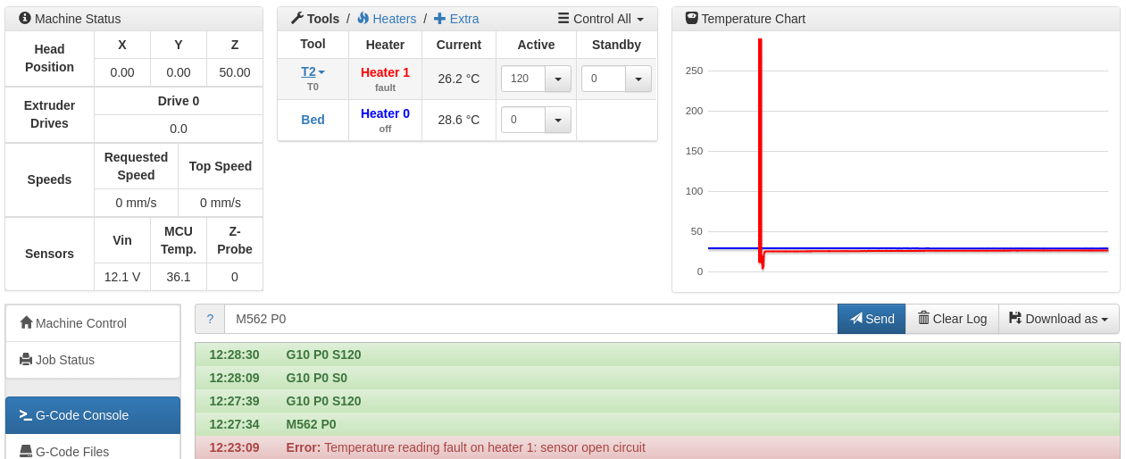
RE: How to reset error: Temperature reading fault on heater 1posted in General Discussion
Just discovered something new.
When I get the error, I send command "M562 P1", and it does not show "fault" anymore, then I use the web interface to change temperature, it sends "G10 P0 S120", and that does not work!
BUT !! If I send command "M104 S120", then it DOES WORK, after the M104, sending G10 P0 S120 (or any other temp) works after that.
So this looks to me like this is a bug in the software
-
RE: How to reset error: Temperature reading fault on heater 1posted in General Discussion
Can't get it to work.
I get the error when I remove the tool, and when I attach a new tool, I clear the error with M562 P0, it shows the temperature, but it's not doing anything when I was to raise the temperature with "G10 P0 S120" for example.
When I remove the tool, thermistor, and heater (and BL-Touch, and fans) gets unplugged, and then a new one is plugged in, I have a few of them
Until now, I always reset the printer, but in the future I want to do automatic tool changer, so I want to figure out this problem
-
RE: How to reset error: Temperature reading fault on heater 1posted in General Discussion
It does not work for me!
23:13:05G10 P0 S0
23:12:58G10 P0 S120
23:12:54G10 P0 S0
23:12:08G10 P0 S120
23:12:04M562 P0
23:12:03M562 P0
23:11:31G10 P0 S180
23:11:29M562 P2
23:11:01G10 P0 S120
23:10:53M562 P0
23:09:37G10 P0 S120
23:09:34M562 P1
23:05:28Error: Temperature reading fault on heater 1: sensor open circuitAfter the error I tried P1, P0, P2, nothing I do makes the heater turn on, even though it shows the correct room temperature (therefore it's connected properly)
-
How to reset error: Temperature reading fault on heater 1posted in General Discussion
How to reset the error "Temperature reading fault on heater 1: sensor open circuit"
When I change the tool, I have to unplug the temperature sensor (it's attached to the tool). I don't want to restart the printer every time I change the tool.
After I change the tool, it shows the temperature (room temp), so the temperature sensor is OK, but I can't heat up the extruder because of the "unplug", and "plug back new one" sensor error.
Is there a way to reset the error?
-
RE: TMC2660 on stepper channels 10 and 11posted in General Discussion
Sorry, but I am still trying to figure out the connections.
"ENN - connect to ENN on the expansion bus" - what pins? I only see "En 10" and "En 11" on the CONN_LCD, but I don't see any 10, 11 on the expansion bus.
"CSN - connect to the corresponding ENABLE pin on CONN_LCD" - is this the "En 10" and "En 11" ?
I am confused between ENN and CSN....
What is the "Stop 10" and "Stop 11" ? pins 3 & 4 on the CONN_LCD, is this for the CSN ?
"SDI, SDO, SCK - connect to SPI1_MOSI, SPI1_MISO and SPI_SCK on the expansion bus" - I already have a Duex5, and I don't see any pins for the SPI1 (I see quite a few for SPI0 though). Does this mean that I will have to sodder wires in the back of the Duet PCB to bring the SPI1 to my motor driver PCB?
Since I want to make a PCB for both channels 10 & 11, I assume SPI is connected in parallel, but CSN is separate?
I created a schematic, if you have some time to take a look at it, and let me know if you see any mistakes:
This is the driver hierarchy block:

and this is the main schematic / connections:

I made the schematic in DipTrace, if you want me to upload the DipTrace file, let me know.
Also, I am novice at electronics, so please forgive me if it does not look professional")
I will also design the PCB once I know the schematic is correct. I can upload all the files if anyone else is interested to do this.
-
RE: CNC Mode, Z normally open touch home & meshposted in General Discussion
Is there a way to put an IF statement to omit those g code if a flag is raised?
Kind of like "#define flag" and then "if else" in the deployprobe.g and retractprobe.g file, just like in C/C++ ?
-
RE: CNC Mode, Z normally open touch home & meshposted in General Discussion
Hi dc42,
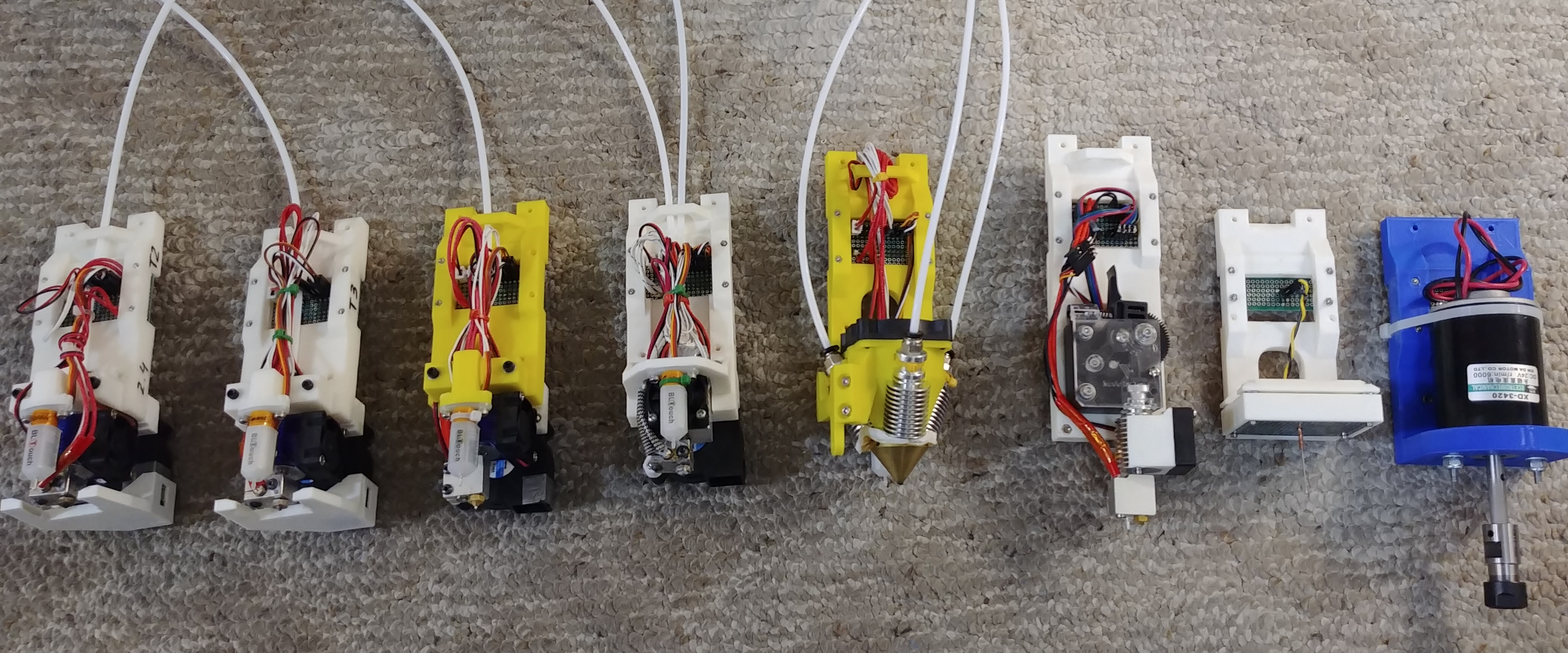
Yes, I do have the deployprobe.g and retractprobe.g with M280 gcode in those files, but the problem is that I need those files because I also have tools for 3D printing, actually I have 8 tools in total:

I use BL-Touch on the first 6 (first 4 the BL-Touch is in front, the next 2 are in the back so they are obstructed in this image), number 7 is a touch probe (for 3D scanning), and last one is the milling motor that I am trying to use now.