Duet3D Logo Duet3D
    • Tags
    • Documentation
    • Order
    • Register
    • Login
    1. Home
    2. fho
    • Profile
    • Following 0
    • Followers 0
    • Topics 5
    • Posts 17
    • Best 3
    • Controversial 0
    • Groups 0

    fho

    @fho

    5
    Reputation
    1
    Profile views
    17
    Posts
    0
    Followers
    0
    Following
    Joined Last Online

    fho Unfollow Follow

    Best posts made by fho

    • "Print Another" button on the PanelDue

      This is basically a feature request to have a "Print Another" button on the PanelDue.

      In the web interface you get the choice to "Print Another" after a finished or failed print, which accelerates the process if e.g. the first layer failed and you just want to ... "print another". Printing from the SD card menu is not really equivalent as it does not support sorting by modification date and you have to search through (potentially) many files.

      I understand that this is purely a nice-to-have feature, but this came up on reddit and I wanted to bring it to your attention.

      posted in PanelDue
      fhoundefined
      fho
    • RE: Any known issues with drifting inductive probes?

      Well ... that was a false alarm ...

      I checked the height of the sensor and checked the height of the nozzle in the toolhead ... nozzle was below sensor ... so I thought that was fine.

      Turns out the round heat-sink has rattled itself lose over time and the heat-brake should have sat much higher in the cooler.

      Sorry for the fuzz 🙂

      posted in Using Duet Controllers
      fhoundefined
      fho
    • RE: Another Non-Linear Extrusion Post

      One completely tangential side note that came out of the cross-area modeling above is that Curas simple rectangle (layer_height * extrusion_width) model is perfectly viable for lines that have "neighbors" on both sides. The combined extrusion will perfectly fill the space between the lines.

      Where this falls short is at the outer lines, where the rounded corners will overshoot the intended line width. With a target width of 0.4 mm this model predicts an actual extrusion of 0.443 mm which corresponds to a necessary flow rate reduction of ~90% ... which is more or less exactly what I have measured every time I do flow rate calibrations.

      The formula I use for this is:

      target_volume = target_layer_height * target_extrusion_width
      equivalent_circle_to_circle_width = (target_volume - ((0.5 * target_layer_height)^2 * pi)) / target_layer_height
      actual_extrusion_width = equivalent_circle_to_circle_width + target_layer_height
      

      In the end that means that 0.2 mm layer height prints from Cura will always be larger by 0.043 / 2 = 0.0215 mm in the XY plane.

      posted in Tuning and tweaking
      fhoundefined
      fho

    Latest posts made by fho

    • RE: Another Non-Linear Extrusion Post

      I am back with the actual results:

      download.png

      I ran the exact same GCode with M221 and M592 enabled and measured all prints again.

      There seems to be an effect there, at least the 10-30 mm/s range does look flatter to me. But it is hard to say anything definitive compared to the measurement noise.

      On the other hand, if 90 mm/s print speed (~10 mm³/s flow rate) is a hard maximum for the V6 hotends increasing the extrusion rate should not really do anything there. So maybe my calibration routine is somewhat flawed.

      posted in Tuning and tweaking
      fhoundefined
      fho
    • RE: Another Non-Linear Extrusion Post

      One completely tangential side note that came out of the cross-area modeling above is that Curas simple rectangle (layer_height * extrusion_width) model is perfectly viable for lines that have "neighbors" on both sides. The combined extrusion will perfectly fill the space between the lines.

      Where this falls short is at the outer lines, where the rounded corners will overshoot the intended line width. With a target width of 0.4 mm this model predicts an actual extrusion of 0.443 mm which corresponds to a necessary flow rate reduction of ~90% ... which is more or less exactly what I have measured every time I do flow rate calibrations.

      The formula I use for this is:

      target_volume = target_layer_height * target_extrusion_width
      equivalent_circle_to_circle_width = (target_volume - ((0.5 * target_layer_height)^2 * pi)) / target_layer_height
      actual_extrusion_width = equivalent_circle_to_circle_width + target_layer_height
      

      In the end that means that 0.2 mm layer height prints from Cura will always be larger by 0.043 / 2 = 0.0215 mm in the XY plane.

      posted in Tuning and tweaking
      fhoundefined
      fho
    • Another Non-Linear Extrusion Post

      I am trying myself at calibrating the M592 non-linear extrusion feature and ended up with some questions (at the bottom).

      The setup

      I opted to do the measurement "in-print" on some "1-wall, rounded corner testcube spirals" with 0.6 mm wide, overextruded walls.

      Screenshot from 2021-09-27 13-10-23.png

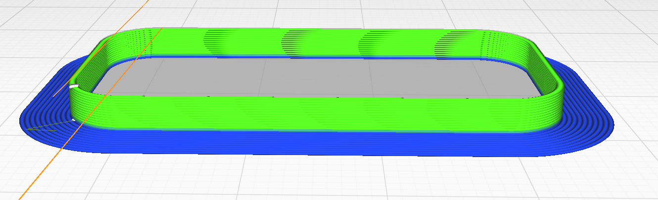
      This should ensure that I am not getting any artifacts due to accelerations and allows me to take several measurements per print speed. Print speeds were varied from 10-90 mm/s corresponding to flow rates of roughly 1-10 mm³/s which should be possible with a stock E3D V6 hotend.

      Each print was measured six times, for a total of 54 measurements.

      The next step might be a bit controversial, but as I used Cura to slice those parts and Cura uses a simple layer_height * extrusion_width model to calculate the required volume I assumed a target width of 0.643 mm to compare the measured extrusion width to:

      Screenshot from 2021-09-27 13-18-03.png

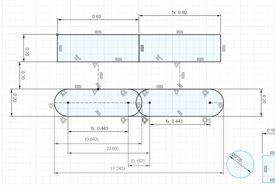
      (both the layer_height * extrusion_width and the "wurst" at the bottom share the same area)

      the results

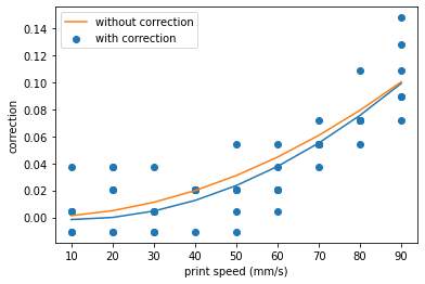
      I did the above several times and I always arrive at negative A factors. E.g:

      Screenshot from 2021-09-27 13-21-52.png

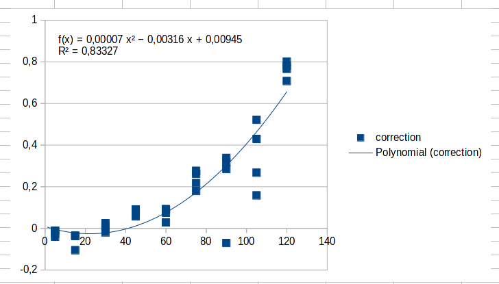
      (The fit uses the A term to adjust for too much extrusion at the lower speeds)

      To mitigate that, I adjusted the flow rates via M221 and fitted another model (this time excluding the C term):

      download.png

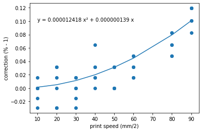
      Judging from that there is somewhat significant underextrusion of about 10% happening in my setup that M592 should be able to mitigate.

      Questions

      1. I assume final_volume = slicer_volume * M221 * (1 + M592), is that correct?
      2. Can we at this point assume that speed and volume correlated with at simple extrusion=B*speed² relation, losing the A factor?
      3. Somewhat tangential, but is my "equal volume" line width calculation above reasonable?
      4. As there are devices that actually measure the amount of extruded filament [1] ... wouldn't they have triggered regularly when confronted with non-linear extrusion. Could they be used in a control loop?

      [1] https://duet3d.dozuki.com/Wiki/Duet3dFilamentMonitor_RotatingMagnetVersion

      posted in Tuning and tweaking filament monitor non-linear extrusion
      fhoundefined
      fho
    • RE: Any known issues with drifting inductive probes?

      Well ... that was a false alarm ...

      I checked the height of the sensor and checked the height of the nozzle in the toolhead ... nozzle was below sensor ... so I thought that was fine.

      Turns out the round heat-sink has rattled itself lose over time and the heat-brake should have sat much higher in the cooler.

      Sorry for the fuzz 🙂

      posted in Using Duet Controllers
      fhoundefined
      fho
    • RE: Any known issues with drifting inductive probes?

      @fcwilt It's the one recommended by the Voron community: https://de.aliexpress.com/item/32803870919.html

      So definitely no-name, but others use it successfully 🤷

      posted in Using Duet Controllers
      fhoundefined
      fho
    • RE: Any known issues with drifting inductive probes?

      @dc42 Thanks for the reply!

      I am aware that inductive sensors are temperature sensitive. I am following the same warm-up procedure every time to mitigate that. That procedure involves letting the (enclosed) chamber warm up for ~20 minutes. I have a temperature sensor in the chamber (and two on the bed), so I am pretty sure that I have a fairly consistent routine there.

      Thing is that even with the routine I seem to have lost several milimeters of "trigger height" over the last week. Paired with the fact that changing the sensor for a "fresh" one does not change that I am searching for other culprits.

      (I am not really suspecting the duet board, just making sure that I covered all possibilities.)

      posted in Using Duet Controllers
      fhoundefined
      fho
    • RE: Any known issues with drifting inductive probes?

      @o_lampe close? Like right next to it 🙈

      Actually when I removed the probe after the printer was off for at least half an hour, the probe still was warm to the touch. The copper coil in there retains a lot of heat.

      Although I do have a silicone sock over the heater block, that should at least prevent some of the heat escaping there.

      posted in Using Duet Controllers
      fhoundefined
      fho
    • RE: Any known issues with drifting inductive probes?

      @o_lampe Fair point ... I'll try that, although my bed does not run in PWM mode. Still that does not really explain why the trigger point apparently drifted gradually over time?

      posted in Using Duet Controllers
      fhoundefined
      fho
    • Any known issues with drifting inductive probes?

      I am a bit at loss here ... last week I ran my Duet 2 Wifi equipped Voron 2.1 basically non-stop on a production run. During the last few prints I noticed that during the bed leveling procedure the nozzle touched the bed once or twice. During the last bed leveling procedure I did, the inductive Z probe I used registered the bed even later/lower and the toolhead bent upwards to "compensate".

      Now, I shrugged that off to a cheap faulty Z probe that just couldn't handle a week at 50°-100°C. I just replaced that with a fresh probe (same model) and that probe has the same problem. For me that rules out the probes themselves.

      Apart from the probes there is only the Duet boards and the bed itself that may be a problem. The bed is a 1 cm lump of cold rolled aluminium... I think that should at most warp at 100°C, but I have no idea what that temperature does to its inductivity (?).

      Just to rule out every possible problem: Are there any known problems with drifting inductive probes on the Duet 2 Wifi boards? (I should look up the version of the board itself ... but the printer is still running 😞 ).

      posted in Using Duet Controllers
      fhoundefined
      fho
    • RE: Can I use a single GND connection to the hotend?

      Ok ... that makes sense 👍

      posted in Duet Hardware and wiring
      fhoundefined
      fho