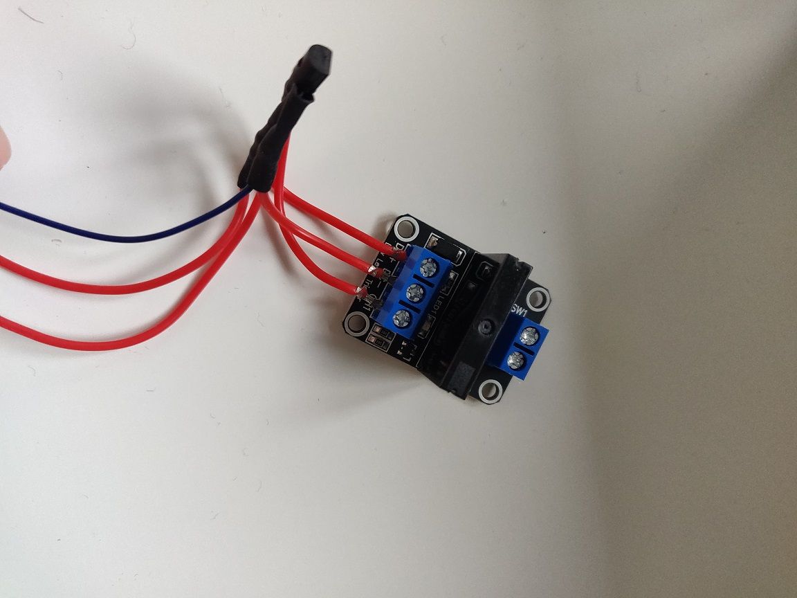
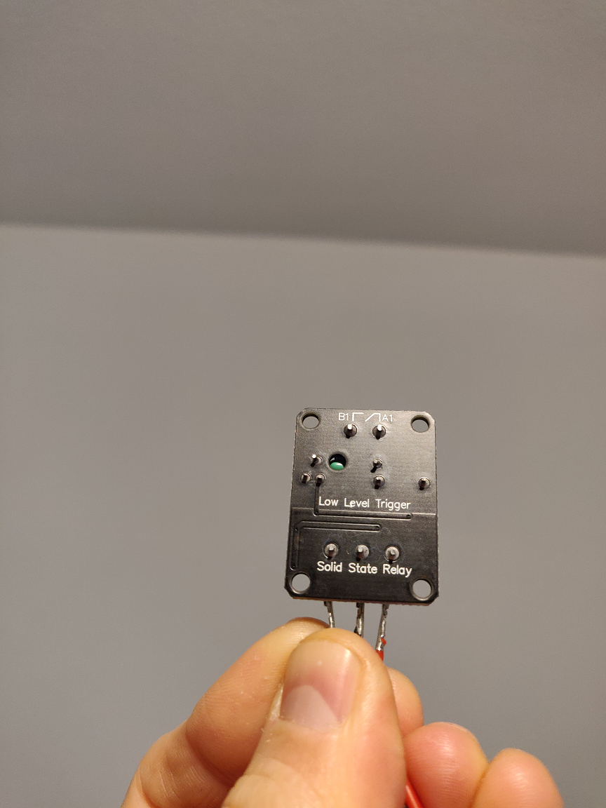
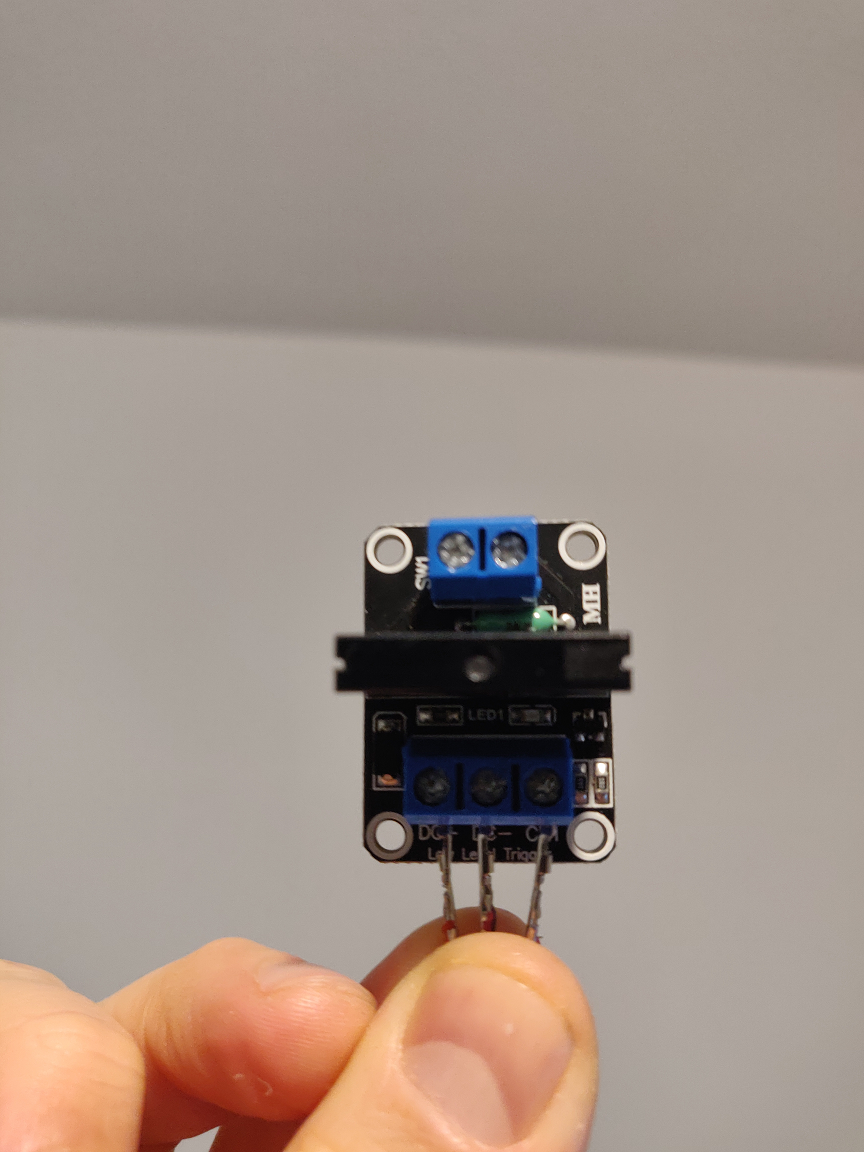
@DIY-O-Sphere It's working! I went to take a picture of my jumper set-up and accidentally "nudged" the cable connecting the 5V pin and PS_ON pin. My PSU turned on... I can now turn it on and off my PSU with M80 and M81 commands. I will double check the connections next time. Thanks a lot for your help, will mark this as resolved.
Posts made by jaclop
-
RE: Duet 3 Mini 5+ controlling Power Supply with SSRposted in Duet Hardware and wiring
-
RE: Duet 3 Mini 5+ controlling Power Supply with SSRposted in Duet Hardware and wiring
@DIY-O-Sphere Re-checked my wiring but I still can't get the relay to activate.
This is the relay, the 5V_EXT connection and the PSON connection:
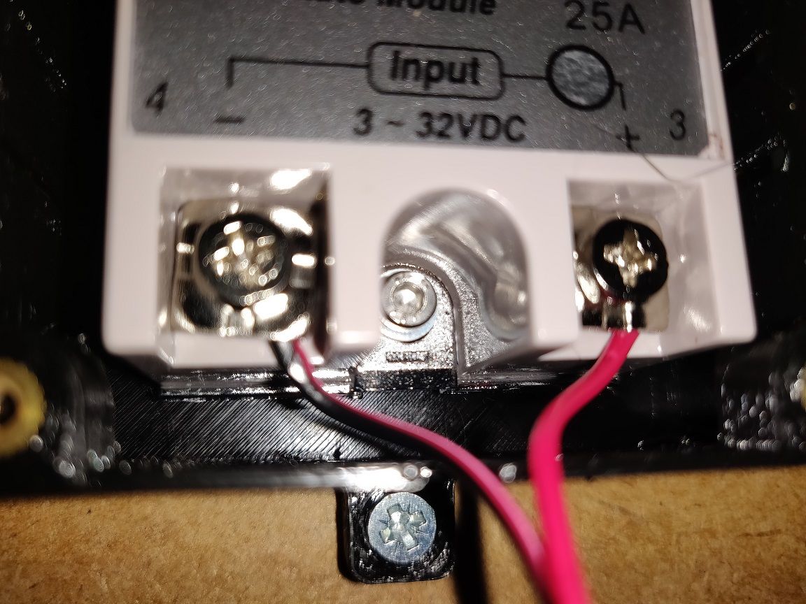
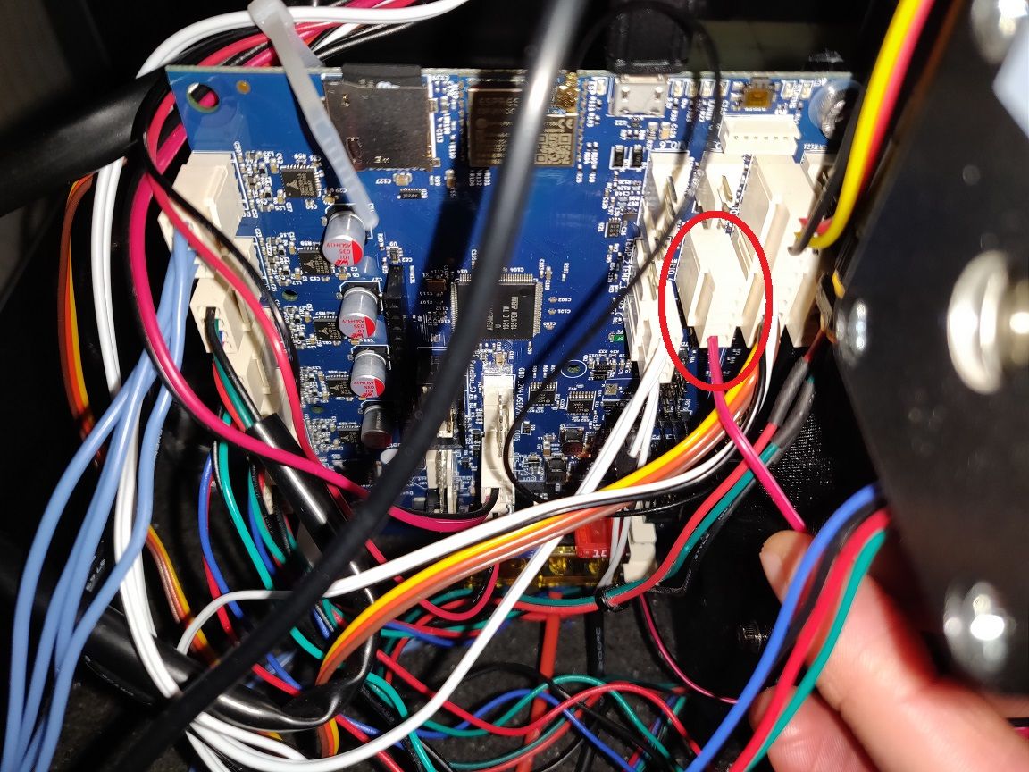
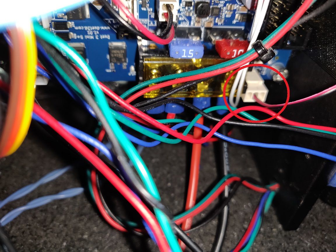
Is activating the relay using a GPIO pin an option? If so, how would I do that?
-
RE: Duet 3 Mini 5+ controlling Power Supply with SSRposted in Duet Hardware and wiring
@DIY-O-Sphere I added M80 to the end of the config file and applied the new configuration by running it but it did not activate the relay.
-
RE: Duet 3 Mini 5+ controlling Power Supply with SSRposted in Duet Hardware and wiring
From Machine-Specific General Tab:
Board: Duet 3 Mini 5+ (Mini5plus)
Firmware: RepRapFirmware for Duet 3 Mini 5+ 3.3RC2 (2021-05-11)
Duet WiFi Server Version: 1.26 -
RE: Duet 3 Mini 5+ controlling Power Supply with SSRposted in Duet Hardware and wiring
@dc42 Thanks. I could not get the SSR module working and due to the likelihood of future failures I have installed the SSR25DA but this is also not working.
I have M81 C"!pson" in my config.g file. I tried initially with i04.out and now have the positive input of the SSR25DA connected to 5V_EXT of IO_4 and the negative input of the SSR connected to pson. I have tried sending these commands: M80 C"!pson", M80 C"pson", M81 C"!pson", M81 C"pson, but the relay is not turning on the 12V PSU. My Duet Mini 5+ is being powered via the Micro USB using a 5V 2.5A power supply.
Am I doing something wrong or is there something I can try to troubleshoot this issue?
-
RE: Duet 3 Mini 5+ controlling Power Supply with SSRposted in Duet Hardware and wiring
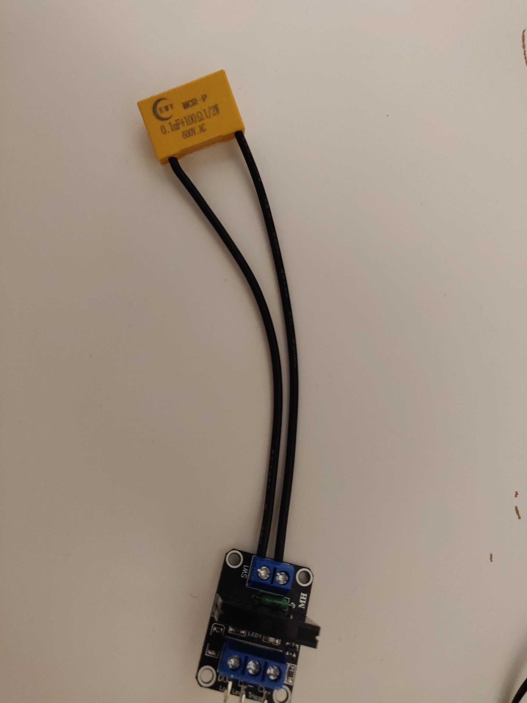
@dc42 Thanks. Is it also recommended to use a snubber like so between the two live wire contacts? In the past, I had to replace the SSR every 9 months or so which I'm guessing were failing due to voltage spikes.
-
RE: Duet 3 Mini 5+ controlling Power Supply with SSRposted in Duet Hardware and wiring
@dc42
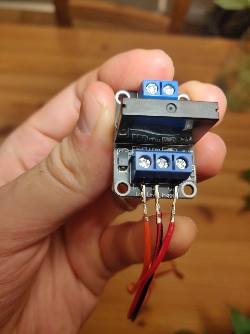
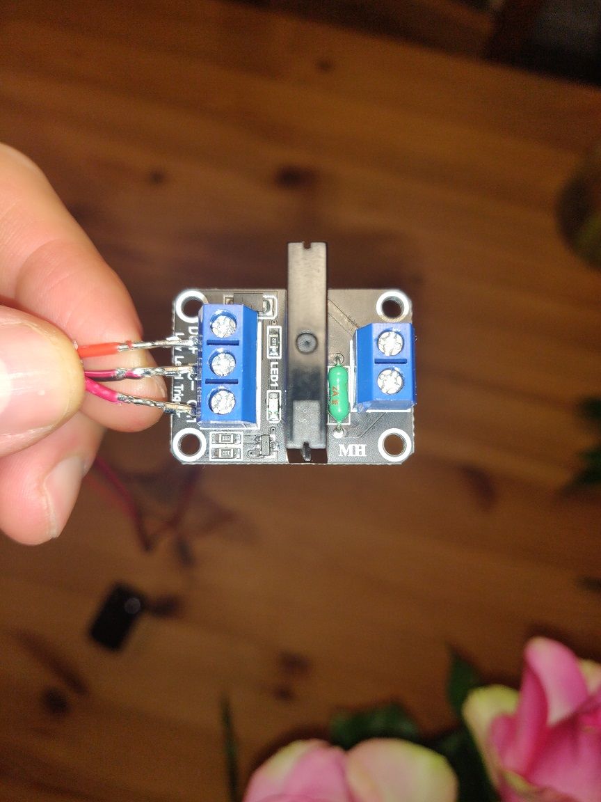
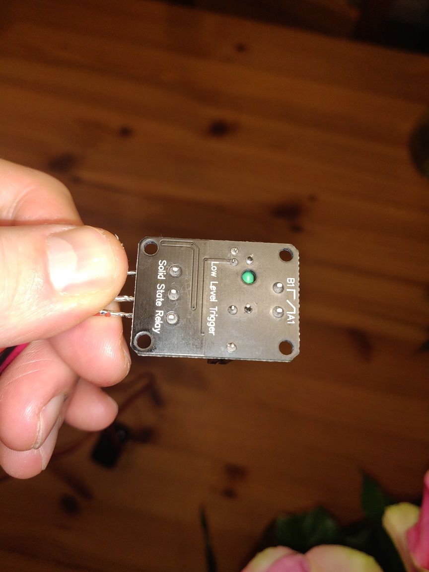 Thanks again for your patience and help.
 -
RE: Duet 3 Mini 5+ controlling Power Supply with SSRposted in Duet Hardware and wiring
This is the ciruit with the transistor I used previously with the transistor, diode and resistor that can be seen in the previous photo:
https://www.susa.net/wordpress/2012/06/raspberry-pi-relay-using-gpio/
Here are the labels of the board:
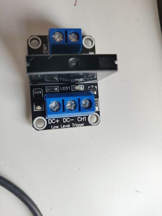
I guess I can directly connect 5V to DC+, PSON to DC- and 3.3V to CH1?
Then when I use M80 and M81, I expect it will turn the relay on and off.
-
RE: Duet 3 Mini 5+ controlling Power Supply with SSRposted in Duet Hardware and wiring
@dc42 it's an G3MB-202P 1565E, 5VDC Input Relay. Here's a datasheet of the relay https://components101.com/sites/default/files/component_datasheet/G3MB-202P-Datasheet.pdf and can't find a schematic for the board itself but it is this one: http://wiki.sunfounder.cc/index.php?title=1_Channel_5V_Solid_State_Relay_Module
-
Duet 3 Mini 5+ controlling Power Supply with SSRposted in Duet Hardware and wiring
Recently changed my set-up from RAMPS 1.4 with Octoprint to Duet 3 Mini 5 + and trying to turn my power supply on and off using the PSON pin (in my case, io4.out) with a solid state relay.
This set-up worked fine with my raspberry pi but I can't seem to get the relay to switch on and off using the Duet. I think it is a wiring issue as I have added the Power ON/OFF to the web GUI and tried M80 and M81 commands. I've tried using IO_4 5V_EXT, io4.out and GND but that didn't work. The set-up already includes a flyback diode which was present when it worked with my raspberry pi.
The solid state relay takes +, - and a trigger input pin.
Which pins should I be connecting these three pins to on the Duet 3 Mini 5 +?
