Using M581 external triggers to make control panel issues
-
Basically, I am attempting to replicate this but with the temp daughter board pins and newer 3.1.1 firmware: Using M581 - External Triggers and Building a Control Panel
I currently have two printers (a coreXY and a Ender3) both running a Duet Ethernet on 3.1.1 firmware and for most of the time I monitor them through DWC and webcams. However, for the first layer I make it a point to stand by the printers and control them with my phone's browser, which isn't too difficult when I only run one printer. Lately, I have been using both printers which makes controlling them from my phone very cumbersome. So I am attempting to create a small button panel with E-STOP, pause, babystep(+) and babystep(-) for each printer.
Since the coreXY is my test mule and have future plans on making it into an IDEX, I am attempting to use the temperature daughter board pins 3)CS1, 1)CS2, 7)CS3, 9)CS4 and 2)GND for my external triggers. Using momentary switches SPST-NO with a common ground attached to 2)GND pin.
Can I use 2)GND for my common ground for all the buttons? Are there better pins to use on the Duet Ethernet other than pins 3)CS1, 1)CS2, 7)CS3, 9)CS4 on the temp daughter board and the expansion pins?
My issue is that when a button is pressed it, it basically does an infinite loop of that button's macro until I press the mains switch. Once powered back on, the printer functions as normal until the external button is pressed again.
Once I can fix the infinite loop, Pause and baby stepping button's M581 will have R1 instead of R0.
Config.g
; Configuration file for Duet WiFi (firmware version 3.1.1)
; executed by the firmware on start-up
;
; General preferences
G90                                                ; send absolute coordinates...
M83                                                ; ...but relative extruder moves
M550 P"My CoreXY"                                 ; set printer name
M669 K1                                            ; select CoreXY mode

; Network
M552 P0.0.0.0 S1                                   ; enable network and acquire dynamic address via DHCP
M586 P0 S1                                         ; enable HTTP
M586 P1 S0                                         ; disable FTP
M586 P2 S0                                         ; disable Telnet

; Drives
M569 P0 S1                                         ; physical drive 0 goes forwards
M569 P1 S1                                         ; physical drive 1 goes forwards
M569 P2 S0                                         ; physical drive 2 goes backwards (Z1)
M569 P3 S1                                         ; physical drive 3 goes backwards (extruder)
M569 P4 S0					 					   ; physical drive 4 goes backwards (Z2)
M584 X0 Y1 Z2:4 E3 U4 P3                           ; set drive mapping
M671 X15:305:160 Y15:15:320 P0.5				   ; bed screw locations
M350 X16 Y16 Z16:16 E16 U16 I1                         ; configure microstepping with interpolation
M92 X160.00 Y160.00 Z1600.00:1600.00 U1600.00 E419.00  ; set steps per mm
M566 X1020.00 Y720.00 Z20 U20 E1000.00 P1         	   ; set maximum instantaneous speed changes (mm/min)
M203 X12000.00 Y9600.00 Z240:240 U240.00 E3600.00      ; set maximum speeds (mm/min)
M201 X1500.00 Y1000.00 Z50.00:50.00 U50.00 E2500.00    ; set accelerations (mm/s^2)
M906 X1400 Y1400 Z1100:1100 E1200 U1100 I30            ; set motor currents (mA) and motor idle factor in per cent
M84 S30                                                ; Set idle timeout

; Axis Limits
M208 X0 Y0 Z0 U0 S1                                ; set axis minima
M208 X330 Y315 Z380 U380 S0                        ; set axis maxima

; Endstops
M574 X1 S1 P"!xstop"                                ; configure active-low endstop for low end on X via pin xstop
M574 Y1 S1 P"!ystop"                                ; configure active-low endstop for low end on Y via pin ystop
M574 Z1 S1 P"!zstop+!e1stop" 						; configure active-low endstops for low end on Z via pins zstop and e1stop

; Z-Probe
M558 P0 H4.30 F120 T6000							; manual bed leveling
M557 X15:305:160 Y15:15:320                         ; define mesh grid with G29 for probing

;; ABL inductance sensor
;M558 P5 C"!zprobe.in+zprobe.mod" I1 H5 F120 T6000 A5 R1 S0.10 B0      ; set Z probe type to unmodulated and the dive height + speeds
;G31 P500 X-47 Y-20 Z0.815                          ; set Z probe trigger value, offset and trigger height
;M557 X0:280 Y25:295 P10                            ; define mesh grid

; Heaters
M308 S0 P"bedtemp" Y"thermistor" A"bed" T100000 B3950 R4700    		; configure sensor 0 as thermistor on pin bedtemp
M950 H0 C"bedheat" T0                              ; create bed heater output on bedheat and map it to sensor 0
M140 H0                                            ; map heated bed to heater 0
M143 H0 S105                                       ; set temperature limit for heater 0 to 105C
M307 H0 A89.2 C656.9 D1.7 V24.0 B0 S1.00           ; bed heater and set PWM limit

M308 S1 P"e0temp" Y"thermistor" A"hot end" T100000 B3950 R4700		; configure sensor 1 as thermistor on pin e0temp
M950 H1 C"e0heat" T1 Q100                          ; create nozzle heater output on e0heat and map it to sensor 1
M143 H1 S250                                       ; set temperature limit for heater 1 to 250C
M307 H1 A500.4 C279.3 D5.9 V24.1 S0.5 B0           ; hot end heater and set PWM limit

M308 S2 P"e1temp" Y"thermistor" A"chamber" T100000 B4725 C0.0000000706; configure chamber temp thermister on pin e1temp
M950 H2 C"e1heat" T2 								; chamber heater to heater 2
M141 H2;											; chamber heater called

; Fans
M950 F0 C"fan0" Q22500                             ; create fan 1 on pin fan1 and set its frequency
M106 P0 C"PartsFAN" S0 H-1 B0.2	R1	      	       ; set fan 0 value. Thermostatic control is turned off
M950 F1 C"fan1" Q500                               ; create fan 0 on pin fan0 and set its frequency
M106 P1 C"HotendFAN" S1 H1 T45 R1                  ; set fan 1 value. Thermostatic control is turned on

; Tools
M563 P1 S"hotend" D0 H1 F0                         ; define tool 1
G10 P1 X0 Y0 Z0                                    ; set tool 1 axis offsets
G10 P1 R0 S0                                       ; set initial tool 1 active and standby temperatures to 0C

; Triggers
M950 J1 C"spi.cs1"								; create pin1 for baby step (+)
M581 T2 P1 S1 R0								; create trigger for pin1
;M950 J2 C"spi.cs2"								; create pin2 for baby step (-)
;M581 T3 P2 S1 R0								; create trigger for pin2
;M950 J3 C"spi.cs3"								; create pin3 for emergency stop
;M581 T4 P3 S1 R0								; create stop trigger for pin3
;M950 J4 C"spi.cs4"								; create pin3 for emergency stop
;M581 T5 P4 S1 R0								; create stop trigger for pin4

; Custom settings
M912 S-8										   ; set electronics temperature monitor adjustment
M911 S10 R11 P"M913 X0 Y0 G91 M83 G1 Z3 E-5 F1000" ; set voltage thresholds and actions to run on power loss
M591 C"e0stop" D0 P1 S1                        	   ; Enable E1 Endstop for filament run out detection
M593 F38.25										   ; Configure Dynamic Acceleration Adjustment
M564 H0						  					   ; allow axis movement before homing
;;M572 D0 S0.50									   ; pressure advance

; Miscellaneous
T0                                                 ; select first tool
trigger2.g
; trigger2.g
; baby stepping (+)

M290 R1 S0.01			; increase baby step by 0.01mm
trigger3.g
; trigger3.g ; baby stepping (-) M290 R1 S-0.01 ; increase baby step by 0.01mm -
Hi,
I would try some other inputs just to see if your current choices are the cause.
Frederick
-
Tried different pins, tried inverting the pins, tried enabled pullup resistor, tried psu dc(-) for ground instead of a ground pin on the board and same result. As soon as I push the button, the bed just keeps moving. Removing the switch and just touching the wires together invokes the same continuous move.
M290 R1 S0.01When I type this into the console it only moves the bed once at 0.01mm. I would like to mimic this behavior with an external button. I just feel like I am missing something.
I just want the bed to move 0.01mm per button press. Ideally, it shouldn't matter if I hold the button for 0.100 seconds or for 10 seconds, it should only move the bed 0.01mm.
-
Maybe try adding a brief pause after the baby step command? G4 S1 for 1 second?
-
Could it be that the SPI pins you're using are being used for something else as well?
Any data traffic on that pin might execute the trigger.
I guess you could free the pin first but I don't know what RRF is using those pins for. -
@Phaedrux said in Using M581 external triggers to make control panel issues:
Maybe try adding a brief pause after the baby step command? G4 S1 for 1 second?
That seems to slow down the infinite loop with 1 second pauses in-between each baby step
@OwenD said in Using M581 external triggers to make control panel issues:
Could it be that the SPI pins you're using are being used for something else as well?
Any data traffic on that pin might execute the trigger.
I guess you could free the pin first but I don't know what RRF is using those pins for.I tried changing the pins in config.g
; Triggers
M950 J1 C"^exp.e2stop"			; create pin1 for baby step (+)
M581 T2 P1 S0 R0			; create trigger for pin1
;M950 J2 C"^exp.e3stop"			; create pin2 for baby step (-)
;M581 T3 P2 S1 R0			; create trigger for pin2
;M950 J3 C"^exp.e4stop"			; create pin3 for emergency stop
;M581 T0 P3 S1 R0			; create stop trigger for pin3
;M950 J4 C"^exp.e5stop"			; create pin4 for pause
;M581 T1 P4 S1 R0			; create stop trigger for pin4
for testing I am only uncommenting pin1 until I can get baby stepping(+) working.
Interesting thing happened while testing just pin1, the baby step button on DWC acts the same way as using trigger2.g.
So if trigger2.g has a G4 S1, the DWC button will mimic that with a one second pause while continuing an infinite loop. When I comment out the M950 and M581 for pin1, the baby step buttons on DWC act normal.
-
@jfitc004 said in Using M581 external triggers to make control panel issues:
M950 J1 C"spi.cs1"
M581 T2 P1 S1 R0-
Your switches pull the pin to ground, so you need to either invert the pin in the M950 command, or trigger on a low signal level (S0) instead of a high level (S1).
-
Enable the pullup resistor in the M950 command.
-
You may wish to add a G4 delay command in the macro file after the M291 command, to avoid contact bounce generating multiple triggers.
Duet WiFi hardware designer and firmware engineer
Please do not ask me for Duet support via PM or email, use the forum
http://www.escher3d.com, https://miscsolutions.wordpress.com -
-
@dc42 that definitely makes sense
so I should either have in my config.g
M950 J1 C"^spi.cs1"
M581 T2 P1 S0 R0
or
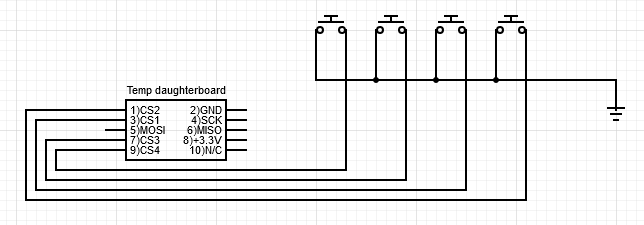
M950 J1 C"!^spi.cs1"
M581 T2 P1 S1 R0
and would either of these wiring diagrams work?
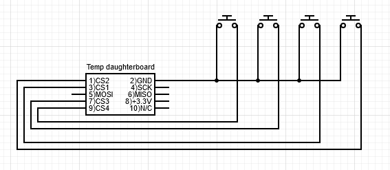
or
-
Yes. Best to use the ground on the daughter board for the switches, because the daughter board CS pins have no input protection apart from what's built into the MCU.
Duet WiFi hardware designer and firmware engineer
Please do not ask me for Duet support via PM or email, use the forum
http://www.escher3d.com, https://miscsolutions.wordpress.com -
@dc42 I think there might be something else going on. I wired it how you suggested and if I press my external switch, the babystep icon in DWC 'Status' or homeall in DWC 'Dashboard', the printer goes into a continuous loop of +0.01mm every 1 second until I restart using emergency stop. If I comment out M950 and M581 for external triggers the printer functions as expected.
trigger2.g
; trigger2.g
; baby stepping (+)

M400            ; wait for current move to finish
M290 R1 S0.01	; increase baby step by 0.01mm
G4 S1           ; one second pause
and here's my homeall.g
; homeall.g
; called to home all axes
;

G91                     ; relative positioning
G1 H2 Z5 F6000          ; lift Z relative to current position
M400			; Wait for current moves to finish
M913 X50 Y50 Z50	; Set motor percentage 50% of normal current
G1 H1 X-335 Y-335 F3000 ; move quickly to X or Y endstop and stop there (first pass)
G1 H1 X-335             ; home X axis
G1 H1 Y-335             ; home Y axis
G1 X5 Y5 F600           ; go back a few mm
G1 H1 X-335 F360        ; move slowly to X axis endstop once more (second pass)
G1 H1 Y-335             ; then move slowly to Y axis endstop
G1 H1 Z-380 F720 	; home Z axis
G1 Z5 F360 		; go back a few mm
G1 H1 Z-380 F360	; rehome Z axis at slower speed
G90			; absolute positioning
M400			; Wait for current moves to finish
M913 X100 Y100 Z100	; Set motor percentage to 100% normal current
Is there anything that looks suspect?
-
Upon further tinkering, it seems as though the for cs1, cs2, cs3 and cs4 pins for the temp daughterboard did not change behavior with NO-SPST switches for me. By using a spare makerbot mechanical endstop v1.2, I was able to get the desired behavior for trigger2.
I connected:
endstop 3.3v -----> to daughterboard 3.3v
endstop GND ----> to daughterboard GND
endstop output--> to daughterboard CS1and got the ideal expected results that I wanted.
Whether I used a '!' or not in M950 or 'S1' or 'S0' in M581 didn't make a difference in the intended behavior. Using the makerbot mechanical endstops is a temporary solution. If I want to use pins cs1-4 long term for my triggers without the current switches, I'll need to get some NC-SPST momentary switches.
So I am curious does my board have an issue if I cannot control the pin inversion or hi/lo signal with the firmware to have external triggers function with normally open switches?
-
I suspect that you forgot to enable the pullup resistors when you declared those SPI CS pins as inputs.
Duet WiFi hardware designer and firmware engineer
Please do not ask me for Duet support via PM or email, use the forum
http://www.escher3d.com, https://miscsolutions.wordpress.com -
@dc42 I am not sure what you mean. Is it not just simply adding a caret symbol at the beginning of the quoted C parameter in M950?
I was getting no change in behavior with these four different implementations with a SPST-NO switch.
M950 J1 C"^spi.cs1"
M581 T2 P1 S0 R0
M950 J1 C"!^spi.cs1" M581 T2 P1 S1 R0M950 J1 C"^spi.cs1" M581 T2 P1 S1 R0M950 J1 C"!^spi.cs1" M581 T2 P1 S0 R0The button press would invoke trigger2.g and would run it continuously until I held the button down or by attaching the pin to ground. So I would assume that inverting the pin or changing the trigger level from high to low or vice versa would fix that behavior but it didn't.
I am by no means an expert or pretend to be with gcode, I am just worried I did something to the board if it can't be solved with code.
Do I need to power off the board for the pullup resistors to function or is the restart after saving the config.g suffice?
Is it possible to use a multimeter to check high state or low state of the resistor? I am guessing its probably of the 4.7kΩ variety
-
@jfitc004 said in Using M581 external triggers to make control panel issues:
Do I need to power off the board for the pullup resistors to function or is the restart after saving the config.g suffice?
Re-running config.g or resetting should be enough.