@peter247 I cheated !
I soldered my mosfet on it, I wasn't able to melt the negative pad but I could surface solder it.
Right now I'm running my bed PID, everything seems in order.
Thanks a million time to both of you
@Phaedrux
@peter247 I cheated !
I soldered my mosfet on it, I wasn't able to melt the negative pad but I could surface solder it.
Right now I'm running my bed PID, everything seems in order.
Thanks a million time to both of you
@Phaedrux
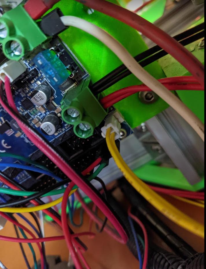
@peter247 thanks for the idea ! I have two mosfets laying around my workshop. I'll do that for sure, it will protect the new terminal !
@phaedrux Okay thank you so much for the heads-up, my soldering iron is definitely not up to par so I will look for an other one.
I will update here once the terminal has been changed. I hope I'll be able to find an equivalent terminal locally
Thanks once again for all of your help, I really appreciate it
@phaedrux Okay, I was waiting to see if there was any way to have it RMA under warranty before touching it and potentially voiding the warranty if I had one.
I will see if I can find the terminal locally and will solder it back together.
I think it will work because with no wire inside the terminal I could see 12v. I guess tightening the terminal on the wires flexed it just enough so the burnt leg wouldn't contact with the trace anymore.
Thank you so much for your help, I appreciate it
@phaedrux Hello
This is a stock Anet A8 bed.
The Stock heated bed is 12V 1.2Ohm i.e. 10 Amp Peak Current.
When I measure it, I get 1.1ohm so the bed is not shorted or anything.
Also it is very weird that no fuse blew up when the terminal toasted. It feels like an early failure of the terminal
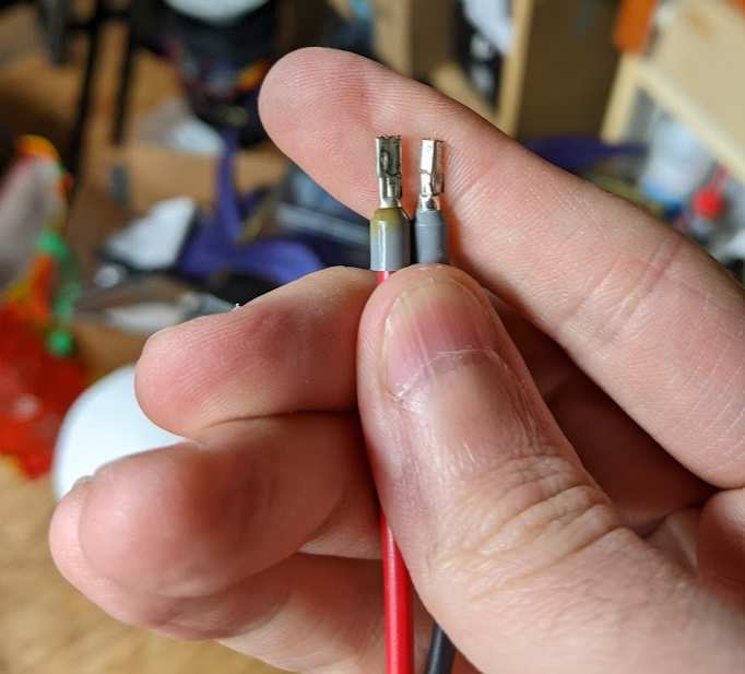
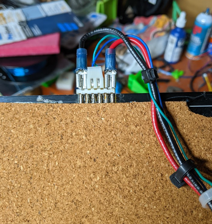
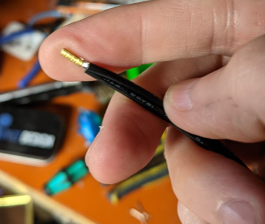
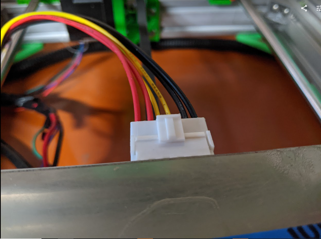
I used ferrules, see my heatbed wiring (keep in mind what you saw before was a brand new heatbed I just received)
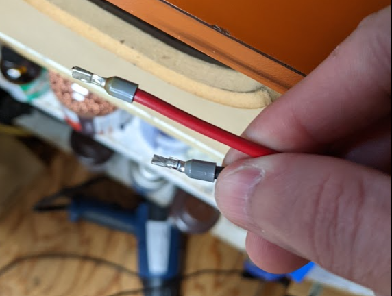
Wire is there two wires, I have no idea, that how the bed came to me. My guess is that they tried to save money using smaller gauge wires but two of each. My old bed wasn't like that. I can provide picture of it if required. Even the doubled wires have ferrules :
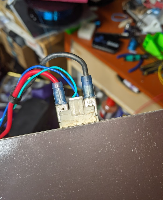
The inside of the terminal looks good in my opinion :
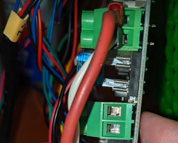
Unfortunately, I though it was just a reflection but now with the flash it's clearly discoloured :
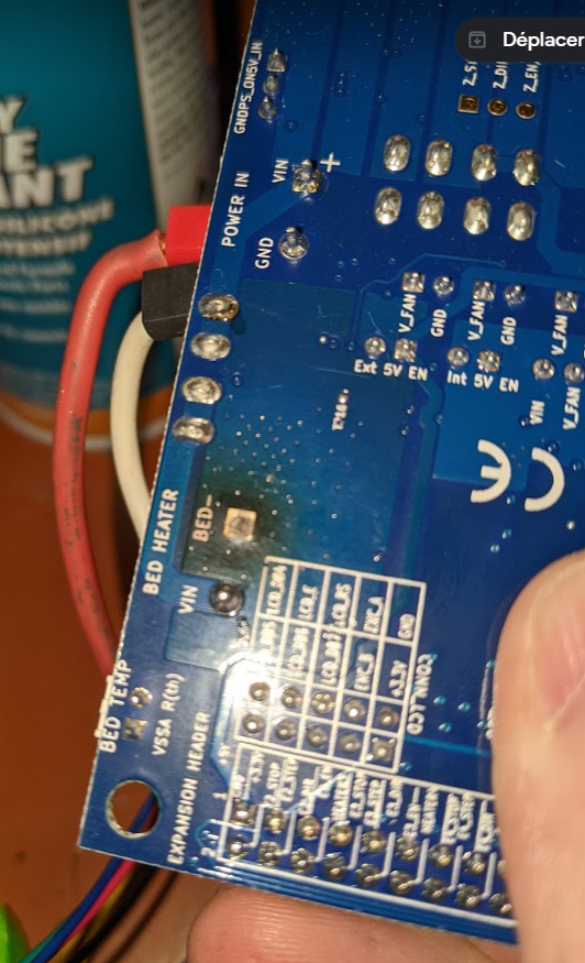
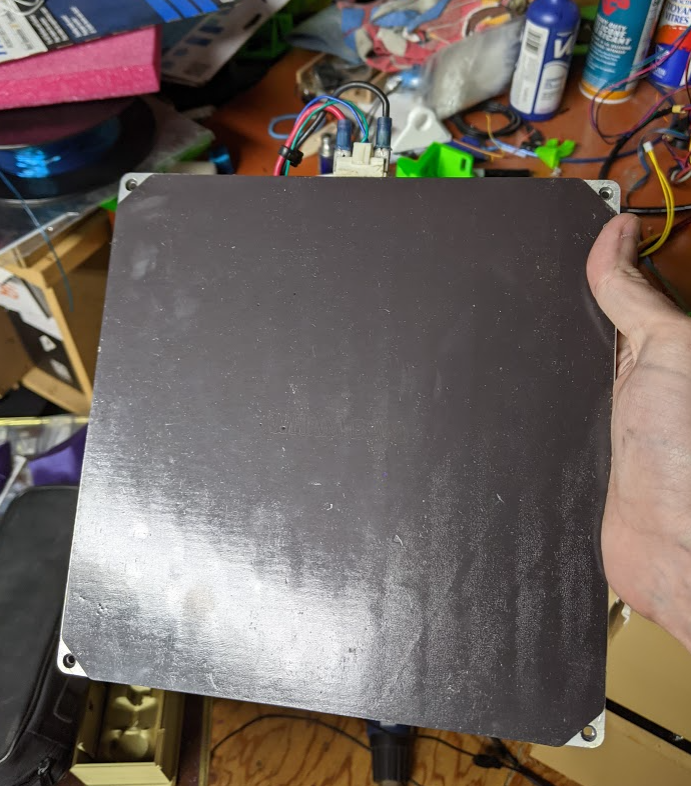
So I took the board out of the machine, and the negative lead crumbled to dust.
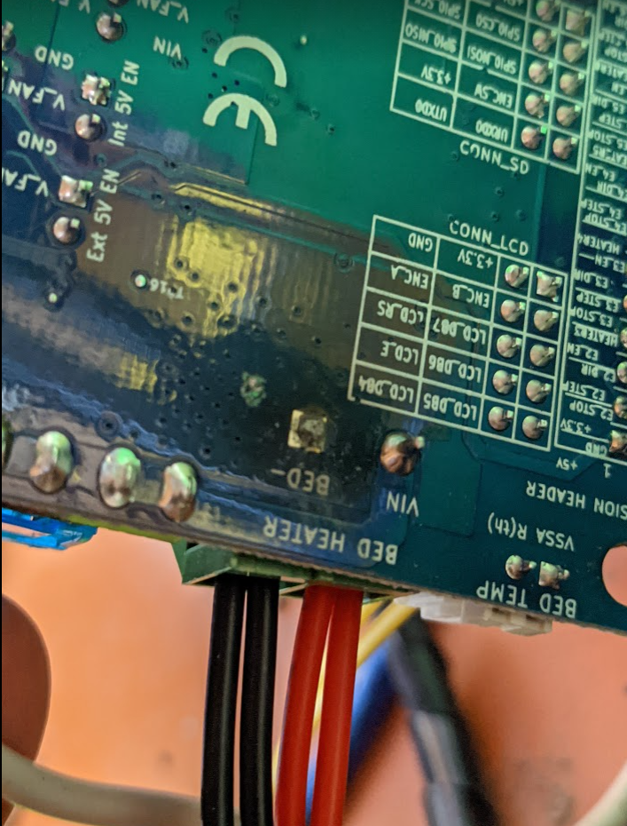
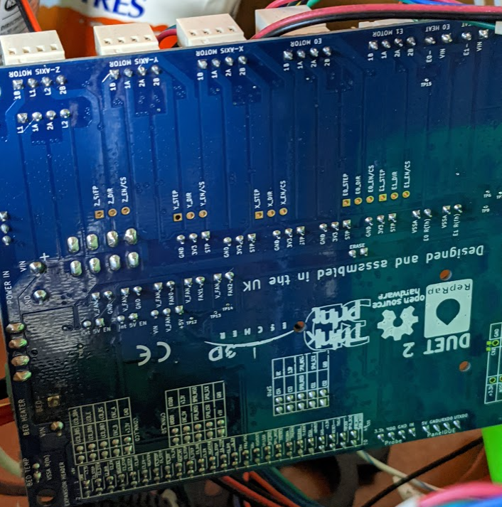
As far as I can see, it doesn't seem to have any damaged anywhere else.
Do you think it's something a soldering iron could fix or potentially the whole trace is burnt out ?
Thanks once again for your help, I appreciate it
@phaedrux Hello, thanks for the fast reply !
Here's the pictures. Talking about the terminal, I can't really see anything wrong with it, however it feels a little bit wiggly. It never occured to me to look behind the board to see if something is obvious
I will report back soon, when I remove the board
Hello all,
Something weird happened to me this week-end, I have a Duet 2 wifi
I was printing, when I came to check my print for the final hour, I realised the bed was 23 instead of 60. I found strange that the machine didn't stop but I could finish my print with no issue.
I used my multimeter and realised I had no 12v at the output for the bed. I immediately thought it was a fuse. I tested all of them and they're all good. On top of that, if I remove the fuse needed for the bed, the red light doesn't come on when I ask the printer to heat the bed.
I then changed my wiring and replaced my bed by a brand new one. I still have the same behavior.
As soon as I unconnect the bed, I have 12v on the bed output. When I plug the bed back, I end up with 0v
To me it feels like hardware failure but I hope I'm wrong.
Just in case you need it, here's my config, but I haven't touched anything since a while
; Heaters
M308 S0 P"bedtemp" Y"thermistor" T100000 B4725 C7.06e-8 ; configure sensor 0 as thermistor on pin bedtemp
M950 H0 C"bedheat" T0 ; create bed heater output on bedheat and map it to sensor 0
M307 H0 B0 S1.00 ; disable bang-bang mode for the bed heater and set PWM limit
M140 H0 ; map heated bed to heater 0
M143 H0 S130 ; set temperature limit for heater 0 to 130C
M308 S1 P"e0temp" Y"thermistor" T500000 B4723 C1.196220e-7 ; configure sensor 1 as thermistor on pin e0temp
M950 H1 C"e0heat" T1 ; create nozzle heater output on e0heat and map it to sensor 1
M307 H0 A93.5 C632.2 D1.6 V12.5 B0 S1.00 ; Bed PID
M307 H1 A350.4 C119.1 D3.7 V12.5 B0 S1.00 ; Heater PID
Thanks so much in advance
Yeah but it is so easy with the tutorial. I can't believe my multimeter was the main culprit ahahah
Last post !
Found out my issue was completely stupid. I had a bad multimeter that showed continuity in my servo wire when there was none, it was broken
Now it works !
Thanks a lot for everything
I measured the voltage going into the bltouch and it's 4.95v which I'm sure is okay. I'm really clueless now
No I didn't try to reallocate anything. And honestly since now my Z axis is working I'm scared to touch anything, I'm just super glad I got this part working. I really hope I can get my bltouch working now so I can finally enjoy my shiny new board
Note that I have a genuine BLtouch classic if it might help you troubleshoot my problem
Okay what I did is wire both of my motors to the same connector (ZA) and instead of 500mA I put 1000mA.
Now my Z axis is moving. The only thing left is the BLtouch.
Now that I can home Z, I realise that it doesn't use my BLtouch for the homing, I pull and push the pin manually and it doesn't stop.
Thanks in advance for all the help
Hello,
Thanks a lot for giving me a hand.
On the motors it is written :
Anet Step motor
42SHDC3025-24B
My deployprobe.g reads as such :
; deployprobe.g
; called to deploy a physical Z probe
;
; generated by RepRapFirmware Configuration Tool v2.1.8 on Mon May 04 2020 13:12:37 GMT-0400 (Eastern Daylight Time)
M280 P3 S10 I1 ; deploy BLTouch
and my retractprobe.g :
; retractprobe.g
; called to retract a physical Z probe
;
; generated by RepRapFirmware Configuration Tool v2.1.8 on Mon May 04 2020 13:12:37 GMT-0400 (Eastern Daylight Time)
M280 P3 S90 I1 ; retract BLTouch
Thanks once again for the help, I really appreciate it
EDIT : I tried to wire only one Z motor and put the jumpers in ZB connector. I still have the same error, I tried with both motor
Hello all,
I'm totally new here, I just got a Duet 2 Wifi yesterday.
I was so excited to set that up.
However I have at the moment two issues.
The first is "Motor phase A and phase B may be disconnected reported by driver 2"
I checked my crimps, tugged on my wires. Everything looks okay. I tried to swap the wires but I keep having the same error so I put them how it was wired originally on the Anet A8. I read on here that people seemed to have the same issue with an older firmware or with low current motor.
I have a Duet 2 Wifi 1.02 or later
Firmware 2.05.1
Wifi server version 1.23
Web interface version 1.22.6
Second thing. I wired a bltouch as per the wiki. I did my config with the configurator. I can't deploy or retract the bltouch at all.
Same thing here, checked my crimps and double checked my connections and my config. It seems all good.
Here is my config.g if it can help :
; Configuration file for Duet WiFi (firmware version 2.03)
; executed by the firmware on start-up
;
; generated by RepRapFirmware Configuration Tool v2.1.8 on Mon May 04 2020 13:12:37 GMT-0400 (Eastern Daylight Time)
; General preferences
G90 ; send absolute coordinates...
M83 ; ...but relative extruder moves
M550 P"Metal Machine" ; set printer name
; Network
M552 S1 ; enable network
M586 P0 S1 ; enable HTTP
M586 P1 S0 ; disable FTP
M586 P2 S0 ; disable Telnet
; Drives
M569 P0 S0 ; physical drive 0 goes forwards
M569 P1 S0 ; physical drive 1 goes forwards
M569 P2 S1 ; physical drive 2 goes backwards
M569 P3 S0 ; physical drive 3 goes forwards
M584 X0 Y1 Z2 E3 ; set drive mapping
M350 X16 Y16 Z16 E16 I1 ; configure microstepping with interpolation
M92 X100.00 Y100.00 Z400.00 E415.00 ; set steps per mm
M566 X600.00 Y600.00 Z18.00 E300.00 ; set maximum instantaneous speed changes (mm/min)
M203 X6000.00 Y6000.00 Z180.00 E6000.00 ; set maximum speeds (mm/min)
M201 X1500.00 Y1500.00 Z100.00 E10000.00 ; set accelerations (mm/s^2)
M906 X500 Y500 Z500 E800 I30 ; set motor currents (mA) and motor idle factor in per cent
M84 S30 ; Set idle timeout
; Axis Limits
M208 X-33 Y-10 Z0 S1 ; set axis minima
M208 X220 Y220 Z240 S0 ; set axis maxima
; Endstops
M574 X1 Y1 S0 ; set active low and disabled endstops
M574 Z1 S2 ; set endstops controlled by probe
; Z-Probe
M307 H3 A-1 C-1 D-1 ; disable heater on PWM channel for BLTouch
M558 P9 H5 F120 T6000 ; set Z probe type to bltouch and the dive height + speeds
G31 P500 X0 Y-38 Z2.36 ; set Z probe trigger value, offset and trigger height
M557 X20:200 Y20:200 S40 ; define mesh grid
; Heaters
M307 H0 B0 S1.00 ; disable bang-bang mode for the bed heater and set PWM limit
M305 P0 T100000 B4725 C7.060000e-8 R4700 ; set thermistor + ADC parameters for heater 0
M143 H0 S130 ; set temperature limit for heater 0 to 130C
M305 P1 T100000 B4725 C7.060000e-8 R4700 ; set thermistor + ADC parameters for heater 1
M143 H1 S400 ; set temperature limit for heater 1 to 400C
; Fans
M106 P0 S0 I0 F500 H-1 ; set fan 0 value, PWM signal inversion and frequency. Thermostatic control is turned off
M106 P1 S1 I0 F500 H1 T45 ; set fan 1 value, PWM signal inversion and frequency. Thermostatic control is turned on
; Tools
M563 P0 D0 H1 F0 ; define tool 0
G10 P0 X0 Y0 Z0 ; set tool 0 axis offsets
G10 P0 R0 S0 ; set initial tool 0 active and standby temperatures to 0C
; Custom settings are not defined
; Miscellaneous
T0 ; select first tool
Thank you so much in advance, and I hope to be soon good enough to be able to provide help to others around here.