@dc42 Understandable. Thank you for your assistance, I have ordered that resistor and will try to replace it.
Posts made by KarlMarklund
-
RE: Toolboard temp sensor resistanceposted in Duet Hardware and wiring
-
RE: Toolboard temp sensor resistanceposted in Duet Hardware and wiring
@dc42 I have scraped a bit to remove any oxidation, but I dont think my multimeter is that accurate (given the result I get for R22).
R21 - 128K
R22 - 1,88Kas ref:
R24 - 9,47K
R32 - 1,87K
R23 - 9,5Would this be a similar resistor to what it should be as a replacement?
https://www.digikey.se/product-detail/en/panasonic-electronic-components/ERA-2AEB222X/P2-2KDCCT-ND/1706191 -
RE: Toolboard temp sensor resistanceposted in Duet Hardware and wiring
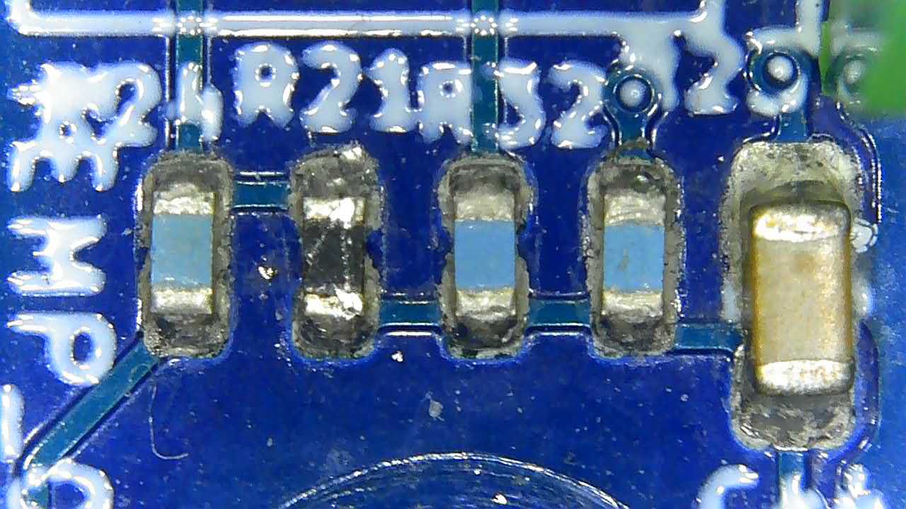
@dc42 it doesnt look healthy, see picture.
Not sure if it should have the same color as the others, or if it is supposed to be black.
-
RE: Toolboard temp sensor resistanceposted in Duet Hardware and wiring
@dc42 Hi again, have had much to do so havent had time to check this yet.
Checking it now though and get a reading of about 127K, so it will have to be replaced.While I am at it, should i replace R32 as well, with the same spec resistor? Looks like it is connected to the ADVREF Monitoring.
-
RE: Toolboard temp sensor resistanceposted in Duet Hardware and wiring
@T3P3Tony Thank you, I will check it
-
RE: Toolboard temp sensor resistanceposted in Duet Hardware and wiring
If I do M308 S1 it says last error: short-circuit in sensor. I cant find where that short-circuit would be..
But that would explain why i get 0 degreees instead of 2000 (open-circuit).
Connecting it with a separat cable to main board it gives me correct reading.
Since i might have fried the sensor somehow is it possible to run sensor from MB but still use toolboard for out0?
Not sure if i have missed some settings but if I do that, I get the temperatur but as soon as I activate the tool it shows status fault. -
Toolboard temp sensor resistanceposted in Duet Hardware and wiring
Hello!
Does anyone know what the resistance should be between the pins on TEMP_0 and TEMP_1?I have been getting issues with the PT1000 readings, now it shows a temperature of 0, and of course faults as soon as I turn on the heater.
Yes, I am the one who replaced the connectors on my board with JST ones. Though i cant see any issues with the soldering, and all the other connectors (fans) work as they should.
The readings I get between the pins:
VSSA-T0: 103k
VSSA-T1: 3kI think the T0 has a different ADC so that might be what is increasing.
I have currently ran cables from the mainboard, which is not optimal but works

Thanks in advance! -
RE: My thoughts on Toolboard 1LCposted in Duet Hardware and wiring
Thank you all for your comments!
@dc42 I do think that screws are easier for some, but as mentioned these are generally difficult to determin the correct torque, thus I have had a lot of those suddenly strip the threads.
Even as a hobbyist I do find it more convenient with connectors. There is some more work to do upfront (with crimping the connectors) it is easier to make connectors with the correct order (dont want to deal with reverse polarity or not getting a reading because wire 2 happened to land in port 3).Those screw terminals also have no physical connection to the board except for the terminal connectors, meaning that the torque from screwing have the risk of twisting them.
As @deckingman said, one option could be to have a barebones board, though I dont think that is the Duet3D way, as the other boards come with connectors installed.
-
My thoughts on Toolboard 1LCposted in Duet Hardware and wiring
Hello all,
new to the forum, but have been using Duet for a couple of years now.I thought I would share my thoughts on the Toolboard, and have compiled them in this video.
https://www.youtube.com/watch?v=6X_vZnJmBYYLove the concept but think the board could be improved.
Take care!