@Phaedrux
So...during my troubleshooting mid 2022, I must have yanked the USB cable causing the USB connector on the board to rip off the board (taking many of the pads with it).
I found this other thread and was able to successfully solder on a USB cable to the ends of the resistors. (At least I was able to communicate with it in the past)
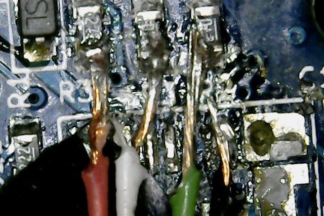
I will take a look to make sure there are no electrical issues with the solder joints (e.g. the exposed wires are touching something else...the flux from the poor solder job ate through something?!!). The cable itself seems fine (at least based on a simple continuity test on the four wires to the USB connector).
So far, I can get a resistor measurement across the "green" resistor of ~27 OHMs, but I can't seem to get a reading across the "red" or "white" resistors... That can't be good...
@dc42
Interesting. Thanks for the information.
-
"Excessive 5V power" - Would I need to get one of those USB power meters to verify this? (I don't have a working bench top power supply unfortunately...) - I measured across PIN1 and PIN 2 on the expansion connector and it was reading 4.76V...I am guessing this is not good either.
-
"Does [the main processor chip] get hot?" - Not that I can tell. Left it plugged in to the USB port for 10 mins and I feel like I can leave my finger on the chip indefinitely.
-
"3.3V supply to it is low" - I measured across the 3.3 and GND on the endstop connectors and they seem to be measuring 3.3V - 3.31 V so I am guessing it is not this either.
So if there is something wrong with my 5V USB connection...I assume if I used Vin to power the board + connect this board to my laptop to avoid ground loops, that should help right? Or not? (I mean it didn't work for me originally and that is why I took the board out of the 3D printer completely...but maybe?!?)
Thanks again for the support.
 )
)")