@dc42 here the files, yes the report is the same with M400 in between.
config.g
test_microstep.g
Posts made by leone
-
RE: [3.6.0-rc.2] Expansion boards microstep positioning errorposted in Beta Firmware
-
[3.6.0-rc.2] Expansion boards microstep positioning errorposted in Beta Firmware
Hi all,
before beta.4 there was a positioning error of about one microstep when movements stopped. I'm using now rc.2 but I think it is still an issue for drives connected to expansion boards.The test I've done is:
- steps/mm is 80 -> 0.0125 mm/microstep.
- X-axis motor connected to 1HCL. Y and Z are connected to MB6HC.
- home all
- Run test macro 3 times (no homing in between)
Test macro:
G1 X0 Y0 Z0
M118 S{"User Position "^move.axes[0].userPosition^",Y "^move.axes[1].userPosition^", Z "^move.axes[2].userPosition^"}
M118 S{"Machine Position "^move.axes[0].machinePosition^",Y "^move.axes[1].machinePosition^", Z "^move.axes[2].machinePosition^"}G1 X10 Y10 Z10 F600
M118 S{"User Position "^move.axes[0].userPosition^",Y "^move.axes[1].userPosition^", Z "^move.axes[2].userPosition^"}
M118 S{"Machine Position "^move.axes[0].machinePosition^",Y "^move.axes[1].machinePosition^", Z "^move.axes[2].machinePosition^"}What I get echoing the user and machine positions in between each move:
Run 1
User Position 0.00,Y 0.00, Z 0.00
Machine Position 0.00,Y 0.00, Z 0.00
User Position 9.988,Y 10.000, Z 10.000
Machine Position 9.988,Y 10.000, Z 10.000Run2
User Position 0.0125,Y 0.0125, Z 0.00
Machine Position 0.0125,Y 0.0125, Z 0.00
User Position 9.988,Y 9.988, Z 10.000
Machine Position 9.988,Y 9.988, Z 10.000Run3
User Position 0.0125,Y 0.00, Z 0.00
Machine Position 0.0125,Y 0.00, Z 0.00
User Position 9.988,Y 9.988, Z 10.000
Machine Position 9.988,Y 9.988, Z 10.000It's also very strange that from the second run also the Y axis (connected to MB6HC) seems to have a similar problem, while if I connect the X-motor to MB6HC all the returned positions are precise.
Can someone replicate this behaviour? Thanks in advance.
-
RE: Collect ADC sensor values at high frequencyposted in Firmware developers
@dc42 about 200-250Hz is good for what I'm doing now. If higher is possible, it is even better for future uses.
-
Collect ADC sensor values at high frequencyposted in Firmware developers
Hi all,
I'd like to ask your opinion about having the possibility to stream data at high frequency from a generic ADC sensor (connected to an expansion board) to a CSV file (similar to what the M956 is doing with the accelerometer). I have this need because the CAN frequency at which the sensors are updating is too low for some of the custom calibrations I'm doing. I have something working based on the AccelerometerHandle, but I'd like to see if it is of interest to do a proper refactor and open a pull request from that.
My idea would be to have something like: M956.1 Pbb.nn Snnn F"" (board.pin name, number of samples, filename). The implementation would be similar to how the accelerometer works, so:
- add two CAN messages, one for the start request and one for the data structure (or somehow use the accelerometer messages?)
- an AdcStreamHandler: to be initialized from the pin name and have a task to collect the raw data and build/send the CAN messages
- modify AveragingFilter.h to return all the collected samples (without interfering with the average)
Side question: I'm not quite sure at which frequency the ADC is updating the filter queue: from a comment "Readings will be taken and about every 'ticksPerCall' milliseconds the callback function will be called with the specified parameter and ADC reading.". It seems like the analog ports are configured with 1, does this mean the adcFilter queue is filling up at 1ms rate?
BTW, what do you think about this feature? The main goal is to get values at high frequency (buffered, not necessarily in real-time, but with a known time interval between the samples). Do you see other approaches that could be followed to have the same functionality?
Thank you in advance.
-
RE: [FW 3.5.2] High jerk good for circular path not for cornersposted in Tuning and tweaking
@Triet, what @gloomyandy correctly explained is how the jerk is implemented in RRF 3.5.x and also 3.6 betas. The jerk set from the configuration is the max allowable speed change that a specific axis can do between two consecutive moves: RRF checks the components of the direction vector between two consecutive moves to understand how much each axis has to change in speed, if this change is greater than the threshold (jerk), then the threshold itself will be used.
What I proposed as adaptive jerk meant to change dynamically this threshold, based on a non linear relationship with the direction angle. It's one layer of logic above what RRF is already doing, maybe something like "adaptive MAX jerk" would have been more clear
")
I actually paused this investigation because the results I got with the 3.6 betas and the new input shaping are very good and fixed most of my issues.
I can confirm that find a reliable logic to implement here is more difficult than it might seems. Maybe in future I'll give another chance to the junction deviation or the "adaptive MAX jerk" on top of 3.6 to see if there are real benefits. -
RE: [3.6.0-beta.2 and prev] Random out of syncposted in Beta Firmware
@dc42 yes, I logged that message right after the expansion boards got out of sync and the print shifted. I was also able to sniff the CAN messages of another print that failed in the same way and that's where I noticed 'lastTimeAcknowledgeDelay' being equal to zero for more than 10 times consecutively. That's how I started to test higher values for MaxTimeSyncDelay (initially 375), but I didn't know how far I could go.
-
RE: [3.6.0-beta.2 and prev] Random out of syncposted in Beta Firmware
@dc42 I still have one:
All averaging filters OK Never used RAM 164992, free system stack 172 words Tasks: Move(3,nWait 7,0.0%,126) TMC(2,delaying,1.4%,51) HEAT(2,nWait 6,0.1%,89) CanAsync(5,nWait 4,0.0%,66) CanRecv(3,nWait 1,0.1%,73) CanClock(5,nWait 1,0.0%,63) LED(2,delaying,0.0%,123) ACCEL(3,nWait 6,0.0%,87) MAIN(1,running,97.4%,319) IDLE(0,ready,0.0%,29) AIN(2,delaying,1.0%,259), total 100.0% Owned mutexes: Last reset 02:15:02 ago, cause: power up Last software reset data not available Moves scheduled 37920, hiccups 0 (0.00/0.00ms), segs 37, step errors 0 (types 0x0), maxLate 0 maxPrep 62, ebfmin 0.00 max 0.00 Peak sync jitter -3/41, peak Rx sync delay 187, resyncs 1/0, no timer interrupt scheduled, next step interrupt due in 4247606105 ticks, disabled VIN voltage: min 24.2, current 24.4, max 24.5 MCU temperature: min 51.7C, current 58.0C, max 60.5C Driver 0: pos 12510580, 2056.0 steps/mm, standstill, SG min 0, read errors 0, write errors 0, ifcnt 25, reads 53750, writes 25, timeouts 0, DMA errors 0, CC errors 0 Last sensors broadcast 0x3fe0000000 found 9 225 ticks ago, 0 ordering errs, loop time 0 CAN messages queued 192060, send timeouts 0, received 305253, lost 0, ignored 16, errs 0, boc 0, free buffers 22, min 22, error reg 0 dup 0, oos 0/0/0/0, bm 0, wbm 0, rxMotionDelay 299, adv 35157/37138 Accelerometer: ADXL345, status: 00 I2C bus errors 0, naks 0, contentions 0, other errors 0 -
RE: [3.6.0-beta.2 and prev] Random out of syncposted in Beta Firmware
@dc42 with CanClockIntervalMillis = 200 the number of high acknowledge delays depends on how many clashes with other transmissions we have, and since it seems to happen quite random, the comparison with CanClockIntervalMillis = 199 is difficult to do. I tried to analyse 10 minutes in idle state with different configurations of CanClockIntervalMillis and MaxTimeSyncDelay.
I think I will run some prints with CanClockIntervalMillis = 199 and MaxTimeSyncDelay = 500, to see if the resync issue still occurs. From the analysys below it seems to be the one with less number of zeros and less high delays.
Do you think this is something relevant to include in the next release?freq199_thr300
Percentage of zeros: 0.50%
Percentage of values between 1 and 10: 96.60%
Percentage of values between 11 and 100: 1.13%
Percentage of values between 101 and 200: 1.10%
Percentage of values greater than 200: 0.67%freq200_thr500
Percentage of zeros: 0.00%
Percentage of values between 1 and 10: 93.77%
Percentage of values between 11 and 100: 2.30%
Percentage of values between 101 and 200: 2.10%
Percentage of values greater than 200: 1.83%freq199_thr500
Percentage of zeros: 0.00%
Percentage of values between 1 and 10: 96.63%
Percentage of values between 11 and 100: 1.30%
Percentage of values between 101 and 200: 1.10%
Percentage of values greater than 200: 0.97%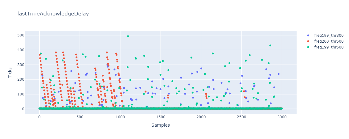
-
RE: [3.6.0-beta.2 and prev] Random out of syncposted in Beta Firmware
@dc42 thanks for the suggestion!
From M122, "peak Tx sync delay" is about 480 both when the machine is idle and when is printing. This might correspond to the 600us needed to send the CANFD packet, right?
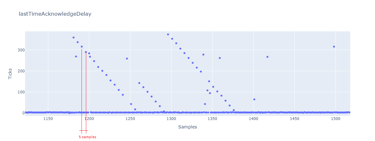
I tried with CanClockIntervalMillis = 199 and below is the (blue) plot from the CAN analyser. The interesting thing now is that the samples between ~4 and 300 are way more than before.
Then I also increased the MaxTimeSyncDelay to 500, and the number of zeros is considerably reduced, which I think is the goal to avoid resyncs.
Could this value of MaxTimeSyncDelay lead to other issues?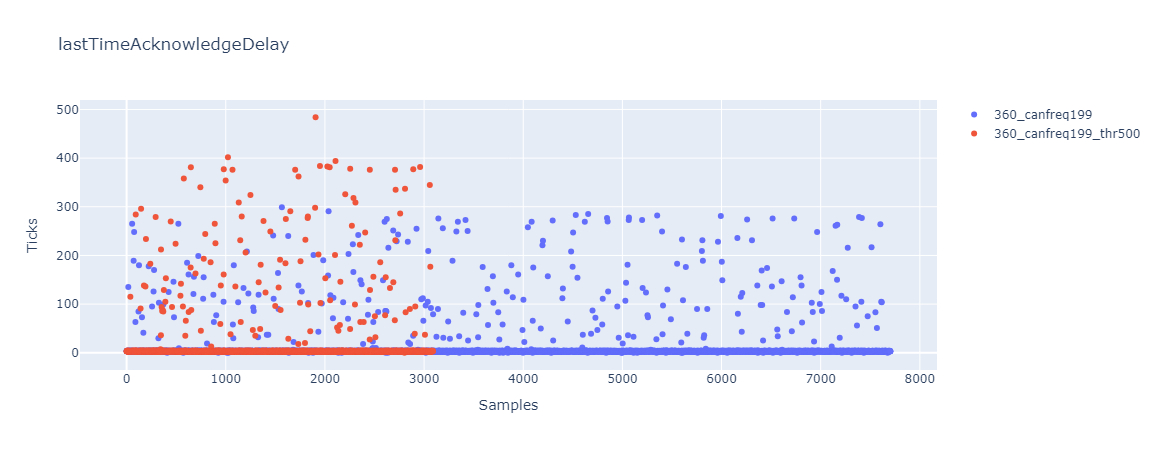
-
[3.6.0-beta.1] Step timing errorposted in Beta Firmware
Hi all,
I'm just reporting a step timing error I got with beta 1:2024-11-29 20:17:27 [warn] Error: Movement halted because a step timing error occurred (code 3). Please reset the controller. 2024-11-29 20:17:27 [warn] Error: Existing: start=159625402 length=7371, new: start=159630740, overlap=2033 time now=159629503 -
RE: [3.6.0-beta.2 and prev] Random out of syncposted in Beta Firmware
now I'm doing some tests increasing
StepTimer::MinSyncIntervalfrom 2000 to 4000. I noticed it was already increased some years ago, it might be the same issue, I am also running on a SAME70. -
RE: [3.6.0-beta.2 and prev] Random out of syncposted in Beta Firmware
Thanks @droftarts.
Update note: I got a resync also withMaxTimeSyncDelay = 375. -
[3.6.0-beta.2 and prev] Random out of syncposted in Beta Firmware
Hi all,
from 3.6.0-beta.1 I started to have some layer shifts in the first layers of a print. These shifts happen randomly (the same gcode might shift in one print and not in the consecutive one, or just in another position). Still, I didn't find a way to replicate exactly the issue. The shift happens because the expansion boards go out of sync for about 2 seconds and the movement commands are discarded (as intended behavior from 3.6.0-beta.1).
So far, it never shifted when the bed compensation was disabled or, when enabled, it never shifted above the tapering height (5mm).
To debug, I connected a can sniffer device and analyzed the TimeSync messages. The out-of-sync happens when the fieldlastTimeAcknowledgeDelayis zero for more than 10 consecutive times. From my understanding, the CanClockLoop doesn't update this variable if the previous message takes more thanMaxTimeSyncDelaybetween the call of the send function and when the ISR actually processed the TX callback.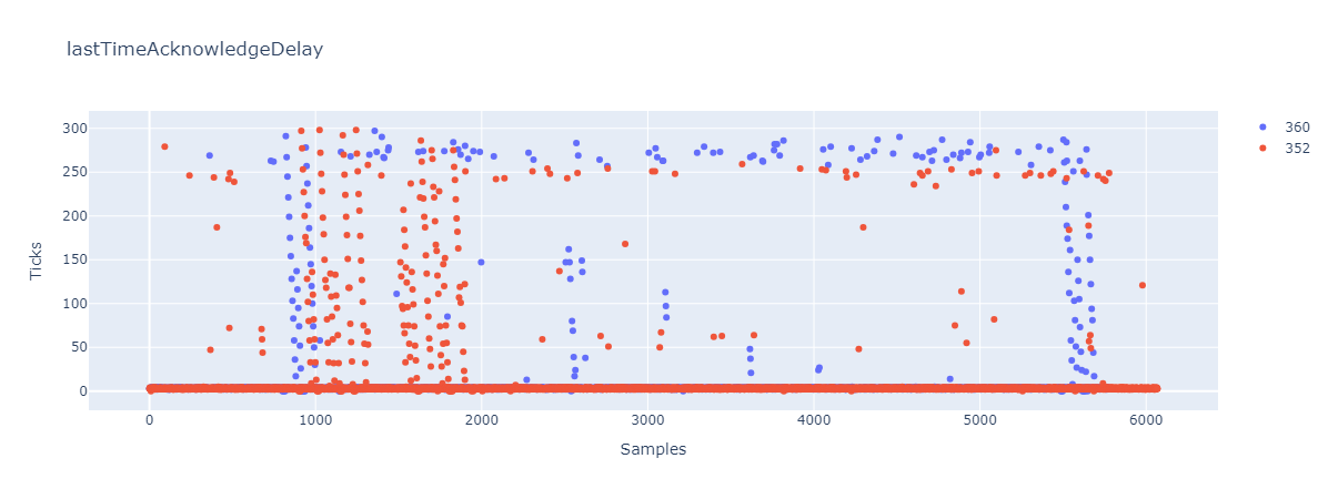
From the plots you can see that the behavior of
lastTimeAcknowledgeDelaywith FW 3.5.2 and 3.6.0-beta.1 is similar, so I might never have had a shift before just because in 3.5.2 the movement commands weren't discarded.
I increasedMaxTimeSyncDelayfrom 300 (400 usec?) to 375 (500 usec?) to see what happens: these spikes are still present but the number of zeros is reduced, so hopefully tolerant enough to never reach 10 consecutive samples.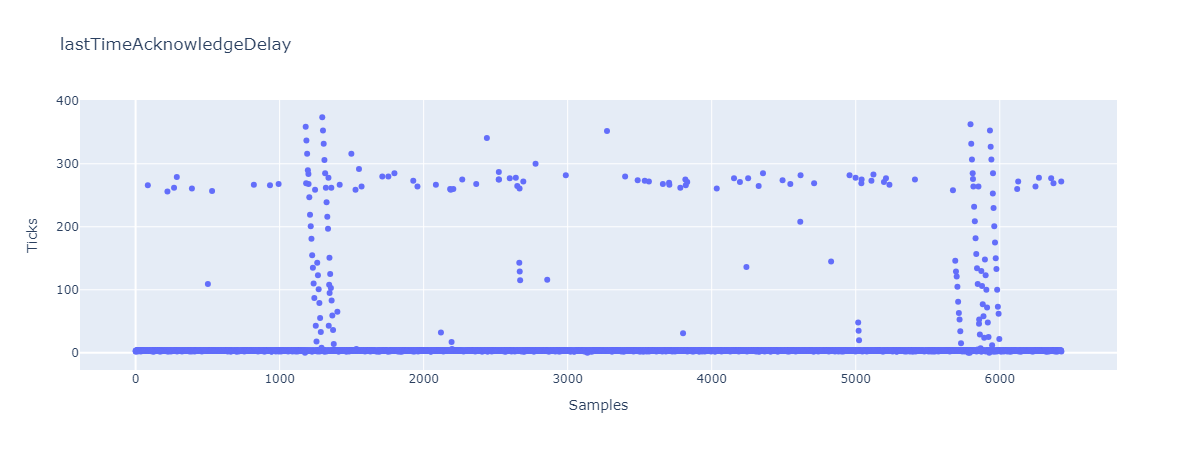
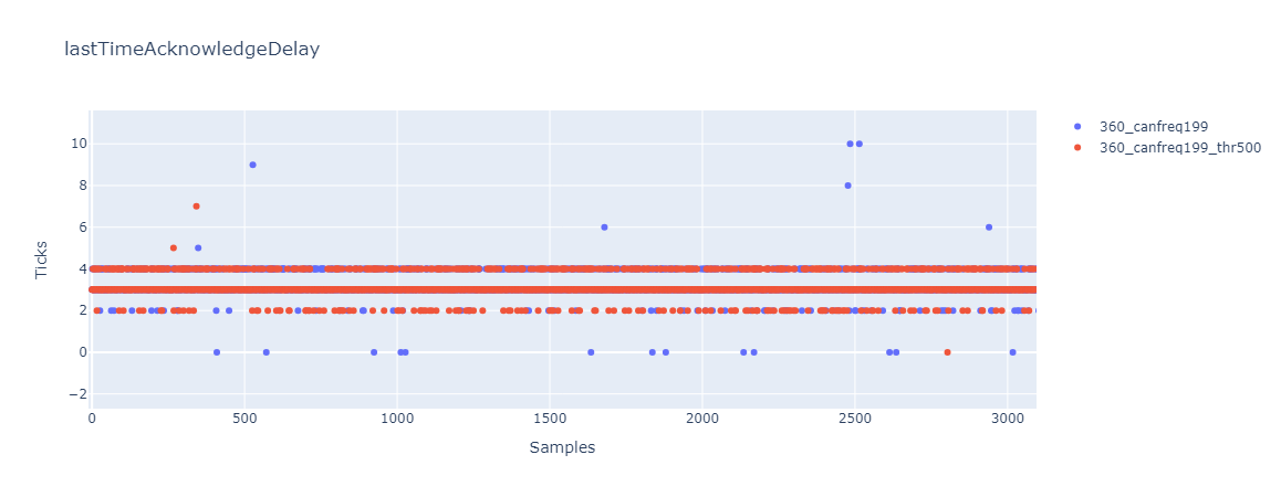
From the plot, it looks like the normal value for
lastTimeAcknowledgeDelayis around 3-5 and a cloudy distribution around 250-300. So the original threshold of 300 would make sense.
I'm wondering why there are these spikes, after one spike to about 300 or more, the spike is then repeated every 5 samples but with a linear decreasing amplitude.
I tried also to disable the input shaping but the overall distribution is similar.Do you have any explanation for this behavior? Other processes or interrupts interfering? Do you think it would make sense to increase the
MaxTimeSyncDelaythreshold or is it just a patch? Do you foresee any issues arising from doing this?Thanks in advance.
-
RE: Version 3.6.0-beta.2 now availableposted in Beta Firmware
Hi @chrishamm, I just noticed in the Git tree that the tag 3.6.0-beta.2 is pointing to a commit in the 3.5-dev branch (72d85117). Maybe the intended commit was 4cc23ddc in the 3.6-dev branch? Both have "Tidied up M307 processing" as message.
-
RE: [FW 3.5.2] M569.2 and microstepping lookup tableposted in Tuning and tweaking
@dc42 great news!
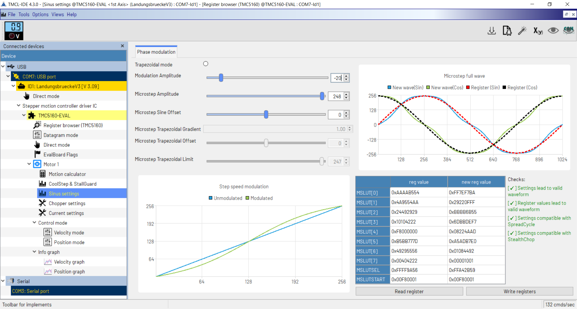
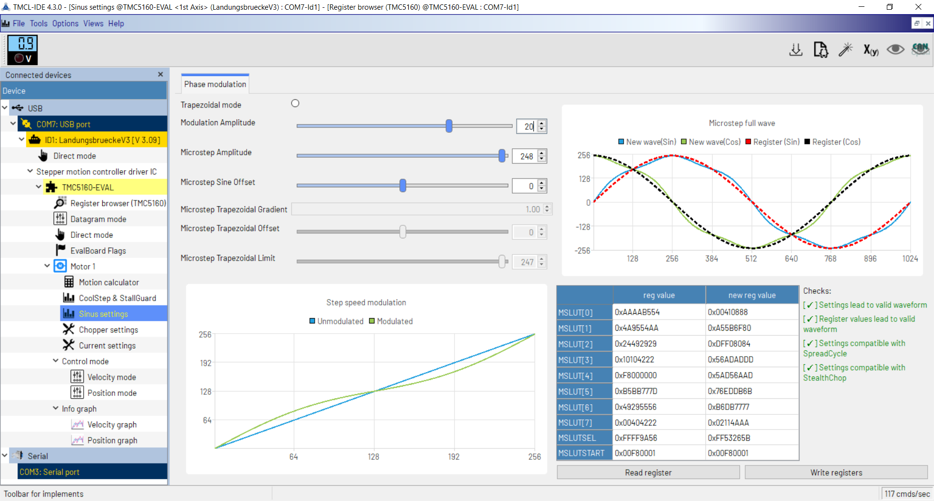
The modulation parameter goes from -27 to 39.
-
RE: [FW 3.5.2] M569.2 and microstepping lookup tableposted in Tuning and tweaking
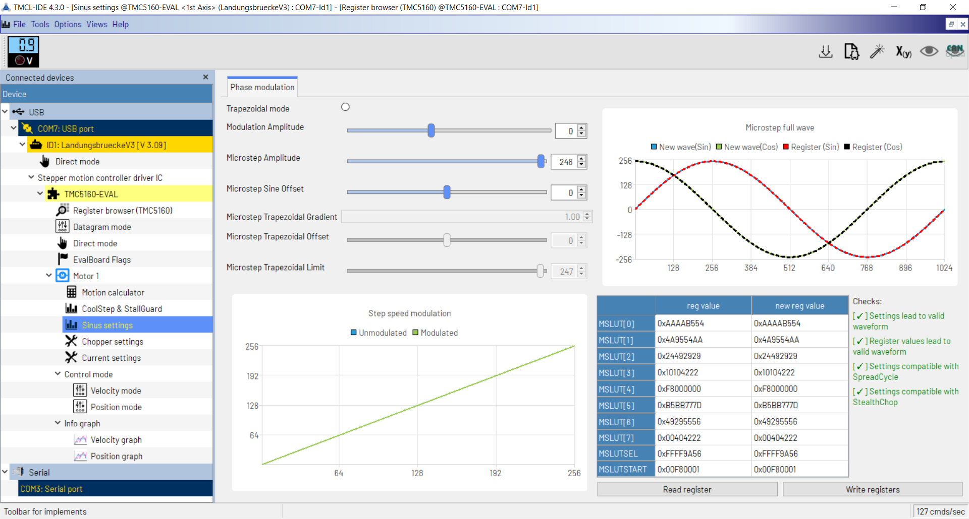
@dc42 unfortunately, the IDE doesn't say anything more than the datasheet/application notes.
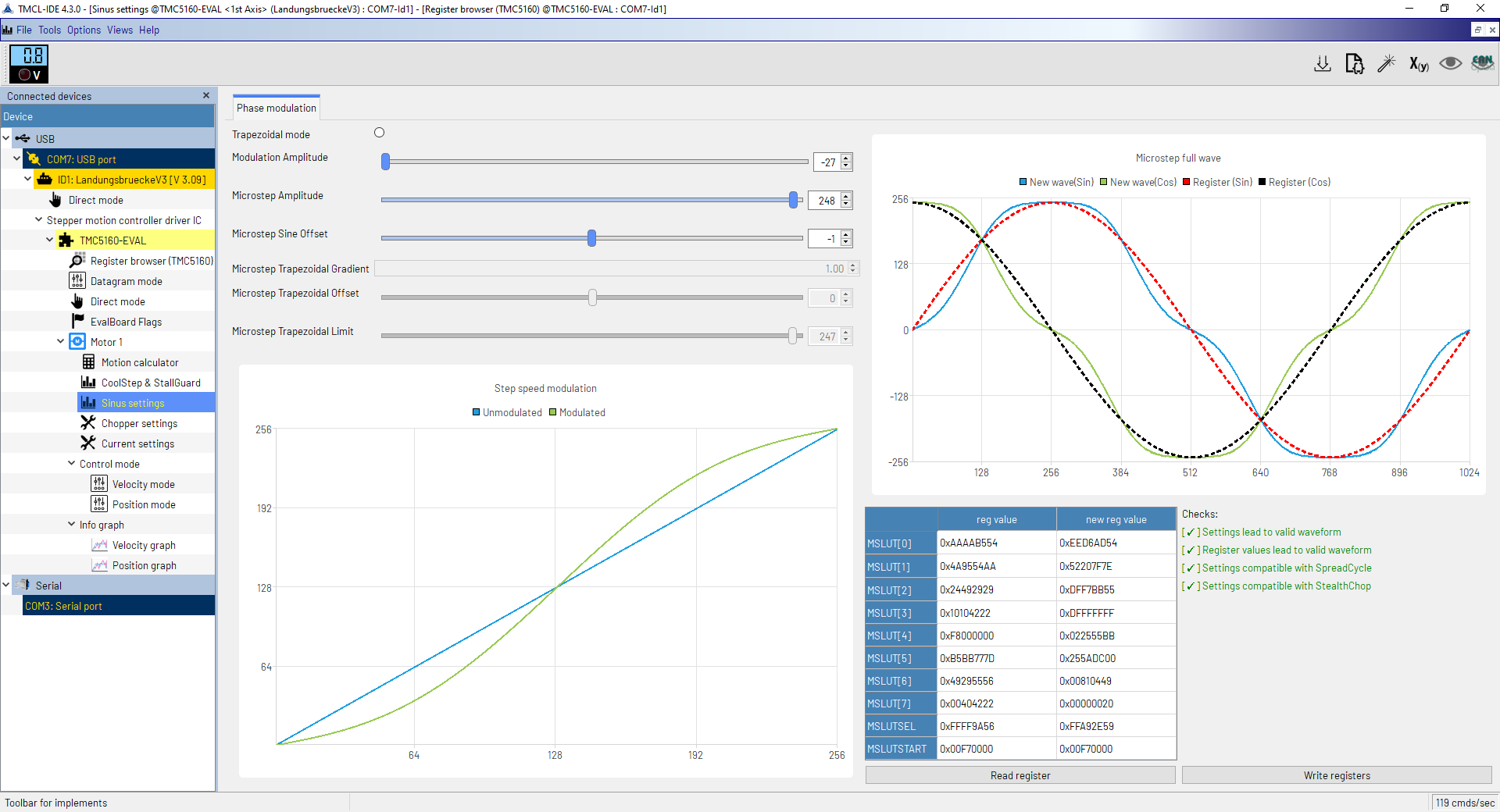
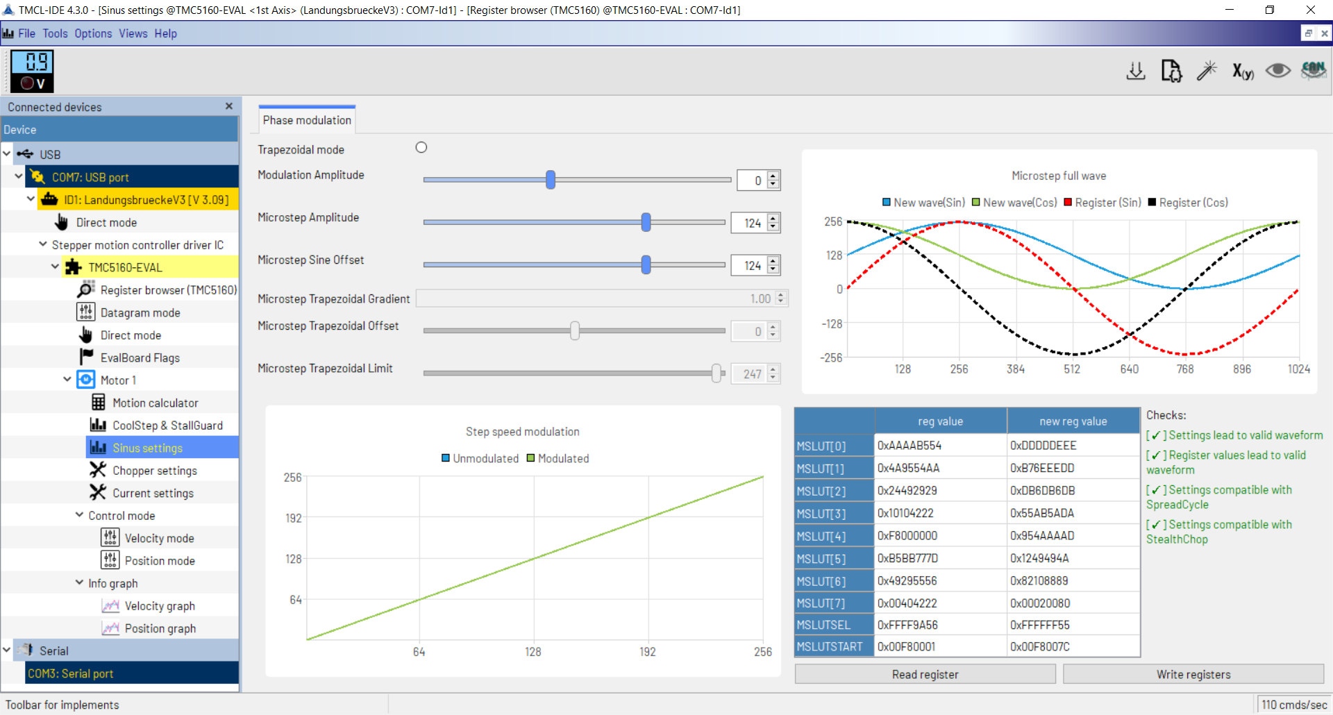
My understanding here is that the sine wave is encoded as a list of increments/decrements to add to the START_SIN and START_SIN90 registries while increasing the microsteps. Since START_SIN and START_SIN90 represent the current of the two coils at the beginning of the electrical revolution, the value has to be greater or equal than zero.
It can be tuned for some desired behaviours or to make some weird configurations feasible (as in the picture below, where for offset less than 28 the wave is not feasible).
In general, from the examples in the datasheet and application notes, I saw the START_SIN registry always set to zero.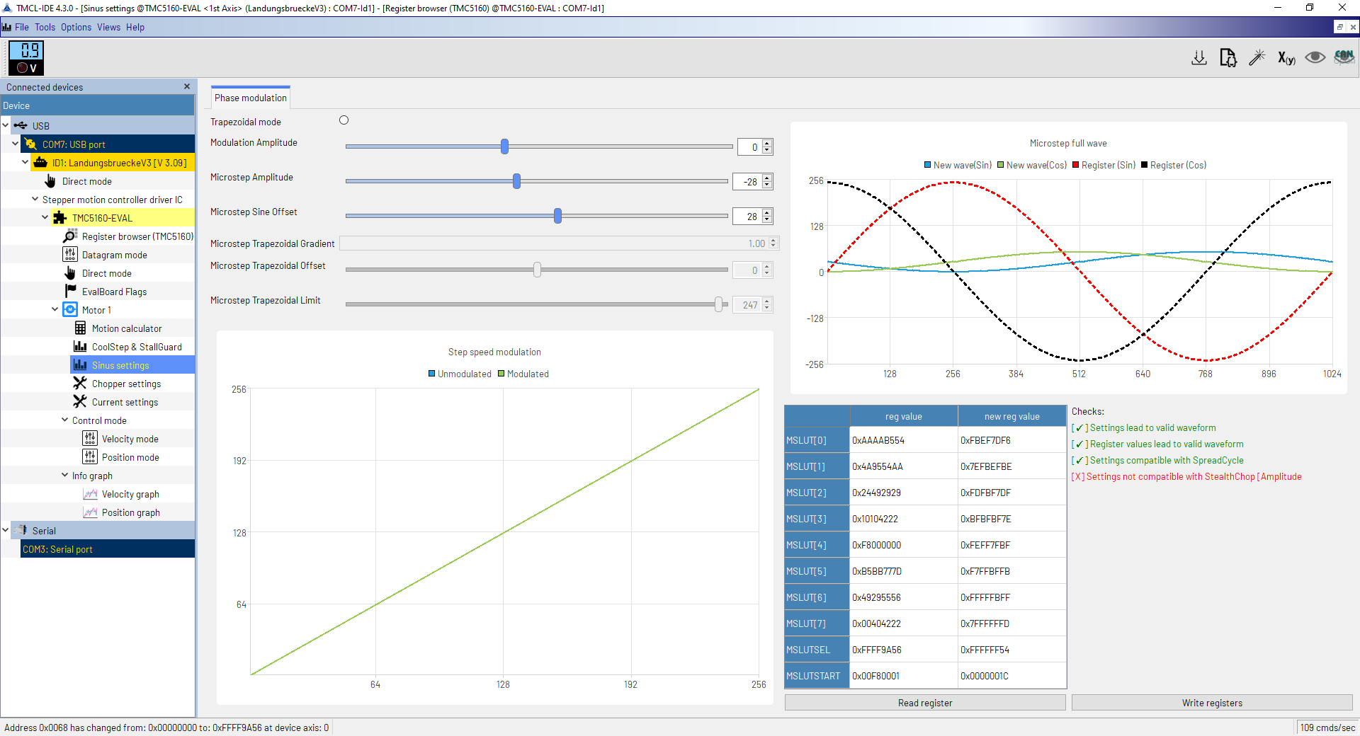
-
RE: [FW 3.5.2] M569.2 and microstepping lookup tableposted in Tuning and tweaking
@dc42 here they are. The sine offset should be "the absolute current at entry of the lookup table". It shifts up or down the sine wave, so to have it feasible I had to reduce the microstep amplitude. The maximum offset is not feasible, the higher it gets, the flatter the sinewave must be. Hope it's enough to clarify the behaviour, if you need something else, let me know.
-
RE: [FW 3.5.2] M569.2 and microstepping lookup tableposted in Tuning and tweaking
@AndyE3D I followed the driver's datasheet and the application note 26:
https://www.analog.com/en/resources/app-notes/an-026.html
https://www.analog.com/media/en/technical-documentation/data-sheets/TMC5160A_datasheet_rev1.17.pdf
These are settings strongly dependent on the motor itself, and I have only nema24 motors. The configuration I posted is the best I found for this type of motor. -
RE: [FW 3.5.2] M569.2 and microstepping lookup tableposted in Tuning and tweaking
@AndyE3D I am using the TMC5160 evaluation kit (https://www.mouser.de/ProductDetail/ADI-Trinamic/TMC5160-EVAL-KIT?qs=TiOZkKH1s2TJebvRqsmGsQ%3D%3D).
Once you connect the eval-kit to the pc you will find something called "sinus tool" and you can play with it. This is what in the user manual is called "microstepping look-up table"... I'm not sure if with "phase modulation" you're referring to the same thing.