Posts made by maor3degem.co.il
-
RE: Out of Sync for sync motors (same Axis)posted in General Discussion
@droftarts
Hi.another event.
it is certainly looks like 1 driver out of 4 of X axis lost his microsteping definition.
[M350 Lost for 1 of 4 X axis drivers.M122.txt config.g M350 Lost for 1 of 4 X axis drivers.mp4
attached is a video nd config + M122 output.
please advice.
this happen with multiple FW version (3.3 + 3.4.5 + 3.5.2)
this happen with drivers from the duet/duex; Configuration file for Duet WiFi (firmware version 3) ; executed by the firmware on start-up ; ; generated by RepRapFirmware Configuration Tool v3.2.3 on Sun Jun 06 2021 20:45:39 GMT+0300 (Israel Daylight Time) ; General preferences G90 ; send absolute coordinates... M83 ; ...but relative extruder moves M550 P"FT6_7" ; set printer name ; Network M552 S1 ; enable network M586 P0 S1 ; enable HTTP M586 P1 S0 ; disable FTP M586 P2 S0 ; disable Telnet M584 X3:4:5:6 Y0 Z8:7 E1:2 M671 X-220:740 Y175:175 S15 ; leadscrews at left (connected to Z) and right (connected to E1) of X axis ; Drives M569 P0 S0 ; Drive 0 goes forwards M569 P1 S1 ; Drive 1 goes backwards M569 P2 S1 ; Drive 2 goes backwards M569 P3 S1 ; Drive 3 goes forwards M569 P4 S0 ; Drive 4 goes backwards M569 P5 S0 ; Drive 5 goes forwards M569 P6 S1 ; Drive 6 goes forwards M569 P7 S0 ; Drive 7 goes forwards M569 P8 S0 ; Drive 8 goes forwards M569 P9 S0 ; Drive 9 goes forwards M350 X16 Y16 Z16 E16 I1 ; Configure microstepping with interpolation M92 X80.00 Y80.00 Z1440 E400 ; Set steps per mm M566 X900 Y900 Z24 E1200.00 ; Set maximum instantaneous speed changes (mm/min) M203 X12000.00 Y12000.00 Z720 E7200.00 ; Set maximum speeds (mm/min) M201 X1000.00 Y1000.00 Z500.00 E10000.00 ; Set accelerations (mm/s^2) M906 X1600.00 Y1200.00 Z1600.00 E750.00 I30; Set motor currents (mA) and motor idle factor in per cent M84 S30 ; Set idle timeout ; switch motor M950 P0 C"spi.cs1" M950 P1 C"spi.cs2" M950 P2 C"spi.cs3" ; Axis Limits M208 X0 Y0 Z0 S1 ; set axis minima M208 X750 Y350 Z750 S0 ; set axis maxima ; Endstops M574 X1 S1 P"!xstop" ; configure active-high endstop for low end on X via pin xstop M574 Y1 S1 P"!ystop" ; configure active-high endstop for low end on Y via pin ystop M574 Z1 S2 ; configure Z-probe endstop for low end on Z ;M591 D0 P3 C"e0_stop" S1 R70:130 L24.8 E1000 ; Duet3D rotating magnet sensor for extruder drive 0 is connected to E0 endstop input, enabled, sensitivity 24.8mm.rev, 70% to 130% tolerance, ;3mm detection length M591 D0 ; display filament sensor parameters for extruder drive 0 ;M591 P3 C"e0_stop" S1 D3 L3 E4 ; filament monitor connected to E0_stop ; Z-Probe M558 P1 C"zprobe.in" H5 F500:50 T6000 ; set Z probe type to unmodulated and the dive height + speeds G31 P500 X-10 Y25 Z0 ; set Z probe trigger value, offset and trigger height M557 X15:700 Y30:320 p20:14 ; define mesh grid M376 H50 ; Heaters M308 S0 P"bedtemp" Y"thermistor" T100000 B4092 ; configure sensor 0 as thermistor on pin bedtemp M950 H0 C"bedheat" T0 ; create bed heater output on bedheat and map it to sensor 0 M307 H0 ; enable bang-bang mode for the bed heater and set PWM limit M140 H0 ; map heated bed to heater 0 M143 H0 S150 ; set temperature limit for heater 0 to 150C M308 S1 P"e0temp" Y"thermistor" T100000 B4580 C7.06e-8 ; configure sensor 1 as thermistor on pin e0temp M950 H1 C"e0heat" T1 ; create nozzle heater output on e0heat and map it to sensor 1 M307 H1 B0 S1.00 ; disable bang-bang mode for heater and set PWM limit M143 H1 S400 ; set temperature limit for heater 1 to 275C M308 S2 P"e0temp" Y"thermistor" T100000 B4580 C7.06e-8 ; configure sensor 2 as thermistor on pin e1temp M950 H2 C"e0heat" T2 ; create nozzle heater output on e1heat and map it to sensor 2 M307 H2 B0 S1.00 ; disable bang-bang mode for heater and set PWM limit M143 H2 S400 ; set temperature limit for heater 2 to 275C M308 S3 P"e0temp" Y"thermistor" T100000 B4580 C7.06e-8 ; configure sensor 3 as thermistor on pin duex.e2temp M950 H3 C"e0heat" T3 ; create nozzle heater output on duex.e2heat and map it to sensor 3 M307 H3 B0 S1.00 ; disable bang-bang mode for heater and set PWM limit M143 H3 S400 ; set temperature limit for heater 3 to 275C M308 S4 P"e0temp" Y"thermistor" T100000 B4580 C7.06e-8 ; configure sensor 4 as thermistor on pin duex.e2temp M950 H4 C"e0heat" T4 ; create nozzle heater output on duex.e2heat and map it to sensor 4 M307 H4 B0 S1.00 ; disable bang-bang mode for heater and set PWM limit M143 H4 S400 ; set temperature limit for heater 4 to 275C M308 S5 P"e0temp" Y"thermistor" T100000 B4580 C7.06e-8 ; configure sensor 5 as thermistor on pin duex.e2temp M950 H5 C"e0heat" T5 ; create nozzle heater output on duex.e2heat and map it to sensor 5 M307 H5 B0 S1.00 ; disable bang-bang mode for heater and set PWM limit M143 H5 S400 ; set temperature limit for heater 5 to 275C ; Fans M950 F0 C"fan0" Q500 ; create fan 0 on pin fan0 and set its frequency M106 P0 S0 H-1 ; set fan 0 value. Thermostatic control is turned off M950 F1 C"fan1" Q500 ; create fan 1 on pin fan1 and set its frequency M106 P1 S1 H1 T45 ; set fan 1 value. Thermostatic control is turned on ; Tools M563 P0 D0:1 H1 F0 ; define tool 0 M567 P0 E1.0:1.0 M563 P1 D0:1 H1 F0 ; define tool 1 M567 P1 E1.0:1.0 M563 P2 D0:1 H1 F0 ; define tool 2 M567 P2 E1.0:1.0 M563 P3 D0:1 H1 F0 ; define tool 3 M567 P3 E1.0:1.0 M563 P4 D0:1 H1 F0 ; define tool 4 M567 P4 E1.0:1.0 M563 P5 D0:1 H1 F0 ; define tool 5 M567 P5 E1.0:1.0 G10 P0 X0 Y0 Z0 ; set tool 0 axis offsets G10 P1 X0 Y0 Z0 ; set tool 1 axis offsets G10 P2 X0 Y0 Z0 ; set tool 2 axis offsets G10 P3 X0 Y0 Z0 ; set tool 3 axis offsets G10 P4 X0 Y0 Z0 ; set tool 4 axis offsets G10 P5 X0 Y0 Z0 ; set tool 5 axis offsets G10 P0 R0 S0 ; set initial tool 0 active and standby temperatures to 0C G10 P1 R0 S0 ; set initial tool 1 active and standby temperatures to 0C G10 P2 R0 S0 ; set initial tool 2 active and standby temperatures to 0C G10 P3 R0 S0 ; set initial tool 2 active and standby temperatures to 0C G10 P4 R0 S0 ; set initial tool 2 active and standby temperatures to 0C G10 P5 R0 S0 ; set initial tool 2 active and standby temperatures to 0C ; Custom settings are not defined ; Miscellaneous M575 P1 S1 B57600 ; enable support for PanelDue M501 ; load saved parameters from non-volatile memory M911 S10 R11 P"M913 X0 Y0 G91 M83 G1 Z3 E-5 F1000" ; set voltage thresholds and actions to run on power loss -
RE: Out of Sync for sync motors (same Axis)posted in General Discussion
@maor3degem-co-il @Maestro
I double checked it and
the motor doesn't move 1/16 cycles than the other
both motors are define in the same axis so it is impossible to define different micro stepping for each motor. and when I typed M584 the machine return 1:16 micro stepping for those X axis drivers/motorsRegards
Maor -
RE: Out of Sync for sync motors (same Axis)posted in General Discussion
@Maestro
I double checked it and
the motor doesn't move 1/16 cycles than the other
both motors are define in the same axis so it is impossible to define different micro stepping for each motor. and when I typed M584 the machine return 1:16 micro stepping for those X axis drivers/motorsRegards
Maor -
RE: Out of Sync for sync motors (same Axis)posted in General Discussion
@droftarts
The driver error is due to the carriage fall cut the wire.by the way, the machine is on pause right now and I can see the problem of the motors. if I will restart the machine the problem will go a way till next time.
and before restart the is no evidence of changing in the configuration
-
RE: Out of Sync for sync motors (same Axis)posted in General Discussion
@maor3degem-co-il
we have 15 machine that look pretty much the same.
we used them for 4 years without any problem like this,
this start happen in the last 4 months...can heavy dust cause this?
-
RE: Out of Sync for sync motors (same Axis)posted in General Discussion
@droftarts Hi
thanks for your help,
in the second, the Z motor also turning different length , the same symptom as with the X axis. and the Z connected to the main board...in addition we face this problem with a few machines we have (5) and it is occur also in the main boards drivers.
please advice what else can help us to solve this problems
Regards
Maor -
RE: Out of Sync for sync motors (same Axis)posted in General Discussion
@Maestro
I alsothought this could be,
but. this 2 motor define as the same axis. so cannot be done.
and also I check the m350 and it remain OK as define in the config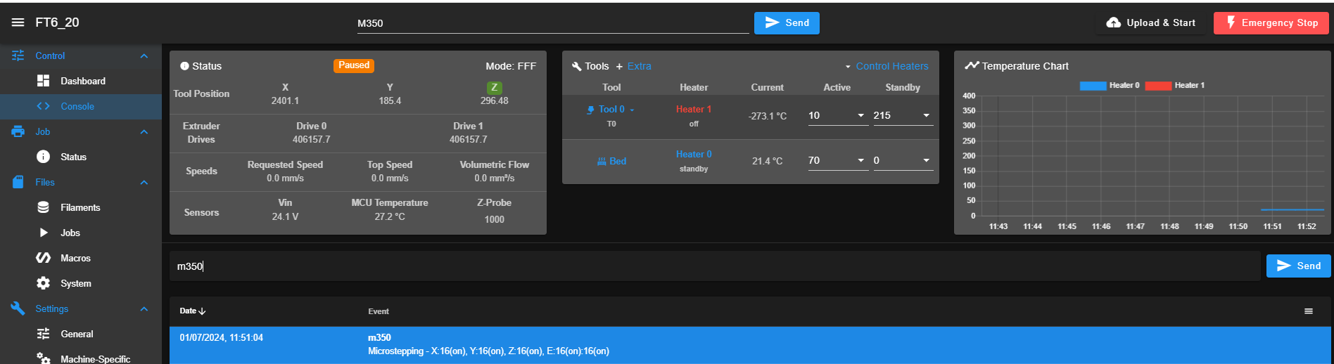
-
RE: Out of Sync for sync motors (same Axis)posted in General Discussion
@jay_s_uk
Here is again, 3 pairs of motor are out of sync.
config.g M122.txt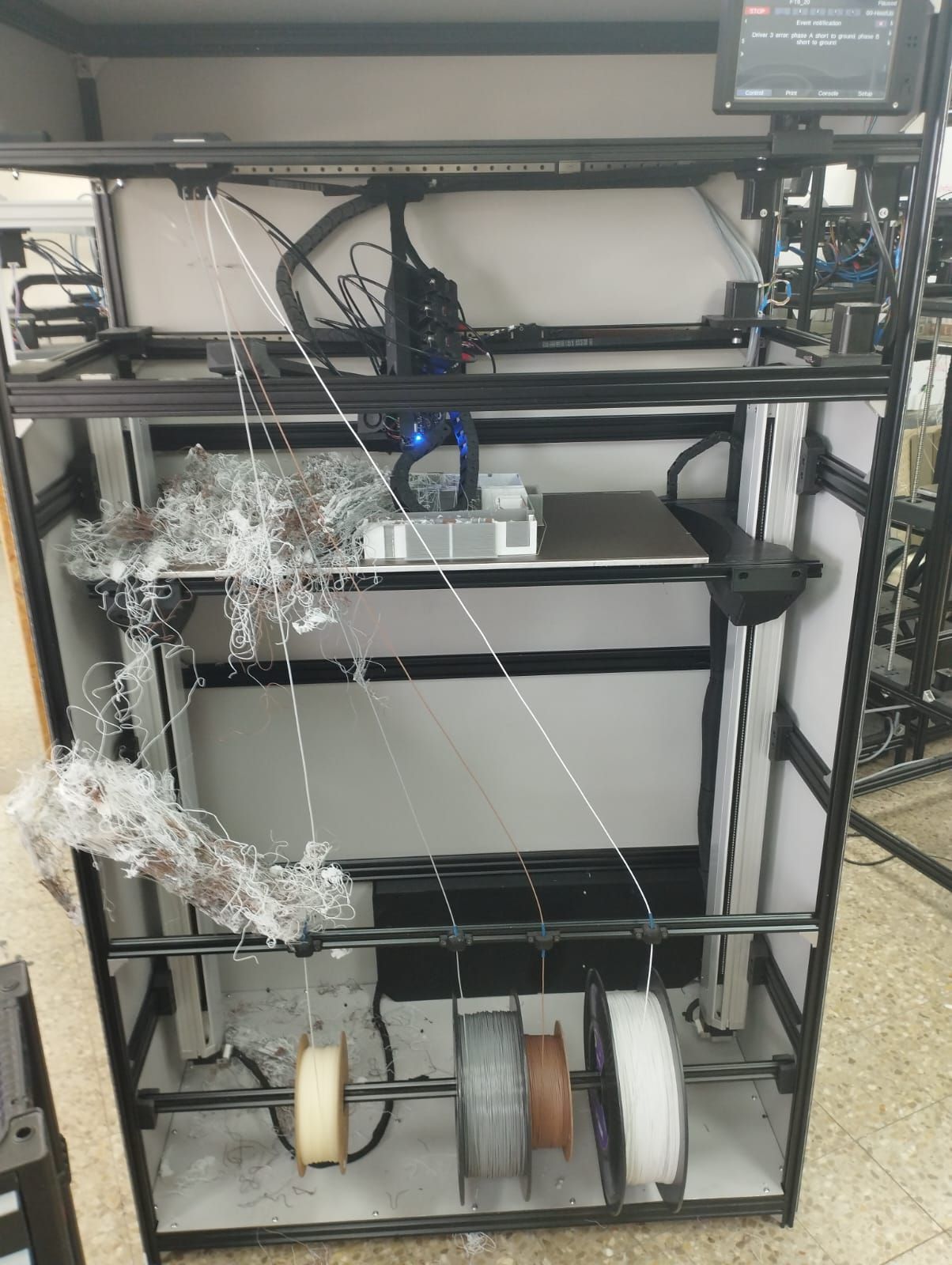 Vid.mp4
this is with the latest FW version 3.5.2
please advise
-
RE: Out of Sync for sync motors (same Axis)posted in General Discussion
@jay_s_uk
thanks
will do so and keep you posted -
RE: Out of Sync for sync motors (same Axis)posted in General Discussion
@jay_s_uk
Board: Duet 2 WiFi (2WiFi)
Firmware: RepRapFirmware for Duet 2 WiFi/Ethernet 3.3 (2021-06-15)
Duet WiFi Server Version: 1.26we did define 4/2 Z motor, depending on a specific machine
M584 X3 Y1:2 Z5:7:8:9 E4:0 -
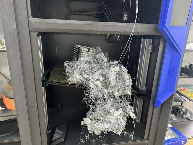
Out of Sync for sync motors (same Axis)posted in General Discussion
Dir all,
recently we face a wired problem.
we have 20 3d printer which has parallel x motor and parallel Z motor.
after a while the printer is working suddenly random motor out of sync which case him to move shorter distance in compare to the sync one.
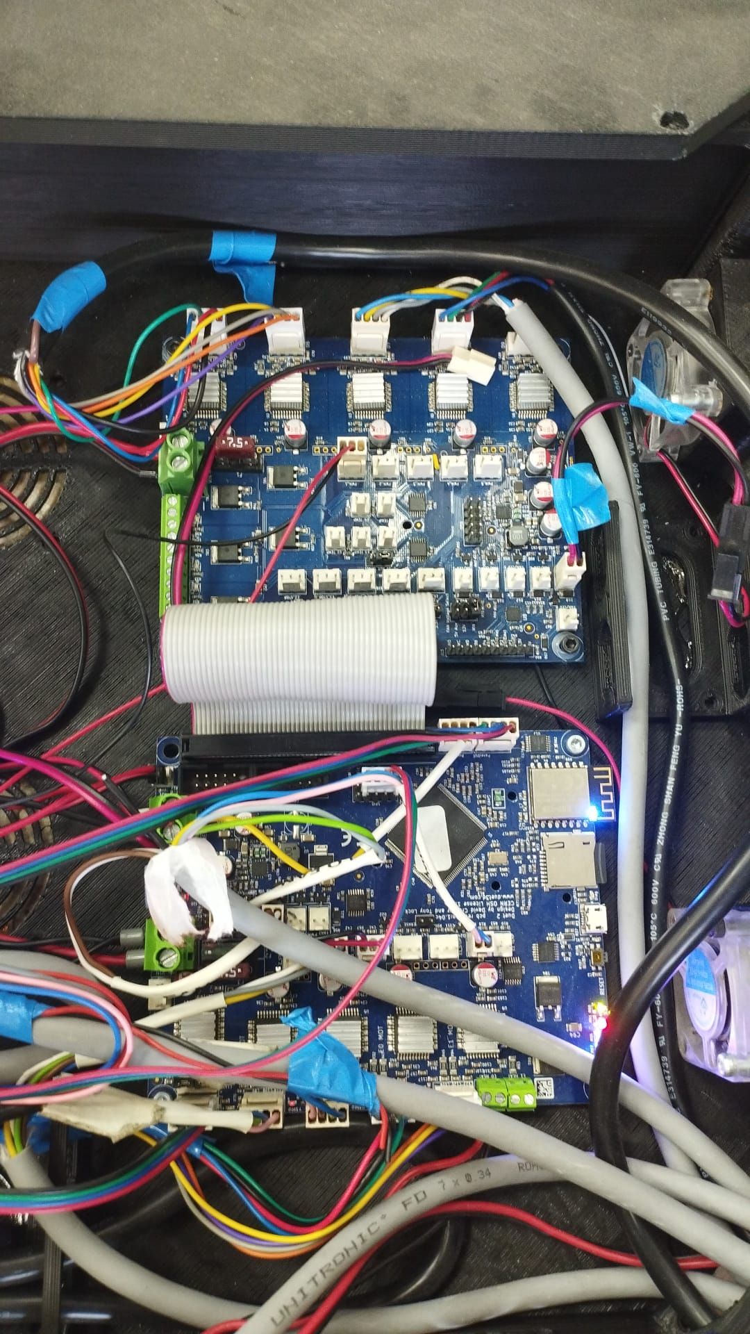
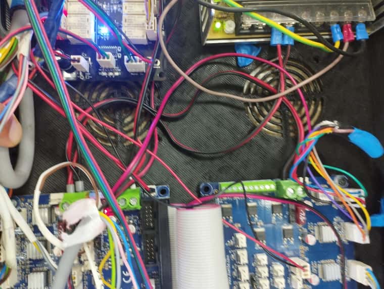
attached is a photo and a video.
after I restart the machine the problem goes a way till the next random occasion
this happen randomly in 5 3d printer from 20.Pic:
Video:
OutOFSyncZ (seperate Drivers).mp4Config:
config.g; Configuration file for Duet WiFi (firmware version 3.3) ; executed by the firmware on start-up ; ; generated by RepRapFirmware Configuration Tool v3.3.10 on Wed Mar 02 2022 19:03:35 GMT+0200 (Israel Standard Time) ; General preferences ;M575 P1 S1 B57600 ; enable support for PanelDue G90 ; send absolute coordinates... M83 ; ...but relative extruder moves M550 P"Trifolium" ; Set machine name ;M950 P3 C"exp.heater3" Q500 ;braks M42 P3 S1 ; Network M552 S1 ; Enable network M586 P0 S1 ; Enable HTTP M586 P1 S0 ; Enable FTP M586 P2 S0 ; Enable Telnet M587 S"Degem" P"Password123" M584 X3 Y1:2 Z5:7:8:9 E4:0 M671 X-200:1300:1300:-200 Y-200:-200:1300:1300 S1000 ; leadscrews at left (connected to Z) and right (connected to E1) of X axis ; Drives M569 P0 S1 ; Drive 0 goes forwards M569 P1 S0 ; Drive 1 goes forwards M569 P2 S1 ; Drive 2 goes forwards M569 P3 S1 ; Drive 3 goes backwards M569 P4 S1 ; Drive 4 goes backwards M569 P5 S1 ; Drive 5 goes backwards M569 P6 S1 ; Drive 6 goes backwards M569 P7 S1 ; Drive 6 goes backwards M569 P8 S1 ; Drive 6 goes backwards M569 P9 S1 ; Drive 6 goes backwards M350 X16 Y16 Z16 E16 I1 ; configure microstepping with interpolation M92 X97 Y97.00 Z640.00 E400.00 ; Set steps per mm M566 X600.00 Y600.00 Z24.00 E1200.00 ; Set maximum instantaneous speed changes (mm/min) M203 X24000.00 Y24000.00 Z1440.00 E7200.00 ; Set maximum speeds (mm/min) M201 X500.00 Y500.00 Z500.00 E10000.00 ; Set accelerations (mm/s^2) M906 X1800.00 Y1800.00 Z1800.00 E750.00 I30; Set motor currents (mA) and motor idle factor in per cent M84 S30 ; Set idle timeout ; switch motor M950 P0 C"spi.cs1" M950 P1 C"spi.cs2" M950 P2 C"spi.cs3" ; Axis Limits M208 X0 Y0 Z0 S1 ; set axis minima M208 X1100 Y1070 Z1135 S0 ; set axis maxima ; Endstops M574 X1 S1 P"!xstop" ; configure active-high endstop for low end on X via pin xstop M574 Y2 S1 P"!ystop" ; configure active-high endstop for low end on Y via pin ystop M574 Z1 S2 ; configure Z-probe endstop for low end on Z ;M591 D0 P3 C"e0_stop" S1 R70:130 L24.8 E1000 ; Duet3D rotating magnet sensor for extruder drive 0 is connected to E0 endstop input, enabled, sensitivity 24.8mm.rev, 70% to 130% tolerance, ;3mm detection length M591 D0 ; display filament sensor parameters for extruder drive 0 ;M591 P3 C"e0_stop" S1 D3 L3 E4 ; filament monitor connected to E0_stop ; Z-Probe M558 P1 C"zprobe.in" H5 F500 T6000 ; set Z probe type to unmodulated and the dive height + speeds G31 P500 X33 Y5 Z0.8 ; set Z probe trigger value, offset and trigger height M557 X50:1050 Y50:1050 p20:20 ; define mesh grid M376 H50 ; Heaters M308 S0 P"bedtemp" Y"thermistor" T100000 B4092 ; configure sensor 0 as thermistor on pin bedtemp M950 H0 C"bedheat" T0 ; create bed heater output on bedheat and map it to sensor 0 M307 H0 ; enable bang-bang mode for the bed heater and set PWM limit M140 H0 ; map heated bed to heater 0 M143 H0 S150 ; set temperature limit for heater 0 to 150C M308 S1 P"e0temp" Y"thermistor" T100000 B4580 C7.06e-8 ; configure sensor 1 as thermistor on pin e0temp M950 H1 C"e0heat" T1 ; create nozzle heater output on e0heat and map it to sensor 1 M307 H1 B0 S1.00 ; disable bang-bang mode for heater and set PWM limit M143 H1 S400 ; set temperature limit for heater 1 to 275C M308 S2 P"e0temp" Y"thermistor" T100000 B4580 C7.06e-8 ; configure sensor 2 as thermistor on pin e1temp M950 H2 C"e0heat" T2 ; create nozzle heater output on e1heat and map it to sensor 2 M307 H2 B0 S1.00 ; disable bang-bang mode for heater and set PWM limit M143 H2 S400 ; set temperature limit for heater 2 to 275C M308 S3 P"e0temp" Y"thermistor" T100000 B4580 C7.06e-8 ; configure sensor 3 as thermistor on pin duex.e2temp M950 H3 C"e0heat" T3 ; create nozzle heater output on duex.e2heat and map it to sensor 3 M307 H3 B0 S1.00 ; disable bang-bang mode for heater and set PWM limit M143 H3 S400 ; set temperature limit for heater 3 to 275C M308 S4 P"e0temp" Y"thermistor" T100000 B4580 C7.06e-8 ; configure sensor 4 as thermistor on pin duex.e2temp M950 H4 C"e0heat" T4 ; create nozzle heater output on duex.e2heat and map it to sensor 4 M307 H4 B0 S1.00 ; disable bang-bang mode for heater and set PWM limit M143 H4 S400 ; set temperature limit for heater 4 to 275C M308 S5 P"e0temp" Y"thermistor" T100000 B4580 C7.06e-8 ; configure sensor 5 as thermistor on pin duex.e2temp M950 H5 C"e0heat" T5 ; create nozzle heater output on duex.e2heat and map it to sensor 5 M307 H5 B0 S1.00 ; disable bang-bang mode for heater and set PWM limit M143 H5 S400 ; set temperature limit for heater 5 to 275C ; Fans M950 F0 C"fan0" Q500 ; create fan 0 on pin fan0 and set its frequency M106 P0 S0 H-1 ; set fan 0 value. Thermostatic control is turned off M950 F1 C"fan1" Q500 ; create fan 1 on pin fan1 and set its frequency M106 P1 S1 H1 T45 ; set fan 1 value. Thermostatic control is turned on ; Tools M563 P0 D0:1 H1 F0 ; define tool 0 M567 P0 E1.0:1.0 M563 P1 D0:1 H1 F0 ; define tool 1 M567 P1 E1.0:1.0 M563 P2 D0:1 H1 F0 ; define tool 2 M567 P2 E1.0:1.0 M563 P3 D0:1 H1 F0 ; define tool 3 M567 P3 E1.0:1.0 M563 P4 D0:1 H1 F0 ; define tool 4 M567 P4 E1.0:1.0 M563 P5 D0:1 H1 F0 ; define tool 5 M567 P5 E1.0:1.0 G10 P0 X0 Y0 Z0 ; set tool 0 axis offsets G10 P1 X0 Y0 Z0 ; set tool 1 axis offsets G10 P2 X0 Y0 Z0 ; set tool 2 axis offsets G10 P3 X0 Y0 Z0 ; set tool 3 axis offsets G10 P4 X0 Y0 Z0 ; set tool 4 axis offsets G10 P5 X0 Y0 Z0 ; set tool 5 axis offsets G10 P0 R0 S0 ; set initial tool 0 active and standby temperatures to 0C G10 P1 R0 S0 ; set initial tool 1 active and standby temperatures to 0C G10 P2 R0 S0 ; set initial tool 2 active and standby temperatures to 0C G10 P3 R0 S0 ; set initial tool 3 active and standby temperatures to 0C G10 P4 R0 S0 ; set initial tool 4 active and standby temperatures to 0C G10 P5 R0 S0 ; set initial tool 5 active and standby temperatures to 0C ; Custom settings are not defined ; Miscellaneous M575 P1 S1 B57600 ; enable support for PanelDue M501 ; load saved parameters from non-volatile memory M911 S10 R11 P"M913 X0 Y0 G91 M83 G1 Z3 E-5 F1000" ; set voltage thresholds and actions to run on power loss M17 M42 P3 S0regards
Maor