@dc42 i have also problem with u axis
when i restard main board u axis or tool locking motor won't work,
If i after reset go to config.g and press save with out any change and when pop up question
Cancel Restart mainboard run Config file
If i choose run Config file, then u axis (tool locking motor works)
Posts made by matej1006
-
RE: Error 292 S3posted in Tuning and tweaking
-
RE: Error 292 S3posted in Tuning and tweaking
; Configuration file for RepRapFirmware on Duet 3 Main Board 6HC
; executed by the firmware on start-up
;
; generated by RepRapFirmware Configuration Tool v3.5.0-beta.4 on Wed Jul 19 2023 13:39:45 GMT+0200 (Srednjeevropski poletni čas)

M98 P"Turn_printer_on"

; General #############################################################################################################
M550 P"3D MONSTRUM" 						; set hostname

; Network #############################################################################################################
M552 P192.168.0.39 S1 						; configure Ethernet adapter
M586 P0 S1 									; configure HTTP

; Wait a moment for the CAN expansion boards to become available ######################################################
G4 S2

; Smart Drivers #######################################################################################################
M569 P0.0 S0 D2 						; driver 0.0 goes backwards (Z axis)
M569 P0.1 S0 D2 						; driver 0.1 goes backwards (Z axis)
M569 P0.2 S0 D2 						; driver 0.2 goes backwards (Z axis)
M569 P0.3 S0 D2 						; driver 0.3 goes backwards (X axis)
M569 P0.4 S0 D2 						; driver 0.4 goes backwards (Y axis)

M569 P121.0 S0 D2 						; driver 121.0 goes forwards (extruder 0)
M569 P122.0 S0 D2 						; driver 122.0 goes forwards (extruder 1)
M569 P123.0 S0 D2 						; driver 123.0 goes forwards (extruder 2)
M569 P124.0 S0 D2 						; driver 124.0 goes forwards (extruder 3)
M569 P125.0 S0 D2 						; driver 125.0 goes forwards (tool locking motor)

; NOTE: This is later generated in the Axes and/or Extruders section ##################################################
M906 X800 Y800 Z800 U1000 I30			; set motor driver currents
M906 E1200:1200:1500:1500 I10			; set motor driver currents

; Motor Idle Current Reduction ########################################################################################
M84 S30 								; set motor current idle timeout

; External Drivers ####################################################################################################
										; no external drivers mapped to axes or extruders

; Closed-Loop Drivers #################################################################################################
										; no drivers with encoders configured

; Kinematics ##########################################################################################################
M669 K1 								; configure CoreXY kinematics

; Axes ################################################################################################################
M584 X0.3 Y0.4 Z0.0:0.1:0.2 				; set axis mapping
M350 X16 Y16 Z16 I1 						; configure microstepping with interpolation
; NOTE: See Smart Drivers section for motor currents
M92 X80 Y80 Z1600 							; configure steps per mm
M208 S1 X0 Y0 Z0 							; set axis minima
M208 S0 X420 Y386 Z430 						; set axis maxima
M566 X900 Y900 Z12 							; set maximum instantaneous speed changes (mm/min)
M203 X6000 Y6000 Z300 						; set maximum speeds (mm/min)
M201 X800 Y800 Z60 							; set accelerations (mm/s^2)

; Extruders ###########################################################################################################
M584 E121.0:122.0:123.0:124.0 				; set extruder mapping
M350 E16:16:16:16 I1          				; configure microstepping with interpolation
; NOTE: See Smart Drivers section for motor currents
M92 E690:690:2812:2812	     				; configure steps per mm
M566 E300:300:2812:2812    					; set maximum instantaneous speed changes (mm/min)
M203 E7200:7200:3600:3600     				; set maximum speeds (mm/min)
M201 E3000:3000:1500:1500      				; set accelerations (mm/s^2)

M572 D0 S0.02                 				;pressure advance – to be calibrated
M207 S1.5 F7200 Z0.2     					;firmware retraction

; Tool actuator ######################################################################################################
M584 U125.0 								; set extruder mapping
M350 U4 I1 									; configure microstepping with interpolation
; NOTE: See Smart Drivers section for motor currents
M92  U30.578     							; configure steps per mm
M566 U50   									; set maximum instantaneous speed changes (mm/min)
M203 U9000  								; set maximum speeds (mm/min)
M201 U900 I60  								; set accelerations (mm/s^2)
M208 U0:200

; Probes #############################################################################################################
M558 P9 C"125.io0.in" H5 F120 T6000                                 ; configure BLTouch probe via slot #0
G31 P500 X0 Y0 Z0.7                                                     ; set Z probe trigger value, offset and trigger height
M950 S5 C"125.io0.out"                                                 ; create servo #0 for BLtouch

; Endstops ###########################################################################################################
M574 X1 P"125.pdec.a" S1 					; configure X axis endstop
M574 Y1 P"0.io1.in" S1 						; configure Y axis endstop
M574 Z1 S2
M574 U1 P"125.io1.in" S1 					; configure U axis endstop

; Mesh Bed Compensation ##############################################################################################
M557 X0:380 Y114:364 S40 					; define grid for mesh bed compensation

; Sensors ############################################################################################################
M308 S0 P"temp0" Y"thermistor" A"Heated Bed" T100000 B3950			 		; configure sensor #0
M308 S1 P"121.temp0" Y"thermistor" A"Nozzle 1" T100000 B4725 C7.06e-8 		; configure sensor #1
M308 S2 P"122.temp0" Y"thermistor" A"Nozzle 2" T100000 B4725 C7.06e-8 		; configure sensor #2
M308 S3 P"123.temp0" Y"thermistor" A"Nozzle 3" T100000 B4725 C7.06e-8 		; configure sensor #3
M308 S4 P"124.temp0" Y"thermistor" A"Nozzle 4" T100000 B4725 C7.06e-8 		; configure sensor #4
M308 S5 P"125.temp0" Y"thermistor" A"WATER IN TO COOLER" T10000 B3435 		; configure sensor #5
M308 S6 P"125.temp1" Y"thermistor" A"WATER OUT OF COOLER" T10000 B3435	 	; configure sensor #6

M308 S7 Y"drivers" P"1.dummy" A"DRIVERS"  ; configure sensor 2 as temperature warning and overheat flags on the TMC2660 on Duet
M308 S8 Y"mcu-temp" P"1.dummy" A"MCU" ; configure sensor 3 as on-chip MCU temperature sensor

M308 S9 P"121.temp1" Y"thermistor" A"WATER OUT T. HEAD 1" T10000 B3435	 	; configure sensor #7
M308 S10 P"122.temp1" Y"thermistor" A"WATER OUT T. HEAD 2" T10000 B3435	 	; configure sensor #8
M308 S11 P"123.temp1" Y"thermistor" A"WATER OUT T. HEAD 3" T10000 B3435	 	; configure sensor #9
M308 S12 P"124.temp1" Y"thermistor" A"WATER OUT T. HEAD 4" T10000 B3435	 	; configure sensor #10
; Heaters ############################################################################################################
M950 H0 C"out0" T0 							; create heater #0
M143 H0 P0 T0 C0 S110 A0 					; configure heater monitor #0 for heater #0
M307 H0 R2.43 D5.5 E1.35 K0.56 B1 			; configure model of heater #0
M140 H0 R35 								; map heated bed to heater 0

M950 H1 C"121.out0" T1 						; create heater #1
M143 H1 P0 T1 C0 S250 A0 					; configure heater monitor #0 for heater #1
M307 H1 R2.43 D5.5 E1.35 K0.56 B0 			; configure model of heater #1

M950 H2 C"122.out0" T2 						; create heater #2
M143 H2 P0 T1 C0 S250 A0 					; configure heater monitor #0 for heater #2
M307 H2 R2.43 D5.5 E1.35 K0.56 B0 			; configure model of heater #2

M950 H3 C"123.out0" T3 						; create heater #3
M143 H3 P0 T1 C0 S250 A0 					; configure heater monitor #0 for heater #3
M307 H3 R2.43 D5.5 E1.35 K0.56 B0 			; configure model of heater #3

M950 H4 C"124.out0" T4 						; create heater #4
M143 H4 P0 T1 C0 S250 A0 					; configure heater monitor #0 for heater #4
M307 H4 R2.43 D5.5 E1.35 K0.56 B0 			; configure model of heater #4

; Heated beds #######################################################################################################
M140 P0 H0 ; configure heated bed #0

; Fans  #############################################################################################################
M950 F0 C"!out6+out6.tach" Q450								; create fan #0
M106 P0 C"MAIN BOARD NOCTUA" S1 L0.15 X1 B0.3 H7:8 T25:35 	; configure fan #0

M950 F1 C"out7" 											; create fan #1
M106 P1 C"BERDAIR PUMP" S0 L0 X1							; configure fan #1

M950 F2 C"!out5+out5.tach" Q25000 						    ; create fan #2
M106 P2 C"COLLER NOCTUA FANS" S1 L0.5 X1 B0.3 H5 T40:60		; configure fan #2

M950 F3 C"!out4+out4.tach"          				     	; create fan #3
M106 P3 C"WATER PUMP" S1 L0.35 X1 B0.3 H6 T20:60      		; configure fan #3

; Tools #############################################################################################################
M563 P0 D0 H1 F1 S"TOOL 1"					; create tool #0
G10 P0 Z4.922 								; Set tool #0 offset from the bed
M568 P0 R20 S30 							; set initial tool #0 active and standby temperatures to 0C

M563 P1 D1 H2 F1 S"TOOL 2"					; create tool #1
G10 P1 Z4.947 								; Set tool #1 offset from the bed with tool-0 as a reference.
M568 P1 R20 S30 							; set initial tool #1 active and standby temperatures to 0C

M563 P2 D2 H3 F1 S"TOOL 3"				; create tool #2
G10 P2 Z-3.75                   			; Set tool #2 offset from the bed
M568 P2 R20 S30 							; set initial tool #2 active and standby temperatures to 0C

M563 P3 D3 H4 F1 S"TOOL 4"					; create tool #3
G10 P3 Z-3.75                    			; Set tool #3 offset from the bed
M568 P3 R20 S30								; set initial tool #3 active and standby temperatures to 0C

; Emergen1cy Stop ##################4##################################################################################
M950 J1 C"!io0.in"               			; Define Emergency endstop - emergency stop switch condition
M581 P1 S0 T2                   			; Define action to be taken with activation of emergency stop switch
M582 T2 S0 									; set trigger #2 pending unconditionall


M950 J2 C"^121.io0.in"						; define logical input for filament auto load TOOL1
M581 P2 T3 S0 R0 							; define trigger for filament auto load triggers trigger3.g
M950 J3 C"^121.io2.in"						; define logical input for filament unload TOOL1
M581 P3 T4 S0 R0 							; define trigger for filament auto load triggers trigger4.g

M950 J4 C"^122.io0.in"						; define logical input for filament auto load TOOL2
M581 P4 T5 S0 R0 							; define trigger for filament auto load triggers trigger3.g
M950 J5 C"^122.io2.in"						; define logical input for filament unload TOOL2
M581 P5 T6 S0 R0 							; define trigger for filament auto load triggers trigger4.g
; bed.g ; called to perform automatic bed compensation via G32 ; ; generated by RepRapFirmware Configuration Tool v2.0.4 on Sat Oct 12 2019 15:44:24 GMT+0200 (Srednjeevropski poletni čas) T-1 ; remove tool M561 ; Disable any Mesh Bed Compensation G30 P0 X0 Y76 Z-99999 ; Probe near Front left leadscrew G30 P1 X184 Y355 Z-99999 ; PROBE POINT 2 back middle G30 P2 X370 Y76 Z-99999 S3 ; PROBE POINT 3 Front right G29 S1 ; Enable Mesh Bed Compensation -
Error 292 S3posted in Tuning and tweaking
M292 S3
Error: This kinematics does not support auto-calibrationi have M669 set to K1 because i have Core XY.
Today at first start of Duet3 6HC board i did notification that kinematic does not support auto calibrationi have 3 z motor to control height of table/bed
in previous board did this work with out problem.
-
RE: Digital input problem's / pwm signal outputposted in Tuning and tweaking
@infiniteloop yes ok that i know. i just didn't know what cca temp i would like to have in system running.
-
RE: Digital input problem's / pwm signal outputposted in Tuning and tweaking
@infiniteloop so now i have temp. set to hold between 20 to 25 C.
what would you recommend to set between 50 to 60 C -
RE: Digital input problem's / pwm signal outputposted in Tuning and tweaking
@dc42 damm i missed this info sorry

-
RE: Digital input problem's / pwm signal outputposted in Tuning and tweaking
@infiniteloop ok yeah that far i wasn't thinking yeah
-
RE: Digital input problem's / pwm signal outputposted in Tuning and tweaking
@deckingman no i want to when it goes form 3.3 to 0. i did add a resistor 10kohm to gnd and io0.in. isn't helping and also i did try pull up in code nothing was working.
-
RE: Digital input problem's / pwm signal outputposted in Tuning and tweaking
@matej1006 here is also diagnose
m122 === Diagnostics === RepRapFirmware for Duet 3 MB6HC version 3.4.4+1 (2022-11-15 17:36:33) running on Duet 3 MB6HC v1.02 or later (standalone mode) Board ID: 08DJM-9P63L-DJMSS-6JTD0-3S46L-9UFZ8 Used output buffers: 3 of 40 (18 max) === RTOS === Static ram: 152740 Dynamic ram: 100312 of which 172 recycled Never used RAM 97448, free system stack 200 words Tasks: NETWORK(ready,29.7%,218) ETHERNET(notifyWait,0.1%,445) HEAT(notifyWait,0.0%,344) Move(notifyWait,0.0%,351) CanReceiv(notifyWait,0.1%,799) CanSender(notifyWait,0.0%,336) CanClock(delaying,0.0%,339) TMC(notifyWait,7.0%,91) MAIN(running,62.9%,925) IDLE(ready,0.3%,30), total 100.0% Owned mutexes: === Platform === Last reset 00:00:46 ago, cause: power up Last software reset at 2023-07-25 18:49, reason: User, GCodes spinning, available RAM 97448, slot 0 Software reset code 0x0003 HFSR 0x00000000 CFSR 0x00000000 ICSR 0x00400000 BFAR 0x00000000 SP 0x00000000 Task MAIN Freestk 0 n/a Error status: 0x00 Step timer max interval 127 MCU temperature: min 25.1, current 31.3, max 31.4 Supply voltage: min 24.0, current 24.0, max 24.1, under voltage events: 0, over voltage events: 0, power good: yes 12V rail voltage: min 11.8, current 12.2, max 12.5, under voltage events: 0 Heap OK, handles allocated/used 0/0, heap memory allocated/used/recyclable 0/0/0, gc cycles 0 Events: 0 queued, 0 completed Driver 0: standstill, SG min 0, mspos 8, reads 64014, writes 14 timeouts 0 Driver 1: standstill, SG min 0, mspos 8, reads 64015, writes 14 timeouts 0 Driver 2: standstill, SG min 0, mspos 8, reads 64015, writes 14 timeouts 0 Driver 3: standstill, SG min 0, mspos 8, reads 64016, writes 13 timeouts 0 Driver 4: standstill, SG min 0, mspos 8, reads 64016, writes 13 timeouts 0 Driver 5: standstill, SG min 0, mspos 8, reads 64018, writes 11 timeouts 0 Date/time: 2023-07-25 19:05:26 Slowest loop: 3.98ms; fastest: 0.06ms === Storage === Free file entries: 10 SD card 0 detected, interface speed: 25.0MBytes/sec SD card longest read time 2.3ms, write time 0.0ms, max retries 0 === Move === DMs created 125, segments created 0, maxWait 0ms, bed compensation in use: none, comp offset 0.000 === MainDDARing === Scheduled moves 0, completed 0, hiccups 0, stepErrors 0, LaErrors 0, Underruns [0, 0, 0], CDDA state -1 === AuxDDARing === Scheduled moves 0, completed 0, hiccups 0, stepErrors 0, LaErrors 0, Underruns [0, 0, 0], CDDA state -1 === Heat === Bed heaters 0 -1 -1 -1 -1 -1 -1 -1 -1 -1 -1 -1, chamber heaters -1 -1 -1 -1, ordering errs 0 === GCodes === Segments left: 0 Movement lock held by null HTTP is idle in state(s) 0 Telnet is idle in state(s) 0 File is idle in state(s) 0 USB is idle in state(s) 0 Aux is idle in state(s) 0 Trigger is idle in state(s) 0 Queue is idle in state(s) 0 LCD is idle in state(s) 0 SBC is idle in state(s) 0 Daemon is idle in state(s) 0 Aux2 is idle in state(s) 0 Autopause is idle in state(s) 0 Code queue is empty === CAN === Messages queued 463, received 3512, lost 0, boc 0 Longest wait 3ms for reply type 6053, peak Tx sync delay 621, free buffers 50 (min 49), ts 233/232/0 Tx timeouts 0,0,0,0,0,0 === Network === Slowest loop: 3.60ms; fastest: 0.03ms Responder states: HTTP(0) HTTP(0) HTTP(0) HTTP(0) HTTP(0) HTTP(0) FTP(0) Telnet(0) Telnet(0) HTTP sessions: 1 of 8 = Ethernet = State: active Error counts: 0 0 0 1 0 0 Socket states: 2 5 2 2 2 0 0 0 = WiFi = Network state is disabled WiFi module is disabled Failed messages: pending 2779096485, notready 2779096485, noresp 2779096485 Socket states: 0 0 0 0 0 0 0 0 === Multicast handler === Responder is inactive, messages received 0, responses 0 -
Digital input problem's / pwm signal outputposted in Tuning and tweaking
Hello i have problem that i can't read input or send out output signal
if i use optical end stop everything works fine i get detection.
Mean while i have tool locking mechanisem which have 2 end stop switches in serias with NC contact used. i have 3.3v from same connector and back to ( 1HCL board) and i can't read it.Same is for emergency stop on main board (6HC). i have 3.3V connected to COM on emergency contact and than signal back to io0.in.
here is config file:
; Configuration file for RepRapFirmware on Duet 3 Main Board 6HC
; executed by the firmware on start-up
;
; generated by RepRapFirmware Configuration Tool v3.5.0-beta.4 on Wed Jul 19 2023 13:39:45 GMT+0200 (Srednjeevropski poletni čas)

M98 P"Turn_printer_on"

; General #############################################################################################################
M550 P"3D MONSTRUM" 						; set hostname

; Network #############################################################################################################
M552 P192.168.0.39 S1 						; configure Ethernet adapter
M586 P0 S1 									; configure HTTP

; Wait a moment for the CAN expansion boards to become available ######################################################
G4 S2

; Smart Drivers #######################################################################################################
M569 P0.0 S0 D2 						; driver 0.0 goes backwards (Z axis)
M569 P0.1 S0 D2 						; driver 0.1 goes backwards (Z axis)
M569 P0.2 S0 D2 						; driver 0.2 goes backwards (Z axis)
M569 P0.3 S0 D2 						; driver 0.3 goes backwards (X axis)
M569 P0.4 S0 D2 						; driver 0.4 goes backwards (Y axis)

M569 P121.0 S0 D2 						; driver 121.0 goes forwards (extruder 0)
M569 P122.0 S0 D2 						; driver 122.0 goes forwards (extruder 1)
M569 P123.0 S0 D2 						; driver 123.0 goes forwards (extruder 2)
M569 P124.0 S0 D2 						; driver 124.0 goes forwards (extruder 3)
M569 P125.0 S1 D2 						; driver 125.0 goes forwards (extruder 4)

; NOTE: This is later generated in the Axes and/or Extruders section ##################################################
M906 X800 Y800 Z800 E1500:1500:1500:1500 U10 			; set motor driver currents

; Motor Idle Current Reduction ########################################################################################
M906 I30 							; set motor current idle factor
M84 S30 							; set motor current idle timeout

; External Drivers ####################################################################################################
									; no external drivers mapped to axes or extruders

; Closed-Loop Drivers #################################################################################################
									; no drivers with encoders configured

; Kinematics ##########################################################################################################
M669 K1 							; configure CoreXY kinematics

; Axes ################################################################################################################
M584 X0.3 Y0.4 Z0.0:0.1:0.2 				; set axis mapping
M350 X16 Y16 Z1600 I1 						; configure microstepping with interpolation
; NOTE: See Smart Drivers section for motor currents
M92 X80 Y80 Z400 							; configure steps per mm
M208 S1 X0 Y0 Z0 							; set axis minima
M208 S0 X420 Y386 Z450 						; set axis maxima
M566 X900 Y900 Z12 							; set maximum instantaneous speed changes (mm/min)
M203 X6000 Y6000 Z300 						; set maximum speeds (mm/min)
M201 X800 Y800 Z60 							; set accelerations (mm/s^2)

; Extruders ###########################################################################################################
M584 E121.0:122.0:123.0:124.0 				; set extruder mapping
M350 E16:16:16:16 I1          				; configure microstepping with interpolation
; NOTE: See Smart Drivers section for motor currents
M92 E1756:2812:1756:1756      				; configure steps per mm
M566 E1756:2812:1756:1756     				; set maximum instantaneous speed changes (mm/min)
M203 E3600:3600:3600:3600     				; set maximum speeds (mm/min)
M201 E1500:1500:1500:1500      				; set accelerations (mm/s^2)

; Tool actuator ######################################################################################################
M584 U125.0 								; set extruder mapping
M350 U4 I1 									; configure microstepping with interpolation
; NOTE: See Smart Drivers section for motor currents
M92 U30.578     							; configure steps per mm
M566 U50   									; set maximum instantaneous speed changes (mm/min)
M203 U7000  								; set maximum speeds (mm/min)
M201 U800   								; set accelerations (mm/s^2)
M208 U0:200

; Probes #############################################################################################################

; Endstops ###########################################################################################################
M574 X1 P"125.pdec.a" S1 					; configure X axis endstop
M574 Y1 P"0.io1.in" S1 						; configure Y axis endstop
M574 Z1 S2
M574 U1 P"125.io1.in" S1 					; configure U axis endstop

; Mesh Bed Compensation ##############################################################################################
M557 X0:380 Y114:364 S40 					; define grid for mesh bed compensation

; Sensors ############################################################################################################
M308 S0 P"temp0" Y"thermistor" A"Heated Bed" T100000 B3950			 		; configure sensor #0
M308 S1 P"121.temp0" Y"thermistor" A"Nozzle 1" T100000 B4725 C7.06e-8 		; configure sensor #1
M308 S2 P"122.temp0" Y"thermistor" A"Nozzle 2" T100000 B4725 C7.06e-8 		; configure sensor #2
M308 S3 P"123.temp0" Y"thermistor" A"Nozzle 3" T100000 B4725 C7.06e-8 		; configure sensor #3
M308 S4 P"124.temp0" Y"thermistor" A"Nozzle 4" T100000 B4725 C7.06e-8 		; configure sensor #4
M308 S5 P"125.temp0" Y"thermistor" A"WATER IN TO COOLER" T10000 B3435 		; configure sensor #5
M308 S6 P"125.temp1" Y"thermistor" A"WATER OUT OF COOLER" T10000 B3435	 	; configure sensor #6

M308 S7 Y"drivers" A"DRIVERS"  ; configure sensor 2 as temperature warning and overheat flags on the TMC2660 on Duet
M308 S8 Y"mcu-temp" A"MCU" ; configure sensor 3 as on-chip MCU temperature sensor

; Heaters ############################################################################################################
M950 H0 C"out0" T0 							; create heater #0
M143 H0 P0 T0 C0 S110 A0 					; configure heater monitor #0 for heater #0
M307 H0 R2.43 D5.5 E1.35 K0.56 B1 			; configure model of heater #0
M140 H0 R35 								; map heated bed to heater 0

M950 H1 C"121.out0" T1 						; create heater #1
M143 H1 P0 T1 C0 S250 A0 					; configure heater monitor #0 for heater #1
M307 H1 R2.43 D5.5 E1.35 K0.56 B0 			; configure model of heater #1

M950 H2 C"122.out0" T2 						; create heater #2
M143 H2 P0 T1 C0 S250 A0 					; configure heater monitor #0 for heater #2
M307 H2 R2.43 D5.5 E1.35 K0.56 B0 			; configure model of heater #2

M950 H3 C"123.out0" T3 						; create heater #3
M143 H3 P0 T1 C0 S250 A0 					; configure heater monitor #0 for heater #3
M307 H3 R2.43 D5.5 E1.35 K0.56 B0 			; configure model of heater #3

M950 H4 C"124.out0" T4 						; create heater #4
M143 H4 P0 T1 C0 S250 A0 					; configure heater monitor #0 for heater #4
M307 H4 R2.43 D5.5 E1.35 K0.56 B0 			; configure model of heater #4

; Heated beds #######################################################################################################
M140 P0 H0 ; configure heated bed #0

; Fans  #############################################################################################################
M950 F0 C"!out6+out6.tach" Q450								; create fan #0
M106 P0 C"MAIN BOARD NOCTUA" S1 L0.15 X1 B0.3 H7:8 T25:35 	; configure fan #0

M950 F1 C"out7" 											; create fan #1
M106 P1 C"BERDAIR PUMP" S0 L0 X1							; configure fan #1

M950 F2 C"!out5+out5.tach" Q25000 						    ; create fan #2
M106 P2 C"COLLER NOCTUA FANS" S1 L0.5 X1 B0.3 H5 T25:35  	; configure fan #2

M950 F3 C"!out4+out4.tach"          				     	; create fan #3
M106 P3 C"WATER PUMP" S1 L0.35 X1 B0.3 H6 T20:70      		; configure fan #3

; Tools #############################################################################################################
M563 P0 D0 H1 F1 S"TOOL 1"					; create tool #0
G10 P0 Z4.922 								; Set tool #0 offset from the bed
M568 P0 R20 S30 							; set initial tool #0 active and standby temperatures to 0C

M563 P1 D1 H2 F1 S"TOOL 2"					; create tool #1
G10 P1 Z4.947 								; Set tool #1 offset from the bed with tool-0 as a reference.
M568 P1 R20 S30 							; set initial tool #1 active and standby temperatures to 0C

M563 P2 D552 H3 F1 S"TOOL 3"				; create tool #2
G10 P2 Z-3.75                   			; Set tool #2 offset from the bed
M568 P2 R20 S30 							; set initial tool #2 active and standby temperatures to 0C

M563 P3 D3 H4 F1 S"TOOL 4"					; create tool #3
G10 P3 Z-3.75                    			; Set tool #3 offset from the bed
M568 P3 R20 S30								; set initial tool #3 active and standby temperatures to 0C

; Emergen1cy Stop ##################4##################################################################################
M950 J1 C"io0.in"               			; Define Emergency endstop - emergency stop switch condition
M950 P4 C"io0.out"
M581 P1 S0 T2                   			; Define action to be taken with activation of emergency stop switch
M582 T2 S0 									; set trigger #3 pending unconditionally
other problem or isn't it. i would like that if temp go up then i would like that to pwm signal goes in to slower mode not faster.
just because when i cooling water i want that to flow through cooler slower. that i will get more heat out of water. -
RE: EMERGENCY STOPposted in Tuning and tweaking
@Phaedrux yeah i know that i mean M112.
but why i don't get any input reading
also i have problem on 1HCL i can't read end stop for tool locking mech.
i have two micro switch in serias with NC. And when i press on end stop switch nothing happend od DWC.I have problem with input's and output's.
-
EMERGENCY STOPposted in Tuning and tweaking
Hello
i can't figurit out what is wrong
i would also like to when is pressed emergency that i get output activated.
this is my config.g code
; Emergen1cy Stop ##################4##################################################################################
M950 J1 C"io0.in"               			; Define Emergency endstop - emergency stop switch condition
M950 P0 C"io0.out"
M581 P1 S0 T1                   			; Define action to be taken with activation of emergency stop switch
M582 T1 S1 									; set trigger #3 pending unconditionally
and this trigger1.g
;trigger1.g
M999
M42 P0 S1
nothing happend when i press
i have 3.3V to com and NC back to input with 10Kohm ressistor to gnd
-
RE: Duet 3 Expansion 1HCL tacho readingposted in Tuning and tweaking
; Water colling PUMP
M950 F2 C"!Fan0" Q25000 										; fan 2 is a 4-wire PWM fan so invert it, use high PWM frequency, tacho connected to PB6 on expansion connector
M106 P2 H5 I1 T20:25 L255                                       ; set fan 2 value. Thermostatic control is turned on
This is my code from duet2 eth board
Now I have duet3 6hc
I try same code and it wasn't workIf I swap noctua fans with pump fans works on this output out6 pump on out5 is same nothing from her
That I didn't try I Will tommorow
-
RE: Duet 3 Expansion 1HCL tacho readingposted in Tuning and tweaking
@dc42 it is 12Vdc 17W pump which can be connected directly to pc Mother board
I did try to invert and pullup and nothing was different -
RE: Duet 3 Expansion 1HCL tacho readingposted in Tuning and tweaking
@dc42
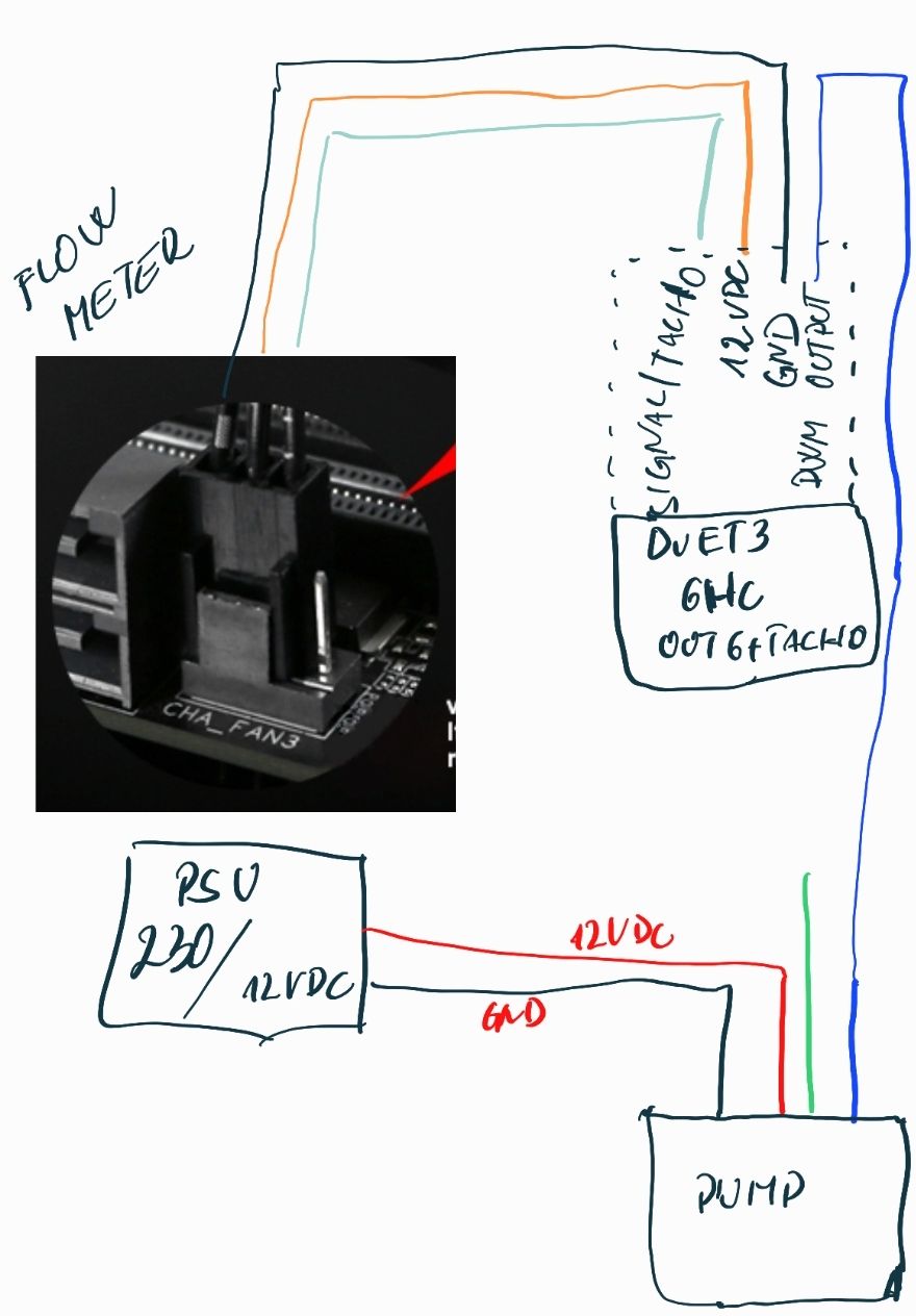 this is how have now connected all . And pump won't start! GND is commom
 -
RE: Duet 3 Expansion 1HCL tacho readingposted in Tuning and tweaking
@dc42 if i connect 12v directly from power supply tacho won't work ?
-
RE: Duet 3 Expansion 1HCL tacho readingposted in Tuning and tweaking
@dc42 it is a 12V pc Water colling so i think it will be ok but i will check just to be sure about it
-
RE: Duet 3 Expansion 1HCL tacho readingposted in Tuning and tweaking
@dc42 can I use OUT 0 and OUT 1 on tisti same board for PWM controlling my noctua fans and water pump. Will be same as fan pwm output?
-
RE: New ConfigTool v3.5.0-beta.3 availableposted in Config Tool
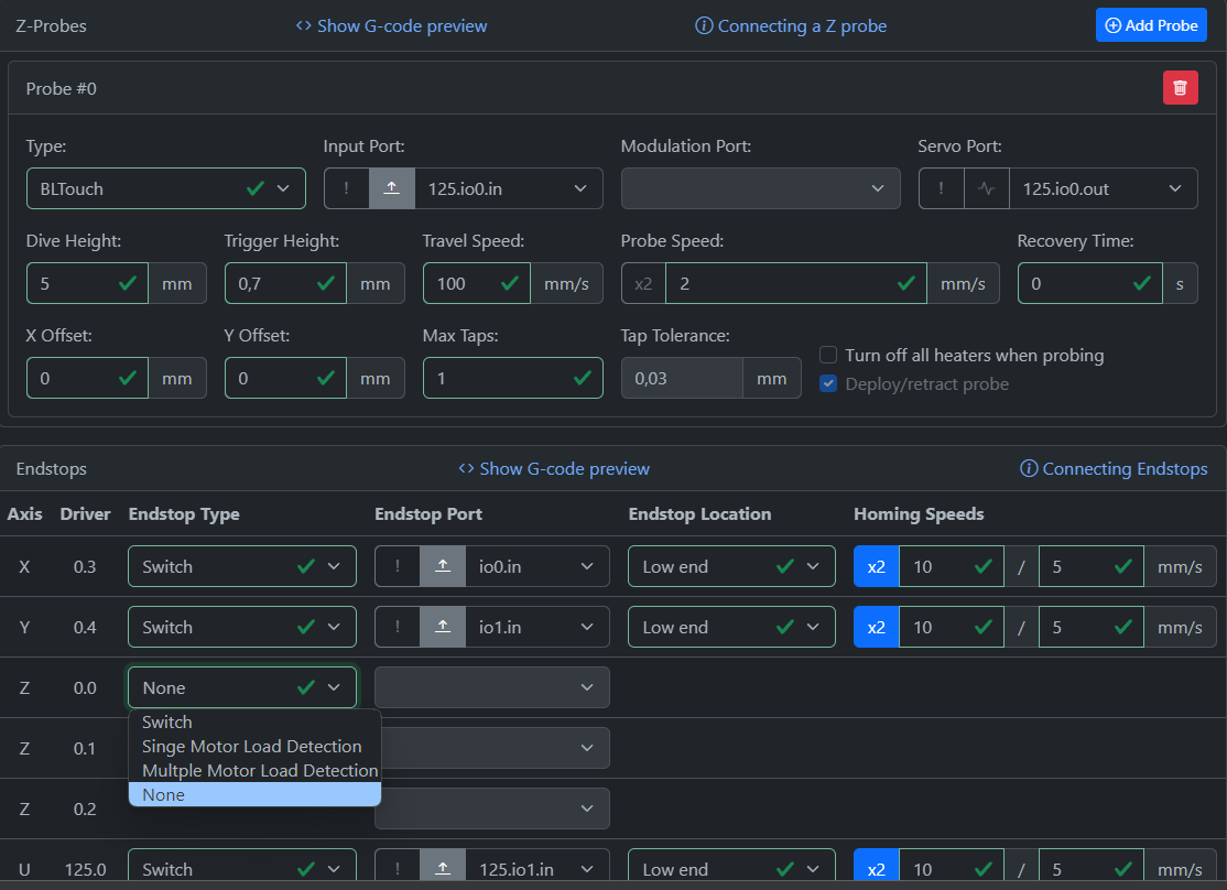
BL TOUCH isn't possible if i select like that
-
RE: New ConfigTool v3.5.0-beta.3 availableposted in Config Tool
Duet 3 Expansion 1HCL allows to add just one temp0 and not temp1