Duet3D Logo Duet3D
    • Tags
    • Documentation
    • Order
    • Register
    • Login
    1. Home
    2. Nemesis1782
    3. Best
    • Profile
    • Following 0
    • Followers 0
    • Topics 5
    • Posts 40
    • Best 3
    • Controversial 0
    • Groups 0

    Best posts made by Nemesis1782

    • 3DAVII

      Hi all,

      since I'd like to share my new printer design. It is my second printer design, I'm using a DuetWifi to drive the printer.

      The printer is being designed for my dad who has ALS. So my mom needs to be able to operate the physical aspects. This means as little as possible calibration and such. The first printer I've designed for him works well however there are a number of things I would to improve upon with this design:

      • Repeatability (This is ok on the old printer but could be mich better)
      • Size (My dad would like to print larger things)
      • Auto bed calibration (Even with bed leveling my mom is sometimes a bit to rough with the bed and it gets out of alignment)
      • The print operation needs to be at a comfortable viewing heigt from wheel chair

      So why not buy a ready build printer you say: Well cost and hobby! My dad also loves engineering so it's great working om it together.

      Details:

      • Total dimensions: +/- 700x700x1100(height)
      • Max print dimensions: 500x500x600(height), Initial design might be 400x400x600 due to me not being able to find a glass plate of 500x500 (without having it custom made and being very expensive)
      • Frame is made of 3030 and 3060 profiles which provides nice rigidity
      • CoreXY (This works well now 🙂 
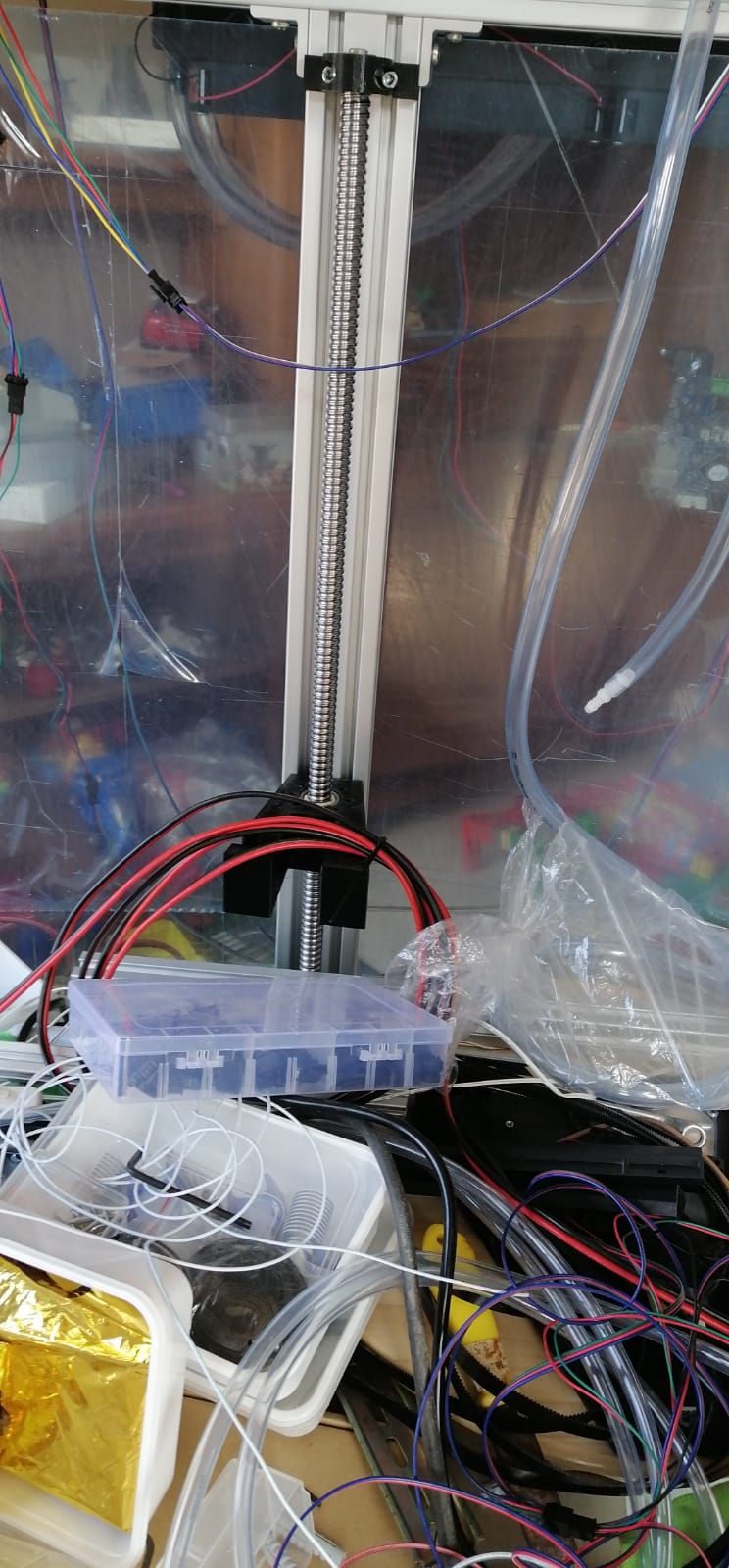
), Currently using derlin wheels however I have ordered 3 linear rails which should be much better. (Driven by 2 NEME23s)
      • 3 independently driven motors for the Z platform (Driven by 3 NEMA17s (0.9 degree), Each motor will drive a SFU1605 ballscrew of 700mm (about 650mm usable length).
      • Bed sensing: Either BLTouch (initail idea) or touch sensor using piezo
      • 1600W 230V bed heater switched by a SSRS
      • (Optional/future) Exchangeable tool carriages
        --> Tool carraige 1: A single E3D volcano
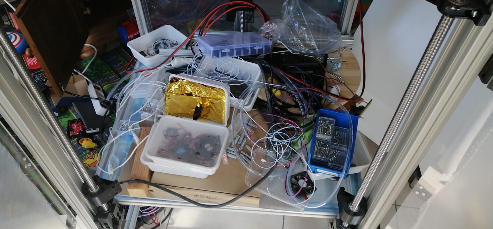
        --> Tool carraige 2: A quad E3D kraken with volcanos
      • Easily accessible bottom compartment with spool holder and filament guides so changing colour will be less of a hassle
      • Integrated UPS which can run the printer for at least 1 hour

      A number of images (work in progress do not mind the mess and yes the missus is very patient! 😛 😞
      WhatsApp Image 2020-04-12 at 12.21.58.jpeg WhatsApp Image 2020-04-12 at 12.22.14.jpeg WhatsApp Image 2020-04-12 at 12.22.30.jpeg WhatsApp Image 2020-04-12 at 12.22.46.jpeg

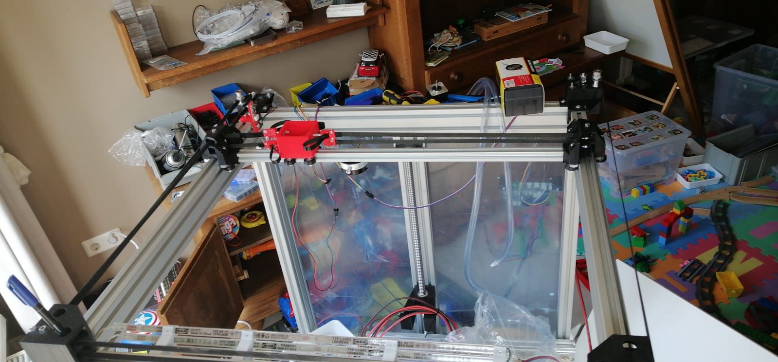
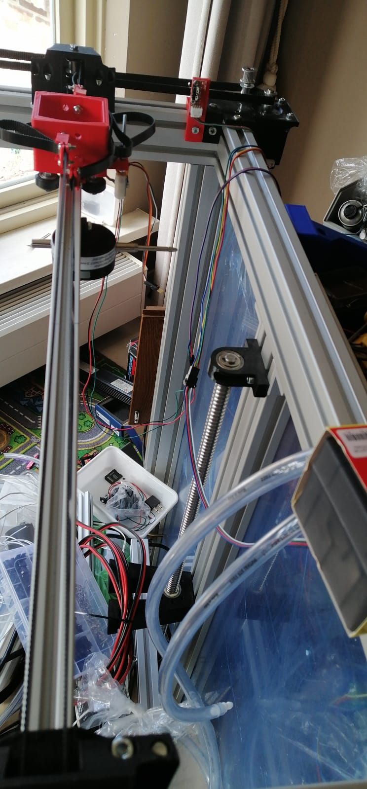
      The XY axes work however in one of the redesigns of the Y carriages I kinda forgot about the clearance for the returning belts... So near the motors there are temporary guides. Also the XY will be replaced by linear guides once they arrive.

      I'll post movies later since the site does not let me upload them.

      posted in My Duet controlled machine
      Nemesis1782undefined
      Nemesis1782
    • RE: CoreXY neither X nor Y moving

      @Phaedrux I'm sorry I tried using the configurator and it does not work correctly!

      When choosing RRF3+ I get the following config for the endstops: M574 X1 S0 P"!zstop" ; configure active-low endstop for low end on X via pin !zstop

      This does not work because S0 is no longer supported for RRF3+. It should' vv e been: M574 X1 S1 P"!zstop" ; configure active-low endstop for low end on X via pin !zstop

      Also it sets: M667 S1 ; select CoreXY mode
      Which according to documentation should be (for RRF3): M667 K1 ; select CoreXY mode

      I understand you'd like people to use the tool provided. However atm it provides more issues then it solves atm.

      posted in Duet Hardware and wiring
      Nemesis1782undefined
      Nemesis1782
    • RE: CoreXY neither X nor Y moving

      I got the motors working correct now.

      I still do have one confusing thing in the config and that has to do with assigning the drivers.
      My physical connections: X is on 0 (Normally used for Z), Y is on 1, Z is on 2 (Normally used for X) [I did this because I will be using 3 and 4 for Z as well and it makes more sense having the Zs in order]

      The working config is: M584 X2 Y1 Z0 E3:4; set drive mapping (With this config I would assume X is on the third driver however it isn't! It is on the first...)

      According to the documentation: M584: Set drive mapping
      Parameters

      Xnnn Driver number(s) for X motor(s)
      Ynnn Driver number(s) for Y motor(s)
      Znnn Driver number(s) for Z motor(s)

      So why doesn't it work when I say: M584 X0 Y1 Z2 E3:4; If I do this it treats the Z motor on driver 2 as the X, can anyone confirm if this is a bug?

      @Phaedrux The Configuration tool generates old type config when selectin RRF3+. Specific issues I had:

      • (generic issue) you select inversion when selecting the endstop for the axis and you select if it is NC or NO in the next menu. This is redundant and confusing.
      • M574 Command sets S0 when selecting a NO endswitch type. This is incompatible/depricated on RRF3
      • M667(669) Command when on RRF3 it should set M669 K1 instead of M667 S1
      posted in Duet Hardware and wiring
      Nemesis1782undefined
      Nemesis1782