@Veti does that mean you can only connect one tacho?
Posts made by Nemesis1782
-
RE: Connecting a 12V PWM FAN when using a 24V power supplyposted in Duet Hardware and wiring
-
RE: Connecting a 12V PWM FAN when using a 24V power supplyposted in Duet Hardware and wiring
@Veti which input on the duex can I use for that. The forum names a input on the duet through the extension cable only.
-
RE: Connecting a 12V PWM FAN when using a 24V power supplyposted in Duet Hardware and wiring
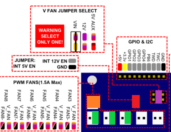
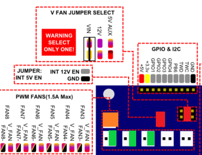
Alright, so another update couldn't leave it alone. I can confirm the Noctua runs like a charm. The above image green connections are incorrect! They need to be on FAN-
Now the only open point is the tacho, I don't really think I need it actually. What would be the benefit of connecting it?
-
RE: Connecting a 12V PWM FAN when using a 24V power supplyposted in Duet Hardware and wiring
Alright so against my better judgement I decided to test somethings out.
From what I tested the jumper makes the fan output 12V, jay! I have revised my plan of approach:

1x orange is now nothing!
1x red Jumper
1x purple 12V+ for FANs + a wire to short the two pins
3x green PWM signal
1x ground directly to ground of fans
3x tacho still not sure which inputs I can use on duex2 -
RE: Connecting a 12V PWM FAN when using a 24V power supplyposted in Duet Hardware and wiring
@dc42 Thnx for the answer. They're indeed noctuas. I say go ugly brown or go home

So just to be sure and not blow anything up:
- I have a duex2 0.8

- 2x Red jumper
- 1x Orange for 12V +/- all fans, PWM disabled (couldn't find a 12V out)
- 3x green the PWM lead for the fan
- 3x ? where would the tacho lead go? GPIO 1-3
Please let me know if that would be ok.
Also why does the documentation note only to enable 12V if you use it. Is there a risk in enabling it?
- I have a duex2 0.8
-
RE: Connecting a 12V PWM FAN when using a 24V power supplyposted in Duet Hardware and wiring
I'd say that's a fair bit of design oversight since 2 pin fans aren't meant to run under PWM and you usually end up with a lot of FAN wine.
Still since there is no limitation described in the M950 RRF3 command does that mean that it will work with that (Changing the frequency I mean)?
I'll probably just move my part cooler fan to the duex so I have three PWM fans and to the 12V thing there.
Might want to add the DUEXes PWM limitations in the specification though. Since "6 additional controlled fan outputs, also usable for driving LEDs etc. The output voltage may be switched between 5V, 12V and VIN." implies that they funtion the same as the controlled fans on the main board.
-
RE: Connecting a 12V PWM FAN when using a 24V power supplyposted in Duet Hardware and wiring
@Veti According to image they are PWM outputs. The M106 says no variable PWM which would mean changing the frequency (so you're stuck using default, which is not great ofc).
On that note the M950 does not specify any limitation. I am using RRF3 does that mean I can set the PWM frequency indendently.
-
RE: Connecting a 12V PWM FAN when using a 24V power supplyposted in Duet Hardware and wiring
@Veti Thank you for taking the time to respond.
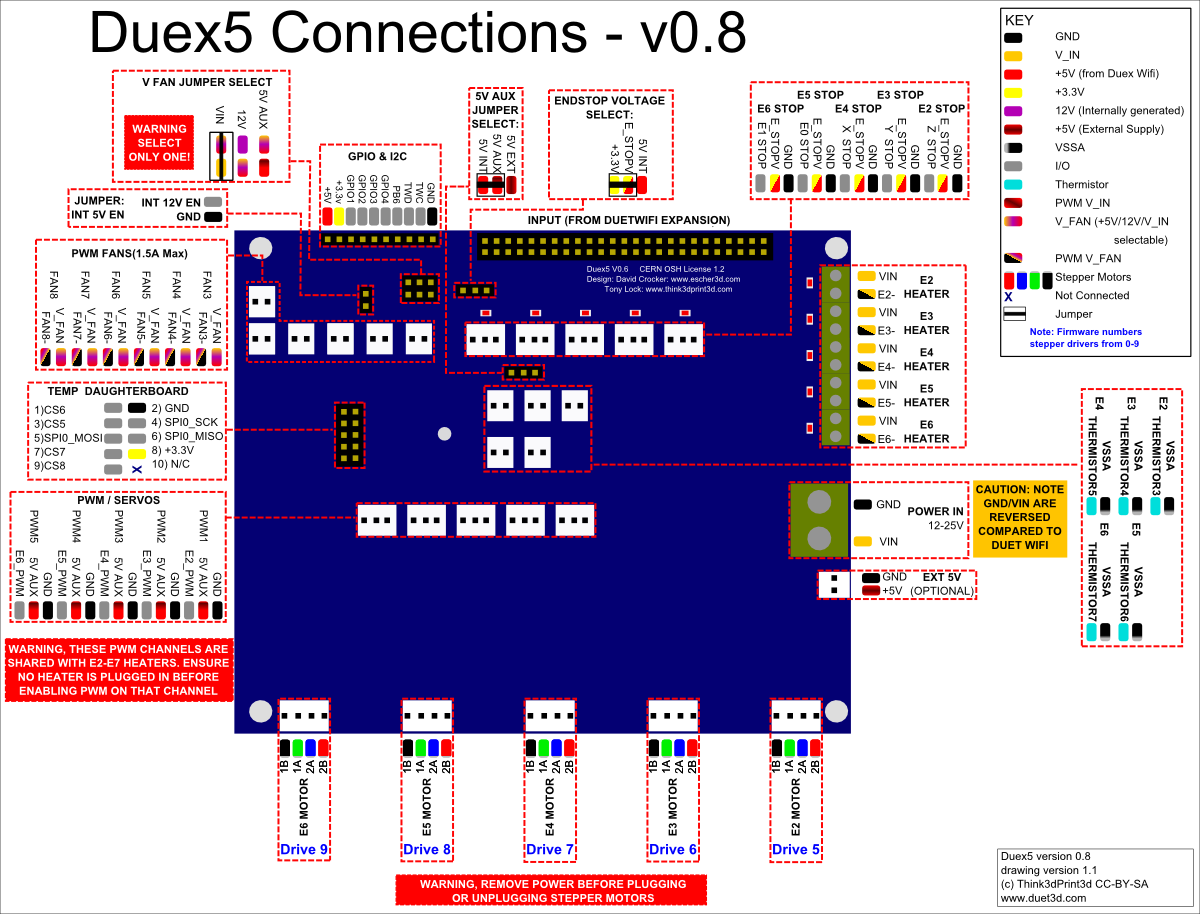
According to the documentation the Duex has a internal 12V line though. At least if I interpret it correctly.

Also the expert:
In order to use the 12V internal supply for LEDs/FANs the 12V EN jumper must be fitted. Do not fit this jumper if you are not using the 12V internal supplyIn the above referenced wiki page. Seems to suggest there is a internal 12V power supply.
The FAN's use 1W each so 3W in total which is not a whole lot.
-
Connecting a 12V PWM FAN when using a 24V power supplyposted in Duet Hardware and wiring
Hi guys,
I have a DuetWifi 2 and a Duex2 with a 24V power supply. I would like to connect 12V 4 wire PWM fans to it.
However I'm getting confused on how to wire it correctly. I have a 12V power supply lying around if needed.
I was looking through all the information and noticed:

In: https://duet3d.dozuki.com/Wiki/Duex_wiring_diagrams
Does that mean I just set the Jumper and the duex has a buck converter built in? (contrary to what is mentioned in: https://duet3d.dozuki.com/Wiki/Connecting_and_configuring_fans#Section_Using_12V_fans_when_VIN_is_24V)
-
RE: 3DTouch configuration not workingposted in General Discussion
@Phaedrux Hi, I've resolved it. It turns out one of the wires on the connector wasn't making a connection

Sorry for wasting your time and thnx for your help and patience!

Edit: So I tried going back to PWM5 since that's the one I would like to use and that is indeed not working. (well only on startup for some reason). Not a big issue thouh. However I would've liked to have the bed level sensor plugged into the most left PWM.
-
RE: 3DTouch configuration not workingposted in General Discussion
@Phaedrux said in 3DTouch configuration not working:
M280
Ah Yeah. Saw it in the documentation. I just assumed that hadn't changed for RRF3. Thnx
@HomeZ, yeah that is by design. I have 3 independent Z axis drivers and first home it to the end stop to make sure it's straight after which I'll fine tune using the bed level sensor.
-
RE: 3DTouch configuration not workingposted in General Discussion
@Phaedrux Alright so I am doing something seriously wrong. It is not behaving as I expect.
I've moved the connector to Duex PWM3 and changed the config. When I start the printer the Touch goes into error blue on blinking red.
When I then plug the Touch back into PWM5 and start the printer it does the correct startup procedure even though the config is pointing to PWM3.
config.g:
; Z-Probe
M950 S0 C"duex.pwm3" ; create servo pin 0 for BLTouch
M558 P9 C"^zprobe.in" H5 F120 T6000 ; set Z probe type to bltouch and the dive height + speeds
G31 P500 X0 Y0 Z2.5 ; set Z probe trigger value, offset and trigger height
M557 X15:215 Y15:195 S20 ; define mesh gridconfig-overide.g not changed.
Deploy and retract changed P7 to P5
-
RE: 3DTouch configuration not workingposted in General Discussion
@Phaedrux I was checking the documentation and noticed that the duex2 under version 0.8b does not support PWM 4 and 5. How do I check which version the board is?
Edit: Just checked and it is version 0.8. I'll move it to PWM3 later today.
-
RE: 3DTouch configuration not workingposted in General Discussion
@Phaedrux Hi Phaedrux, thnx for your time as always.
Yes I am using the Duex2 port pmw5. I have only included the homez.g, homeall.g is not right. Do keep in mind that I am not homing I'm just trying to get the probe itself to move. Onze that works the rest should not be a problem.
Config.g:
; Configuration file for Duet WiFi (firmware version 3)
; executed by the firmware on start-up
;
; generated by RepRapFirmware Configuration Tool v2.1.8 on Thu Apr 09 2020 12:23:53 GMT+0200 (Midden-Europese zomertijd); General preferences
G90 ; send absolute coordinates...
M83 ; ...but relative extruder moves
M550 P"3DavII" ; set printer nameM669 K1 ; select CoreXY mode
; Network
M552 S1 ; enable network
M586 P0 S1 ; enable HTTP
M586 P1 S0 ; disable FTP
M586 P2 S0 ; disable Telnet; Drives
M569 P2 S0 ; physical drive 2(X) goes backwards
M569 P1 S0 ; physical drive 1(Y) goes backwards
M569 P0 S0 ; physical drive 0 goes forwards
M569 P3 S0 ; physical drive 3 goes forwards
M569 P4 S0 ; physical drive 4 goes forwards
;M584 X2 Y1 Z0:3:4 U3 V4 P3 ; Set the drive mapping, the Duet drivers are numberred (Z)2,(Y)1,(X)0,(E1)3,(E2)4
M584 X2 Y1 Z0:3:4 ; Set the drive mapping, the Duet drivers are numberred (Z)2,(Y)1,(X)0,(E1)3,(E2)4
M350 X16 Y16 Z16:16:16 I1 ; configure microstepping with interpolation
M92 X80.00 Y80.00 Z1280.00:1280.00:1280.00 ; set steps per mm
M566 X900.00 Y900.00 Z12.00:12.00:12.00 ; set maximum instantaneous speed changes (mm/min)
M203 X6000.00 Y6000.00 Z1800.00:1800.00:1800.00 ; set maximum speeds (mm/min)
M201 X500.00 Y500.00 Z20.00:20.00:20.00 ; set accelerations (mm/s^2)
M906 X1200 Y1200 Z1700:1700:1700 I30 ; set motor currents (mA) and motor idle factor in per cent
M84 S30 ; Set idle timeout; Axis Limits
M208 X0 Y0 Z0 S1 ; set axis minima
M208 X575 Y560 Z580 S0 ; set axis maxima; Endstops
M574 X0 S1 P"zstop" ; configure active-low endstop for low end on X via pin !zstop
M574 Y0 S1 P"ystop" ; configure active-low endstop for low end on Y via pin !ystop
M574 Z1 S1 P"!xstop+!e0stop+!e1stop" ; configure active-low endstop for low end on Z via pin !xstop; Z-Probe
M950 S0 C"duex.pwm5" ; create servo pin 0 for BLTouch
M558 P9 C"^zprobe.in" H5 F120 T6000 ; set Z probe type to bltouch and the dive height + speeds
G31 P500 X0 Y0 Z2.5 ; set Z probe trigger value, offset and trigger height
M557 X15:215 Y15:195 S20 ; define mesh grid; Heaters
M308 S0 P"bedtemp" Y"thermistor" T100000 B4138 ; configure sensor 0 as thermistor on pin bedtemp
M950 H0 C"bedheat" T0 ; create bed heater output on bedheat and map it to sensor 0
M143 H0 S120 ; set temperature limit for heater 0 to 120C
M307 H0 B1 S1.00 ; enable bang-bang mode for the bed heater and set PWM limit
M140 H0 ; map heated bed to heater 0
M308 S1 P"e0temp" Y"thermistor" T100000 B4138 ; configure sensor 1 as thermistor on pin e0temp
M950 H1 C"e0heat" T1 ; create nozzle heater output on e0heat and map it to sensor 1
M143 H1 S280 ; set temperature limit for heater 1 to 280C
M307 H1 B0 S1.00 ; disable bang-bang mode for heater and set PWM limit; Fans
M950 F0 C"fan0" Q500 ; create fan 0 on pin fan0 and set its frequency
M106 P0 S0 H-1 ; set fan 0 value. Thermostatic control is turned off
M950 F1 C"fan1" Q500 ; create fan 1 on pin fan1 and set its frequency
M106 P1 S1 H1 T45 ; set fan 1 value. Thermostatic control is turned on; Tools
M563 P0 D0 H1 F0 ; define tool 0
G10 P0 X0 Y0 Z0 ; set tool 0 axis offsets
G10 P0 R0 S0 ; set initial tool 0 active and standby temperatures to 0C; Custom settings are not defined
; Miscellaneous
M501 ; load saved parameters from non-volatile memoryConfig-overide.g:
; This is a system-generated file - do not edit
; Heater model parameters
M307 H0 A90.0 C700.0 D10.0 S1.00 V0.0 B0
M307 H1 A948.0 C252.3 D6.0 S1.00 V12.2 B0
;M307 H2 A340.0 C140.0 D5.5 S1.00 V0.0 B0
;M307 H3 A340.0 C140.0 D5.5 S1.00 V0.0 B0
;M307 H4 A340.0 C140.0 D5.5 S1.00 V0.0 B0
;M307 H5 A340.0 C140.0 D5.5 S1.00 V0.0 B0
;M307 H6 A340.0 C140.0 D5.5 S1.00 V0.0 B0
;M307 H7 A340.0 C140.0 D5.5 S1.00 V0.0 B0Deployprobe.g:
M280 P7 S10 I1Retractprobe.g:
M280 P7 S90 I1Homez.g:
G91 ; relative positioning
G1 H1 Z6000 F1800 ; move Z down until the endstop is triggered
G92 Z580 ; set Z position to axis minimum (you may want to adjust this) -
RE: 3DTouch configuration not workingposted in General Discussion
@Phaedrux updated a quick test still gets me the same result. I'll double check everything later today.
M115
FIRMWARE_NAME: RepRapFirmware for Duet 2 WiFi/Ethernet FIRMWARE_VERSION: 3.1.1 ELECTRONICS: Duet WiFi 1.02 or later + DueX2 FIRMWARE_DATE: 2020-05-19b2Edit: the Z probe now shows in the web interface though

Edit2: I found a M307 for Heater 7 (PWM 5) in the config-override.g, however I do remember reading the Duet holding on to old config. How do I make sure the duet forgets about the old config? -
RE: 3DTouch configuration not workingposted in General Discussion
Erm. Yeah you're right no idea how I missed that... I fixed that right away. However it still does not work. Tomorrow I'll double check everything and report back!
The M98 is handy thnx did not know that existed.
Firmware reports: FIRMWARE_NAME: RepRapFirmware for Duet 2 WiFi/Ethernet FIRMWARE_VERSION: 3.01-RC4 ELECTRONICS: Duet WiFi 1.02 or later + DueX2 FIRMWARE_DATE: 2020-03-16b1
The config for Bedlevel is now:
; Z-Probe
M950 S0 C"duex.pwm5" ; create servo pin 0 for BLTouch
M558 P9 C"^zprobe.in" H5 F120 T6000 ; set Z probe type to bltouch and the dive height + speeds
G31 P500 X0 Y0 Z2.5 ; set Z probe trigger value, offset and trigger height
M557 X15:215 Y15:195 S20 ; define mesh gridThe M98 reported, heater warnings are as expected since I have not configured my tools yet:
6/18/2020, 8:33:16 PM M98 PCONFIG.G
HTTP is enabled on port 80
FTP is disabled
TELNET is disabled
6/18/2020, 8:33:16 PM Warning: heater 0 appears to be over-powered. If left on at full power, its temperature is predicted to reach 365C.Warning: heater 1 appears to be over-powered. If left on at full power, its temperature is predicted to reach 973C.
Error: Heater 2 not found
Error: Heater 3 not found
Error: Heater 4 not found
Error: Heater 5 not found
Error: Heater 6 not found
Error: Heater 7 not found -
RE: Invitation to share your conditional GCode scriptsposted in Gcode meta commands
Nice! This will allow me to implement tool switching without the hassle of managing multiple config files!
-
3DTouch configuration not workingposted in General Discussion
Hi all,
I'm having issues getting the 3dtouch probe to do anything on my new printer (https://forum.duet3d.com/topic/15550/3davii?_=1592476055256).
The symptoms:
When starting the printer the 3DTouch does it's usual startup routine (down,up,down,up). After which it settles in the up position with the red light continuously on (if I remember correctly that is what is supposed to happen). So all seems well, however as soon as I try to deploy the probe in any for nothing happens. I do not get a Duet error nor does the probe go into the blinking alarm state.One other weird thing I noticed is that when the duet starts it tells me in the webinterface that the probe is measuring -1000, however the whole probe indicator dissapears from the web interface within a matter of seconds.
Any help would be greatly appreciated. If any additional information is needed please let me know.
I am using a duetwifi2 and duex 2 with RRF3 and the new web gui
Connections:
The 3dTouch sensor part is connected to the duetwifi zbed sensor connector, the actuator side is connected to the Duex2 PWM5.Configuration (as generated by reprap configurator):
; Z-Probe
M307 H7 A-1 C-1 D-1 ; disable heater on PWM channel for BLTouch
M558 P9 H5 F120 T6000 ; set Z probe type to bltouch and the dive height + speeds
G31 P500 X0 Y0 Z2.5 ; set Z probe trigger value, offset and trigger height
M557 X20:200 Y20:200 S40 ; define mesh gridDeploy Probe script:
M280 P7 S10 ; deploy BLTouchRetract Probe script:
M280 P7 S90 ; retract BLTouch -
RE: Print surface for a 500x500 printbedposted in General Discussion
@jay_s_uk Hi, Thanks this is what I was looking for. Do you know where you can order replacements for the top layer?
-
Print surface for a 500x500 printbedposted in General Discussion
Hi Guys, I'm building a 500x500 printer and I would like a interchangeable print surface. I have always used glass to print on. However I now also have a Creality printer which has a magnetic print surface. I quite like the print surface although I think it's not as wear resilient as glass.
I'd like your experiences and advise. Also I cannot find the magnetic surfaces anywhere for 500x500. Can anyone point met to a affordable source?