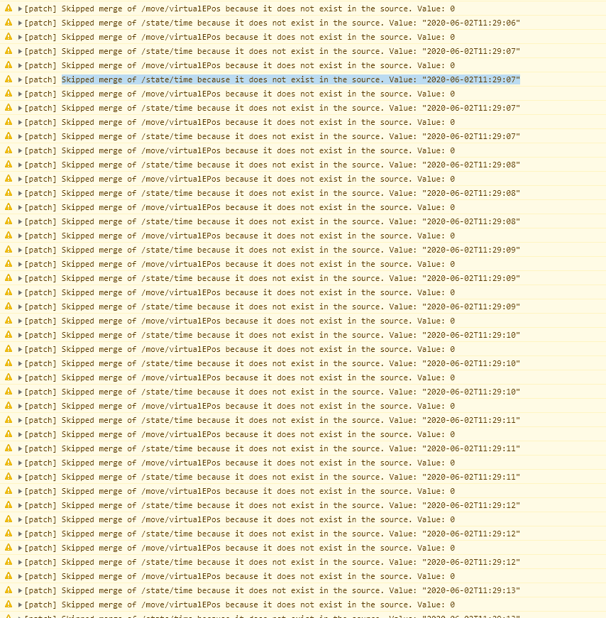
I get a massive amount of patch messages from the DWC now, is there any way I can get rid of all these messages or have something done about it in the future so it will stop posting so much?

Posts made by nickpm
-
Updated RRF3 has so many patch messagesposted in General Discussion
-
RE: Duet API return current M557 probe pointsposted in Duet Hardware and wiring
Nevermind I fixed it, was a client issue.
-
RE: Duet API return current M557 probe pointsposted in Duet Hardware and wiring
So I'm sending this now:
/rr_model?key=move.compensation.probeGrid&flags=d99vn and I'm getting a failed response that just says E

-
Duet API return current M557 probe pointsposted in Duet Hardware and wiring
Does anyone know if there is a query I can send to the machine to return the current X and Y ranges for the M557 command. So if in my config.g I have a M557 X0:100 Y0:100 S20 and then at some point I send the duet a M557 X0:50 Y0:50 S10 is that saved somewhere in the status type 1, 2, or 3 response?
-
RE: Weird Glitch with Coordinate systemsposted in Duet Hardware and wiring
@dc42 As always you're on point! Thanks I added an M208 in my home macros just in case.
-
Weird Glitch with Coordinate systemsposted in Duet Hardware and wiring
Hardware: Duet 2 Ethernet + Duex5
Firmware: RRF3.09So I keep getting this glitch when I'm using different coordinate systems. Its repeatable so I thought I'd post it here in case someone can help me out.
The Glitch:-
Home the machine
The machine homes as normal and sets the X, Y, and Z coordinates to 0,0,0 as expected. -
Run a macro to move the machine to 0,0,0 in G55
Here are the contents of the macro:G54 ;activate global coordinate system G90 ;absolute coordinates if move.axes[2].userPosition <100 G1 Z100 F1000 G55 ;activate build volume coordinate system M98 P"0:/macros/COORDINATE FUNCTIONS/WORK AREA DEFINITIONS/Build Volume Definition" ; redefine global axis limits G1 X0 Y0 F1800 ;move to origin G1 Z50 F1000 M564 H1 S1 ;Locks axesAs you can see there is an M98 that runs another file, the contents of that file are here:
M208 X130:300 Y100:290 Z-5.0:145
-
Home the machine again - Machine will home like normal except instead of replacing the X, Y, and Z coordinates with 0,0,0. The machine glitches and sets the value to 130, 180, 100. In addition, G92s no longer work with this instance of the machine no matter if you change the coordinate system. The machine will think G54 is at 130X and 180Y when it should be 0,0.
-
-
Read the contents of a file via HTTP GET request / gcodeposted in Duet Hardware and wiring
Is it possible to have a http get request return the gcode contents of a file stored on the Duet? I have an external program thats separate from the duet web control and I was hoping to be able to read the contents of files on the Duet simply through GET requests. Any help is appreciated ! RRF3 if that helps.
-
Can't get any IO to work on Duex with RRF3posted in Duet Hardware and wiring
I recently updated the firmware on my Duet2 to RRF3, I also have a Duex connected to the Duet. All of the IO on the Duet works just fine but I can't get any of the fan headers or heaters to work. I have tried putting in M950 F5 C"fan5" in the config file to initialize Fan 5 on start up but every time i do M106 P5 it returns "Error Fan number 5 not found". Can anyone help with this?
-
RE: Find out what coordinate system you're inposted in General Discussion
@dc42 I understand that the documentation is still in progress. Is there a place where I can view all of the current keys for things such as workspaceNumber. It currently isn't in the documentation, hoping it may be somewhere else so I can view all possible options I have with M409 or rr_model
-
Extended Config Responseposted in General Discussion
So I saw in Reprap firmware there was a extended config response. Can anyone tell me what the http request I use to get that response. I use this for the regular status requests. rr_status?type=XXX
-
RE: Find out what coordinate system you're inposted in General Discussion
Both, I'm transitioning into V3 right now.
-
Find out what coordinate system you're inposted in General Discussion
Hi I was using the work offset Gcodes G54 and G55, I was wondering is there some sort of JSON response that you can query the machine to find out what coordinate system you're in. Like if it is in G55 it'll tell me as opposed to being in the G54 coordinate system.
-
How to use the CAN-FD busposted in Duet Hardware and wiring
So I recently ordered a Duet 3, Expansion Board, Tool Distribution Board, and 3 Toolboard 1LCs. I have no prior knowledge of CAN-FD or CAN bus use in general. Can someone give me a quick rundown on how to communicate between the mainboard to the tool distribution board to the 3 separate toolboard 1lcs. Is there an interface on the main Duet 3 that detects if theres a tool distribution attached and then from there checks for more peripheral boards. Any help, information , or resources would be greatly appreciated.
-
RE: Trouble with Using External Stepper Motorsposted in Duet Hardware and wiring
@dc42 Yup that was it, I'm just gonna pass through the enable signals through to the stepper drivers on the Duex and set the external stepper drivers to be active low enable.
-
Trouble with Using External Stepper Motorsposted in Duet Hardware and wiring
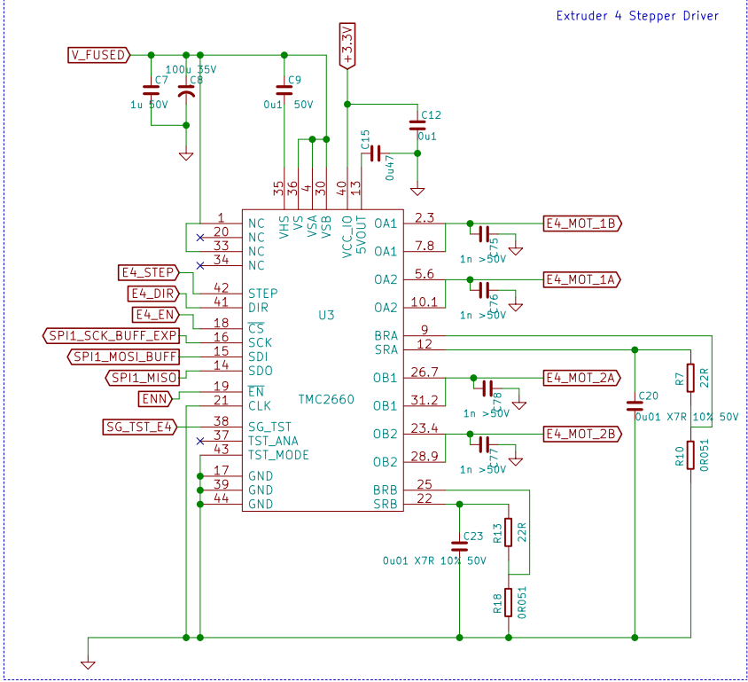
So I am using external stepper motors and am taking advantage of the signals that pass through the 50 Pin Connector. However, I designed a PCB that would only take the signals I needed and then pass the signals I do not use back into the Duex. This way I could still use the I2C on the Duex for other purposes and things like the fans and such. The problem I am running into is that the Duex will freak out if you don't send the E2_EN, E3_EN, E4_EN, E5_EN, and E6_EN back into it when I am trying to use those signals to power the Enable on my own external stepper driver. The motors turn just fine when I don't have the Duex connected, only my PCB is connected to the Duet via the 50 pin connector. Any advice on how I can get this working and keep the features of the Duex as well?
-
RE: External Stepper Motors Problemposted in Duet Hardware and wiring
One of the problems I ran into was the 2.5us pulse width was too small for good signal integrity.
-
External Stepper Motors Problemposted in Duet Hardware and wiring
I am using this stepper motor driver and stepper motor kit:
After breaking out the Duet's external stepper driver signals from the 50 pin connector I step the signal up from 0-3.3 to 0-5V and then send it through a differential line driver. This feeds directly into the stepper driver. I've gotten my motors to work, however, I have to set the pulse width to around 50microseconds at least. Also the Duet will disconnect after a few movements reporting this error from Pronterface:
[ERROR] Can't read from printer (disconnected?) (SerialException): call to ClearCommError failed
[ERROR] Can't write to printer (disconnected?) (SerialException): WriteFile failed (WindowsError(22, 'The device does not recognize the command.'))
[ERROR] Can't write to printer (disconnected?) (SerialException): WriteFile failed (WindowsError(22, 'The device does not recognize the command.'))
[ERROR] Can't write to printer (disconnected?) (SerialException): WriteFile failed (WindowsError(22, 'The device does not recognize the command.'))
[ERROR] Can't write to printer (disconnected?) (SerialException): WriteFile failed (WindowsError(22, 'The device does not recognize the command.'))
[ERROR] Disconnecting after 4 failed writes.
Disconnected.For further troubleshooting here is my config.g file:
; Configuration file for Duet WiFi (firmware version 1.21)
; executed by the firmware on start-up
;
; generated by RepRapFirmware Configuration Tool v2 on Thu Jun 20 2019 13:54:55 GMT-0500 (Central Daylight Time); General preferences
G90 ; Send absolute coordinates...
M83 ; ...but relative extruder moves; Network
M550 P"Frank" ; Set machine name
M552 S1 ; Enable network
;*** Access point is configured manually via M587
M586 P0 S1 ; Enable HTTP
M586 P1 S0 ; Disable FTP
M586 P2 S0 ; Disable Telnet; Drives
M584 X5 Y6 Z7
M569 P5 T200 S1 ; Drive 5 goes forwards
M569 P6 T200 S1
M569 P7 T200 S1M350 X16 Y16 Z16 E16 u16 V16 I1 ; Configure microstepping with interpolation
M92 X100.00 Y100.00 Z1600.00 E5040.00 u64.4 V64.4 ; Set steps per mm
M566 X900.00 Y900.00 Z12.00 E25.00 U100 V100 ; Set maximum instantaneous speed changes (mm/min)
M203 X60000.00 Y60000.00 Z300.00 E60.00 U1500 V1500 ; Set maximum speeds (mm/min)
M201 X1000.00 Y1000.00 Z100.00 E50.00 U1000 V500 ; Set accelerations (mm/s^2)
M906 X2500.00 Y1500.00 Z1500.00 E400.00 u1500 V1500 I30 ; Set motor currents (mA) and motor idle factor in per cent
M84 S30 ; Set idle timeout; Axis Limits
M208 X0 Y0 Z0 u0 S1 ; Set axis minima
M208 X255 Y310 Z200 u500 S0 ; Set axis maxima; Endstops
M574 X1 Y1 S0 ; Set active low and disabled endstops
M574 Z1 S2 ; Define Z to use Probe. Home to Min
M557 X15:215 Y15:195 S20 ; Define mesh grid
M558 P5 X0 Y0 Z1 H2 F300 T6000 ; Set Z Probe to type Switch or Digital output where Z probe connector is used. Used for z only
G31 P50 X-40.70 Y8.70 Z3.57 ; Set Z probe trigger value, offset and trigger height
M574 u0 s3; Z-Probe
;M558 P1 H5 F120 T6000 ; Set Z probe type to unmodulated and the dive height + speeds
;G31 P500 X0 Y0 Z2.5 ; Set Z probe trigger value, offset and trigger height; Heaters
M305 P0 T100000 B4138 R4700 ; Set thermistor + ADC parameters for heater 0
M143 H0 S120 ; Set temperature limit for heater 0 to 120C
M305 P1 T100000 B4138 R4700 ; Set thermistor + ADC parameters for heater 1
M143 H1 S280 ; Set temperature limit for heater 1 to 280C;Disable heater to free up PWM channel
M307 H7 A-1 C-1 D-1 ;Disable heater 7 for BLTouch; Fans
M106 P0 S0 I0 F500 H T45 ; Set fan 0 value, PWM signal inversion and frequency. Thermostatic control is turned on
M106 P1 S1 I0 F500 H1 T45 ; Set fan 1 value, PWM signal inversion and frequency. Thermostatic control is turned on; Tools
M563 P0 D0 H1 ; Define tool 0
G10 P0 X0 Y0 Z0 ; Set tool 0 axis offsets
G10 P0 R0 S0 ; Set initial tool 0 active and standby temperatures to 0CM563 P1 S"MicroDispense" D0 ; Define tool 2
;M572 D0 S0.15 ; Pressure Advance initialization
;M557 X110:180 Y55:100 S15 ; Mesh size for FR4 substrate
;M558 P0 X0 Y0 Z0 F120 T600 H2 ; Probe initialization;M200 D9.5 ; Enable Volumetric extrusion
; Automatic saving after power loss is not enabled
; Custom settings are not configured
Any insight would be greatly appreciated.
