@garyd9
That's the answer I was looking for!
I am looking at the 713maker mounts and they will fit my rig perfectly.
Now I'm off to get that Smart Effector!
Thx m8!
Posts made by nurbie
-
RE: Smart Effector usable w/o carriage set-up?posted in Smart effector for delta printers
-
Smart Effector usable w/o carriage set-up?posted in Smart effector for delta printers
Rebuilding a Rostock MaxV3 into a Duet2 WiFi machine with a DirectDrive extruder mounted at the hot end.
Need a calibration nozzle contact sensor/solution.
Recently discovered the Duet Smart Effector v1.3 (StrainEffector) pcb. Looks promising!Is the Smart Effector usable for Z touch-offs/calibration moves at the nozzle without the carriage inputs?
I see that the Duet Smart Effector involves the triangulation component with pcbs at the carriage glides but I don't think my carriages can accommodate those boards.
Not sure if the Duet Smart Effector is a waste of pcb if not employing the control arm/carriage loops?
Feedback?
-
RE: Duet 2 WiFi Dual Extruder testing w/o H1?posted in General Discussion
DOH!
I had just set that up for the clay machine!
AND,
the M302 works.
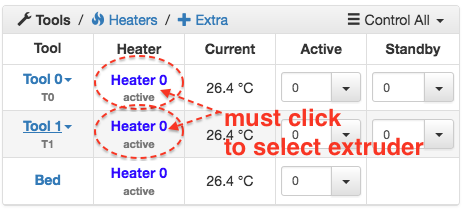
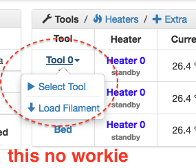
Well now, ain't life grand.One weirdness is that to select between the extruders I have to use the Heater section(?)
-
Duet 2 WiFi Dual Extruder testing w/o H1?posted in General Discussion
I want to balance my dual extruder setup(RostockV4/SMCNC) without engaging any heaters.
Duet GUI only allows extrude/retract when temps are at min 180c.
Is there something I can fudge in the config to allow me to test the steppers without having the HE come to temp? or to something less than 180c?Also, GUI only allows me to switch between the extruder steppers by clicking on the Heater ; when I go to Tool_0/1 and try to Select/Deselect the tool it has no effect. Is that normal?
My extruder config:
;extruder E0
M563 P0 D0 H1 ; Hotend (T0), drive (E0), heater (H1)
G10 P0 S0 R0 ; Hotend operating and standby temperatures;extruder E1
M563 P1 D1 H1 ; Hotend (T1), drive (E1), heater (H1)
G10 P1 S0 R0 ; Hotend (1) operating and standby temperatures -
RE: Stepper temp sensing for Duet2 WiFi PWM fan?posted in Duet Hardware and wiring
I must need sleep; no gcode needed when, CLEARLY, the fan comes on when the machine starts, and then has no reason to turn off because the thing is extruding until the model is printed.
At which time it will get shut off when I turn the machine off.Sensor version will be interesting.
I found some LM35 sensor boards online that are remarkably low-priced, so if I go the temp sensing way it's looking pretty simple, as I just discovered the E0 / E1 temp connections on the Duet! Awesome.
Plug-n-play??
We'll shall see about thatin later episodes
-
RE: Stepper temp sensing for Duet2 WiFi PWM fan?posted in Duet Hardware and wiring
Does anyone know how to set the config to turn on a fan when the E0 / E1 gets activated?
-
RE: Stepper temp sensing for Duet2 WiFi PWM fan?posted in Duet Hardware and wiring
It may not need it, but the guys that engineered the setup added it, SO,
I'm guessing it needs it.
Now, that said, I just swapped the stepper for one with about 1.5x the torque capability...might solve all(?).
Stepper is driving a (reverse archimedes-action )screw within the body and pushing clay out the nozzle, not melted plastic.
Probably the reason?Haven't had the chance to crank it all up yet!
-
Stepper temp sensing for Duet2 WiFi PWM fan?posted in Duet Hardware and wiring
I've got a stepper riding on my Rostock Delta effector as an extruder. Homes and deck calibrates superbly.
Sporty fan + shroud mounts on top of the stepper and runs the wire bundle to the Duet above.
Currently running the fan from PWM2 on the Duet, with no variable control for when it runs(on all the time right now).
config slice:
M106 P0 H-1 ; PART-DRYING fan
M106 P1 T30 H100:101:102:103 S127 ; DUET CPU fan
M106 P2 S100 ; LDM fanM563 P0 D1 S"LDM_01" ; create a named tool using extruder drive 0
//This is the motor I'd like to trigger the fan coming on for//IDEAL choice would be to have the gcode drive the fan whenever the E0 or E1(whichever is driving the extruder stepper) is energized/running)
Thing starts to print, fans stays on, no sensor required.
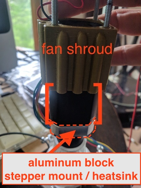
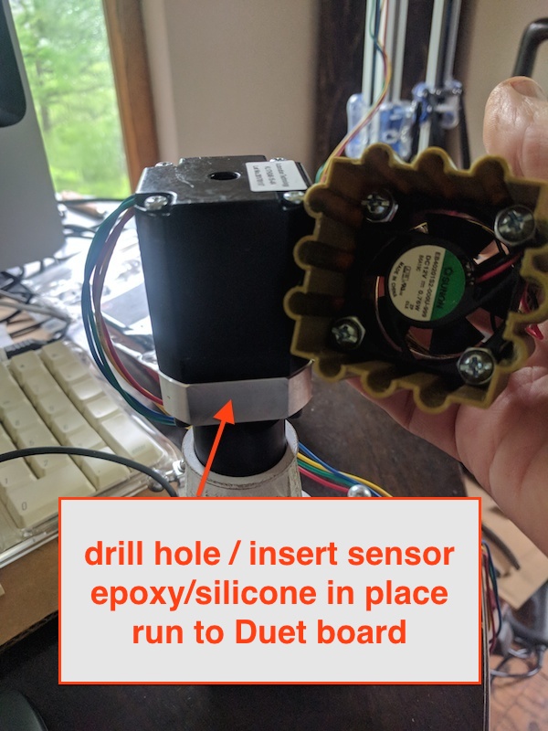
Second choice is to mount a thermistor?/sensor (LM35?) in the mount/heatsink and wire it to the Duet.
Can I even do that without a board to manage the signal?What d'y'allses think, ehhh?
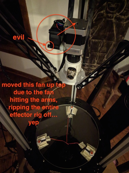
-
RE: DUET 2 WiFi FSR no workie - config?posted in General Discussion
Yes, the wiring diagrams I saw clearly are the first layout.
Then I found one that had some color-blindness going on,
but got me there:It states:
Grey is the Signal, red is 3v3 and black is ground
(this is not my board/trinket)
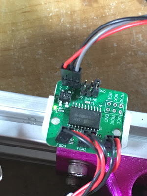
I was convinced 'gray'(my red) is 3.3v, because the board was getting power and working/sensing/lighting up the correct LEDs.
Right?
I just stared at my config and thought,"what could possibly go wrong? I might fry a $7 (USD) part, but ...
MAGIC COULD HAPPEN"
I mean,
SCIENCE COULD HAPPEN!


and there was much rejoicing
-
RE: DUET 2 WiFi FSR no workie - config?posted in General Discussion
SOLVED

That is, on a Rostock Delta Max V3 running JohnSl FSR kit
-
RE: DUET WiFi E0 / E1 no workie - config?posted in General Discussion
YES! Gracci dc42!
M563 P0 D0 S"LDM_01" did the trick! now testable via GUI.
Should there be a Duet LED (proximate to the connector like XYZs) showing that the E0 is energized?M302's not sure if they made any changes but added them as backup.
NOW, on the getting the FSRs recognized by the Duet . . . (that's another forum post)
M563 P0 D0 S"LDM_01" ; create a named tool using extruder drive 0
M558 P5 X0 Y0 Z0 H15 F200 I1 ; FSR Settings
G31 P500 X0 Y0 Z-0.3 ; Probe trigger value and offsets
M270 I1 P1 S0.05 ; Enabled Probe doubletap w/ 0.05mm tolerance
M557 R140 S30 ; default bed mapping
M501 ; Load saved config values
T0 ; Select Tool 0M302 ; Report current state
M302 P0 ; Allow cold extrusion
M375 ; Load height map -
RE: DUET WiFi E0 / E1 no workie - config?posted in General Discussion
How can I test the E0 / E1 steppers to know that they are working /wired correctly?
How do I control them through the GUI/terminal?
Any tests/ideas?
-
RE: DUET WiFi E0 / E1 no workie - config?posted in General Discussion
XYZ steppers appear to be energised and have LEDs on.
That, and I know they work since I can control them through the GUI.Does the LED for E0 / E1 only light up if extrusion is called for in gcode?
How can I test the E0 / E1 steppers to know that they are working /wired correctly?
Is there some gcode I can load to test them? -
RE: DUET WiFi E0 / E1 no workie - config?posted in General Discussion
Yes, this machine will be doing cold extrusion exclusively.
Where would I enter the M302 value? -
DUET 2 WiFi FSR no workie - config?posted in General Discussion
My FSR trinket isn't talking to the DUET2 WiFi.
JohnSL board and FSRs all signal properly;using my finger lightly on the build plate the trinket red LEDs light up correctly/individually/averaged depending on pressure location.
Should I see anything blinking on the DUET board, or see the Z-probe GUI change?
Z-probe GUI always reads 0Wiring to the Z-probe connector is correct according to DUET Z-probe wiring diagram.
Using the OEM GreenBlackRed assignments for the JohnSL
FSR board is wired to Duet z-probe as:
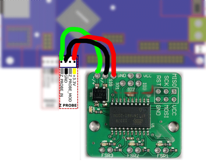

I've tried running g30 and tapping the deck, and switching the wiring between GND and IN. Red wire has remained 3.3v(?)
The JohnSL trinket lights up as it should, hotspots/averaged, but that signal doesn't halt the g30 as it should so I shut the thing down and try again.
Ran g32
effector tracked down to bed,
moved to Z periphery,
slowly lowered to trigger FSR - FSR showed contact(lit up)
crashed build plate until I emergency aborted(but not before the effector was tweaking arms and effector plate joints ...)
FSRs just aren't talking to DUET.
nothing registers in GUI; shouldn't I be seeing a response here(Z-probe) when manually/other triggering the FSRs?: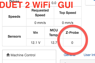
Not sure what else to do
latest config: (FSR@bottom)\\\
M550 PODWOOD_CLAY_01 ; Printer name
M555 P2 ; Gcode Output Type
M552 S1 ; Enable Wifi
G21 ; Work in millimeters
G90 ; Send absolute coordinatesM569 P0 S0 ; Drive 0 goes forwards (X)
M569 P1 S0 ; Drive 1 goes forwards (Y)
M569 P2 S0 ; Drive 2 goes forwards (Z)
M569 P3 S0 ; Drive 3 goes forwards (E0)
M569 P4 S0 ; Drive 4 goes forwards (E1)M574 X2 Y2 Z2 S1 ; set endstop configuration (all endstops at high end, active high)
M665 R144 L291.06 B135 H375 X0 Y0 Z0 ; delta radius, diagonal rod length, printable radius and homed height
; Y X Z are tower angle offsets
M666 X0 Y0 Z0 ; endstop offsets in mmM350 X16 Y16 Z16 E16:16 I1 ; Set 16x microstepping w/ Interpolation
M92 X80 Y80 Z80 ; Set axis steps/mm
M92 E400.0:400.0 ; Set extruder steps/mmM906 X1200 Y1200 Z1200 E1200:1200 I50 ; Set motor currents (mA) and idle current %
M201 X4200 Y4200 Z4200 E5000 ; Accelerations (mm/s^2)
M203 X15000 Y15000 Z15000 E15000 ; Maximum speeds (mm/min)
M566 X2000 Y2000 Z2000 E2000 ; Maximum instant speed changes mm/minuteM106 P0 H-1 ; PART-DRYING FAN
M106 P1 S1 H-1 ; DUET CPU fan
M106 P2 T25 S100 ; LDM fanM563 P0 D0 S"LDM_01" ; create a named tool using extruder drive 0
M558 P5 X0 Y0 Z0 H15 F200 I1 ; FSR Settings
G31 P500 X0 Y0 Z-0.3 ; Probe trigger value and offsets
M270 I1 P1 S0.05 ; Enabled Probe doubletap w/ 0.05mm tolerance
M557 R140 S30 ; default bed mapping
M501 ; Load saved config values
T0 ; Select Tool 0M302 ; Report current state
M302 P0 ; Allow cold extrusion
M375 ; Load height map\\\\
I'm thinking there's some config like M581: Configure external trigger or M585: Probe Tool (?) that I need to mess with to have the Z-probe get initialized?
What does this do?
M270 I1 P1 S0.05 ; Enabled Probe doubletap w/ 0.05mm tolerance -
DUET WiFi E0 / E1 no workie - config?posted in General Discussion
RMAX V3
DUET WiFi 2.02 firmwareXYZ + endstops/homing all work perfectly
PREFACE, I did fudge with the config, adjusted steps to 80, and deleted anything heated/thermistors, bed, and hot-end.
Not extruding anything heated.The BIG DEALio (fail):
The extruder stepper itself is connected to the E0 section, but it doesn't energise/show an LED, and the DUET WiFi interface has the Extruder controls grayed out and inaccessible:


I have tried 2x other steppers and none of them seem to respond/show a connection to the Duet in either E0 or E1 positions.E0 and E1 steppers don't energize/connect
wiring is correct/tried multiple steppers on both E0 and E1
It must be my n00b-modified config.g
Can you see what I'm missing? (config below)M550 PODWOOD_CLAY_01 ; Printer name
M555 P2 ; Gcode Output Type
M552 S1 ; Enable Wifi
G21 ; Work in millimeters
G90 ; Send absolute coordinatesM569 P0 S0 ; Drive 0 goes forwards (X)
M569 P1 S0 ; Drive 1 goes forwards (Y)
M569 P2 S0 ; Drive 2 goes forwards (Z)
M569 P3 S0 ; Drive 3 goes forwards (E0)
M569 P4 S0 ; Drive 4 goes forwards (E1)M574 X2 Y2 Z2 S1 ; set endstop configuration (all endstops at high end, active high)
M665 R144 L291.06 B135 H375 X0 Y0 Z0 ; delta radius, diagonal rod length, printable radius and homed height
; Y X Z are tower angle offsets
M666 X0 Y0 Z0 ; endstop offsets in mmM350 X16 Y16 Z16 E16:16 I1 ; Set 16x microstepping w/ Interpolation
M92 X80 Y80 Z80 ; Set axis steps/mm
M92 E400.0:400.0 ; Set extruder steps/mmM906 X1200 Y1200 Z1200 E1200:1200 I50 ; Set motor currents (mA) and idle current %
M201 X4200 Y4200 Z4200 E5000 ; Accelerations (mm/s^2)
M203 X15000 Y15000 Z15000 E15000 ; Maximum speeds (mm/min)
M566 X2000 Y2000 Z2000 E2000 ; Maximum instant speed changes mm/minuteM106 P0 H-1 ; Part Cooling Fan
M106 P1 S0.5 H-1 ; Case fan
M106 P2 T50 S0.7 H1 ; Heat sink fanM558 P5 I1 X0 Y0 Z0 H15 F200 ; FSR Settings
G31 P500 X0 Y0 Z-0.3 ; Probe trigger value and offsets
M270 I1 P1 S0.05 ; Enabled Probe doubletap w/ 0.05mm tolerance
M557 R140 S30 ; default bed mapping
M501 ; Load saved config values
T0 ; Select Tool 0M302 ; COLD EXTRUSION
M375 ; Load height map////////////
My JohnSL FSR board doesn't seem to respond at the DUET board either; it's properly sensing and the wiring is correct per the DUET2 instructions/wiring diagram...
