@fcwilt I was curious about binding two or more macros to a single button. One to execute if the button is tapped and a different one if it is held down.
Sam
@fcwilt I was curious about binding two or more macros to a single button. One to execute if the button is tapped and a different one if it is held down.
Sam
@jay_s_uk M581 appears to be used to detect going from low to high or high to low for some trigger, how can I use that to map it to different actions based off of if it goes high low high quickly or just from low to high and stays that way?
@jay_s_uk Thank you for your help. Is the duet IO pins capable of triggering different events if it receives a pulse of being turned on/off versus a stable on or off signal?
@jay_s_uk Thank you for your reply. Do I understand this correctly? As long as each fan draws less than the 2A switching load max then it doesn't matter where the +24V comes from, so I can use out1 to power the heater and the two fans.
I'm not looking to directly replicate the stealth burner setup. I like to build different toolheads for my custom built 3D printer which is why I built a tool hot swap setup. My printer is small and my duet has many available pins on it so I'd rather just use the capabilities of my mainboard then spend $45+ dollars on a Duet tool board for each new tool I build.
My idea has all of the convivences of a CAN tool board without the extra cost. My Prusa Mk4S with the Prusa Loveboard has a very similar setup to my idea for the same reasons and I wanted to implement it in the printer that I built. By making it myself it can be much more compact since it doesn't need any driver chips on it as well. Also truthfully, its a fun project for me to learn KiCAD.
What is the mosfet switching capacity of the fan GND pins? Is it rated to handle the current that heater 1 outputs? If it is, would that be the simpliest way to simplify the wires and feed +24V to heater 1 and both of my fans?
@jay_s_uk Why is taking the +24V from a main line rather than from the dedicated +24V pin for each component run the risk of blowing the mosfet? What is the current limit on the mosfets and is my wire simplification idea worth it if I run the risk of damaging the board? What kind of precautions could I take to just use the +24V from heater 1?
Also, I probably should have mentioned this earlier but I was inspired by this: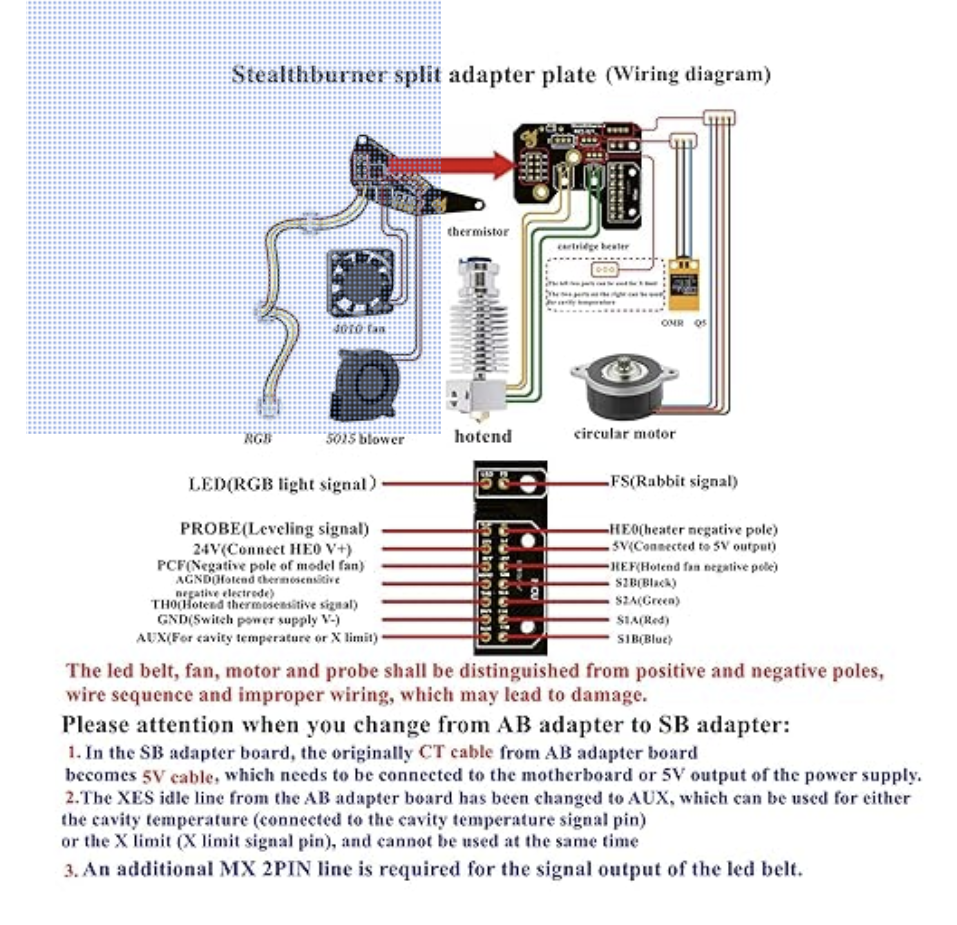
Edit: link to part here
On this stealthburner part it appears that they hae done some sort of wire simplification since it looks like they have more things connected to the board then wires running back to the main baord and I wanted to do something similar.
Edit: The stealthburner part has pins labeled +24V (connected to heater 0 V+), +5V and GND which appear to have multiple things connected to it. Hence where my idea to simply the wiring came from.
@jay_s_uk Ok thank you for your help. Is using out1's 24V line the best place to draw the 24V from to power everything? Also, would using a separate ribbon cable be best for the accelerometer or would that still have interference problems if that ribbon cable is in the same wiring loom as the main ribbon cable?
@jay_s_uk So am I safe to connect everything that uses +24V together (hot end heater and two fans) and then just run each individual ground wire back? Is this unadvisable for any/all of the components I wish to connect to my board? Also does the thermistor run on +3.3V and can its +V wire be combined with that of my force sensitive resistor that uses an io port?
Thank you for your help - Sam
@fcwilt Mine is similar. However it rather than an electrical connection between the master plate and the tool plate mine is purely mechanical and I plan to just unplug the single ribbon cable from my PCB when I switch tools. Yes, I have taken into account the necessary wire gauges for the heaters.
Sam
@fcwilt Yes I have considered those boards. I have a few reasons for wanting to make such a board. First, I have designed a manual tool swap mechanism that lets me unclip the tool from the gantry and swap in a different tool. (This lets me make a custom extruders and rapidly switch between them). Secondly, it is significantly more convenient and easy to just plug in a new fan if one breaks to my board then to pull out the old cable and run the new cable all the way back to the mainboard. Third, it means I can make the wiring harness much neater and smaller because I can run a single ribbon cable from the mainboard to the tool instead of needing to run like 18 individual wires back to the mainboard. Fourth, my design will cost only a few dollars rather than the $40+ than the duet tool board would cost me.
Sam
I am looking to design a toolhead breakout board very similar to the prusa loveboard. I want to run all the hot end, io, fan, ect wires to this breakout board I am designing and then have each of the individual components, ie fans/ hot end plug into my board.
How are fans/ heaters/ io ports, ect. controlled exactly? Are the V+ pins turned on and off or the V- pins? Since many of the compents use 24V and all need ground can the number of wires I run to the breakout board be simplified? What I am curious to know is if for example all components are controlled by turning on the V+ pin can I connect the ground pins of all of my components on the breakout board together and just run one ground pin back to the duet? Or visa versa with +24V?
I am using a duet mini 5+
Looking to connect to my custom breakout board:
Thank you for your help and insight.
-Sam
I am looking to use a pressure sensor within my hot end assembly so I can level the bed and calculate nozzle offset without the need of a separate probe. I have seen a few different DIY videos on the internet however they all seem to leave out some important details. This pressure sensor seems like it could be a good fit due to its size and shape. However I am unsure as to how I would wire it since I think I need a separate board to turn its analog signal into a digital one. I am looking to connect this to my duet 3 mini 5+. Would this be a good pressure sensor to use and how would I actually wire it to my board?
There is also this one which seems to come with the board it needs. However this one is much larger and also has output wires labeled OT and SCK which don't seem to correlate with the labels of the duet mini IO pin names.
Thank you for you help and if I overlooked a much easier way to do this please let me know.
Sam
@Phaedrux On the LCD of printers that run marlin there is an option for mixing hot ends to create a gradient at a specific z range. It can be seen in this teaching tech video at 9:45. I was wondering if this function existed in the DWC and if could also be done using gcode.
Thanks,
Sam
@Garth_42 Thank you, I will try out your first idea.
Does the firmware or the DWC have a method to vary the mix ratio over a specified z distance like in Marlin?
I have built a core xy tool changer that currently has 3 tools. The first two are standard nozzles however the third is a 2 in 1 out mixing nozzle. I have a few questions about how to configure it. I took the suggestions made in this post to define the mixing nozzle as 3 separate tools. (100% of one color, 100% of the second color and 50% of each). Since my printer is a tool changer I was wondering what is the best way to handle the tpre/tpost/tfree files since tools 2, 3 and 4 are all the same extruder setup. Is there an easy way for the firmware to recognize if the any of those three tools is needed to just pick up the mixing assembly? Is there some way to have like tool 2.0, 2.1, 2.2? (I do plan on adding even more tools later on as well) Secondly, I know in Marlin on the LCD you can set the mix ratio to change automatically over a set Z distance, does this functionality exist in RRF?
Here is my current config.g file
; Configuration file for RepRapFirmware on Duet 3 Main Board 6HC
; executed by the firmware on start-up
;
; generated by RepRapFirmware Configuration Tool v3.5.0-rc.3 on Fri Mar 15 2024 11:41:50 GMT-0400 (Eastern Daylight Time)

; General
M550 P"Duet 3" ; set hostname

; Accessories
M575 P1 S0 B57600 ; configure PanelDue support

; Network
M551 P"Knights24" ; set machine password
M552 P0.0.0.0 S1 ; configure Ethernet adapter
M586 P0 S1 ; configure HTTP

; Smart Drivers
M569 P0.0 S1 D2 ; driver 0.0 goes forwards (X axis)
M915 P0.0 S1 ; set StallGuard threshold
M569 P0.1 S0 D2 ; driver 0.1 goes backwards (Y axis)
M915 P0.1 S1 ; set StallGuard threshold
M569 P0.2 S0 D2 ; driver 0.2 goes backwards (Z axis)
M915 P0.2 S1 ; set StallGuard threshold
M569 P0.3 S0 D2 ; driver 0.3 goes backwards (Z axis)
M915 P0.3 S1 ; set StallGuard threshold
M569 P0.4 S1 D2 ; driver 0.4 goes forwards (U axis)
M915 P0.4 S3 ; set StallGuard threshold
; was 2
M569 P0.5 S1 D2 ; driver 0.5 goes forwards (extruder 0)
M569 P1.0 S1 D2 ; driver 0.5 goes forwards (extruder 1)

; Motor Idle Current Reduction
M906 I10 ; set motor current idle factor
M84 S10 ; set motor current idle timeout

; Axes
M584 X0.0 Y0.1 Z0.2:0.3 U0.4 ; set axis mapping
M350 U16 I0 ; configure microstepping without interpolation
M350 X16 Y16 Z16 I1 ; configure microstepping with interpolation
M906 X900 Y900 Z900 U400 ; set axis driver currents
M92 X160 Y160 Z400 U200 ; configure steps per mm
M208 X0:265 Y0:325 Z0:300 U0:150 ; set minimum and maximum axis limits
M566 X450 Y450 Z20 U2 ; set maximum instantaneous speed changes (mm/min) ; u was 30
M203 X9000 Y9000 Z180 U5000 ; set maximum speeds (mm/min)
M201 X350 Y350 Z20 U500 ; set accelerations (mm/s^2)

; Extruders
M584 E0.5:1.0:1.1:1.2; set extruder mapping
M350 E16:16:16:16 I1 ; configure microstepping with interpolation
M906 E1000:900:900:900 ; set extruder driver currents
M92 E420:873.08:873.08:873.08 ; configure steps per mm
M566 E120:120:120:120 ; set maximum instantaneous speed changes (mm/min)
M203 E3600:3600:3600:3600 ; set maximum speeds (mm/min)
M201 E250:250:250:250 ; set accelerations (mm/s^2)

; Kinematics
M669 K1 ; configure CoreXY kinematics

; Probes
M558 K0 P9 C"io4.in" H5 F120 T6000 ; configure BLTouch probe via slot #0
G31 P500 X4 Y-70 Z0.7 ; set Z probe trigger value, offset and trigger height ; p was 500
M950 S0 C"io4.out" ; create servo #0 for BLtouch

; Endstops
M574 X1 S3 ; configure X axis endstop
M574 Y1 S3 ; configure Y axis endstop
M574 Z1 S2 ; configure Z axis endstop
M574 U1 S3 ; configure U axis endstop

; Mesh Bed Compensation
M557 X15:245 Y20:215 S40 ; probe from X=10 to 245, Y=10 to 245mm with a mesh spacing of 40mm

; Sensors
M308 S0 P"temp0" Y"thermistor" A"Heated Bed" T100000 B4725 C7.06e-8 ; configure sensor #0
M308 S1 P"temp1" Y"thermistor" A"Hemera" T100000 B4725 C7.06e-8    ; configure sensor #1
M308 S2 P"1.temp0" Y"thermistor" A"Bowden" T100000 B4725 C7.06e-8  ; configure sensor #2
M308 S3 P"1.temp1" Y"thermistor" A"Mixing" T100000 B4725 C7.06e-8  ; configure sensor #3

M915 X Y S1 R3 F1 ; stall detection paramaters

; Heaters
M950 H0 C"out0" T0 ; create heater #0
M143 H0 P0 T0 C0 S140 A0 ; configure heater monitor #0 for heater #0
M307 H0 R0.401 K0.333:0.000 D13.12 E1.35 S1.00 B0 ; configure model of heater #0
M950 H1 C"out1" T1 ; create heater #1
M143 H1 P0 T1 C0 S300 A0 ; configure heater monitor #0 for heater #1
M307 H1 R1.804 K0.293:0.000 D9.68 E1.35 S1.00 B0 V24.1; configure model of heater #1

M950 H2 C"1.out1" T2 ; create heater #2
M143 H2 P0 T2 C0 S285 A0 ; configure heater monitor #0 for heater #2
M307 H2 R2.138 K0.330:0.159 D5.61 E1.35 S1.00 B0 V24.4; configure model of heater #2

M950 H3 C"1.out2" T3 ; create heater #3
M143 H3 P0 T3 C0 S245 A0 ; configure heater monitor #0 for heater #3
M307 H3 R2.138 K0.330:0.159 D5.61 E1.35 S1.00 B0 V24.4; configure model of heater #3

; Heated beds
M140 P0 H0 ; configure heated bed #0

; Fans
M950 F0 C"out5" ; create fan #0
M106 P0 S0 L0 X1 B0.1 ; configure fan #0
M950 F1 C"out4" ; create fan #1
M106 P1 S0 B0.1 H1 T45 ; configure fan #1

M950 F2 C"1.out3"; create fan #2
M106 P2 S0 L0 X1 B0.1 X.4 ; configure fan #2
M950 F3 C"1.out4"; create fan #3
M106 P3 S0 B0.1 H2 T45 X1 ; configure fan #3

;M950 F4 C"out7"; create fan #4
;M106 P4 S0 L0 X1 B0.1 X.4 ; configure fan #4
M950 F5 C"1.out6"; create fan #5
M106 P5 S0 B0.1 H3 T45 X1 ; configure fan #5

; Tools
M563 P0 D0 H1 F0 S"Hemera"; create tool #0
G10 P0 Z-4.55 ; set custom offsets for tool #0
M568 P0 R0 S0 ; set initial tool #0

M563 P1 D1 H2 F2 S"Bowden"; create tool #1
M568 P1 R0 S0 ; set initial tool #1
M572 D1 S0.55 ; set presure advance for tool #1
;M207 P1 S20 R20 F2400 ; set retraction paramaters for when tool is disabled

M563 P2 D2:3 H3 S"Mixing1" ;F4; create tool #2
M568 P2 R0 S0 ; set initial tool #2
M572 D2:3 S0.55 ; set presure advance for tool #2
M567 P2 E1.0:0.0 ; set tool #2 mixing value

M563 P3 D2:3 H3 S"Mixing2" ;F4; create tool #3
M568 P3 R0 S0 ; set initial tool #3
M567 P3 E0.0:1.0 ; set tool #3 mixing value

M563 P4 D2:3 H3 S"Mixing3" ;F4; create tool #4
M568 P4 R0 S0 ; set initial tool #4
M567 P4 E0.5:0.5 ; set tool #4 mixing value
Thank you for your time
Sam
@Phaedrux The white wire must have came loose at the start of the day and then I must've replugged it into the wrong pin spot. I believe I connected the BL touch's white wire into +3.3 V instead of IN when I was checking the wires. I noticed this, fixed it and it works fine now. thankfully it didn't break anything.
I have had the basics of my custom core xy tool changer 3D printer working for months and now it fails to home the Z axis and reports that the probe was already triggered at the start of the probing move. I haven't made any changes to this part of the machine in a very long time. I triple checked my wiring and did find what was potently a loose wire but upon changing its connector and replugging it back in it still gave me the same error. When I try homeall.g the errors are :
G28 Z
Error: M280: Probe already triggered at start of probing move
Error: M915: Probe already triggered at start of probing move
The probe also does not deploy at all like it should during the homeall.g file. Manually adding M401 into the homall.g file did deploy the probe but still gave the same error.
If I try M401 to deploy the probe the probe does deploy and the BL touch light does turn off. When I tap the probe with my finger the BL touch does turn red, although it doesn't show up in the DWC. (it is my understanding that this is normal though since its very fast). When I push the probe up with my finger I do also feel it pushing back.
Running M401 and the G30 to probe the bed gives me the error:
Error: M280: Probe already triggered at start of probing move
or the error:
Error: G30: Probe already triggered at start of probing move
On the startup of my machine the BL touch does do the correct deploy, retract, deploy, retract startup sequence as well.
Is it possible my Bl touch is broken? Any help would be appreciated. Below are some of my system files.
config.g
; Configuration file for RepRapFirmware on Duet 3 Main Board 6HC
; executed by the firmware on start-up
;
; generated by RepRapFirmware Configuration Tool v3.5.0-rc.3 on Fri Mar 15 2024 11:41:50 GMT-0400 (Eastern Daylight Time)

; General
M550 P"Duet 3" ; set hostname

; Accessories
M575 P1 S0 B57600 ; configure PanelDue support

; Network
M551 P"Knights24" ; set machine password
M552 P0.0.0.0 S1 ; configure Ethernet adapter
M586 P0 S1 ; configure HTTP

; Smart Drivers
M569 P0.0 S1 D2 ; driver 0.0 goes forwards (X axis)
M915 P0.0 S1 ; set StallGuard threshold
M569 P0.1 S0 D2 ; driver 0.1 goes backwards (Y axis)
M915 P0.1 S1 ; set StallGuard threshold
M569 P0.2 S0 D2 ; driver 0.2 goes backwards (Z axis)
M915 P0.2 S1 ; set StallGuard threshold
M569 P0.3 S0 D2 ; driver 0.3 goes backwards (Z axis)
M915 P0.3 S1 ; set StallGuard threshold
M569 P0.4 S1 D2 ; driver 0.4 goes forwards (U axis)
M915 P0.4 S3 ; set StallGuard threshold
; was 2
M569 P0.5 S1 D2 ; driver 0.5 goes forwards (extruder 0)
M569 P1.0 S1 D2 ; driver 0.5 goes forwards (extruder 1)

; Motor Idle Current Reduction
M906 I10 ; set motor current idle factor
M84 S10 ; set motor current idle timeout

; Axes
M584 X0.0 Y0.1 Z0.2:0.3 U0.4 ; set axis mapping
M350 U16 I0 ; configure microstepping without interpolation
M350 X16 Y16 Z16 I1 ; configure microstepping with interpolation
M906 X900 Y900 Z900 U400 ; set axis driver currents
M92 X160 Y160 Z400 U200 ; configure steps per mm
M208 X0:300 Y0:325 Z0:300 U0:150 ; set minimum and maximum axis limits
M566 X450 Y450 Z20 U30 ; set maximum instantaneous speed changes (mm/min)
M203 X9000 Y9000 Z180 U4000 ; set maximum speeds (mm/min)
M201 X350 Y350 Z20 U50 ; set accelerations (mm/s^2)

; Extruders
M584 E0.5:1.0 ; set extruder mapping
M350 E16:16 I1 ; configure microstepping with interpolation
M906 E1000:1000 ; set extruder driver currents
M92 E420:873.08 ; configure steps per mm
M566 E120:120 ; set maximum instantaneous speed changes (mm/min)
M203 E3600:3600 ; set maximum speeds (mm/min)
M201 E250:250 ; set accelerations (mm/s^2)

; Kinematics
M669 K1 ; configure CoreXY kinematics

; Probes
M558 K0 P9 C"io4.in" H5 F120 T6000 ; configure BLTouch probe via slot #0
G31 P500 X4 Y-70 Z0.7 ; set Z probe trigger value, offset and trigger height
M950 S0 C"io4.out" ; create servo #0 for BLtouch

; Endstops
M574 X1 S3 ; configure X axis endstop
M574 Y1 S3 ; configure Y axis endstop
M574 Z1 S2 ; configure Z axis endstop
M574 U1 S3 ; configure U axis endstop

; Mesh Bed Compensation
M557 X15:245 Y20:215 S40 ; probe from X=10 to 245, Y=10 to 245mm with a mesh spacing of 40mm

; Sensors
M308 S0 P"temp0" Y"thermistor" A"Heated Bed" T100000 B4725 C7.06e-8 ; configure sensor #0
M308 S1 P"temp1" Y"thermistor" A"Nozzle1" T100000 B4725 C7.06e-8    ; configure sensor #1
M308 S2 P"1.temp0" Y"thermistor" A"Nozzle2" T100000 B4725 C7.06e-8  ; configure sensor #2

M915 X Y S1 R3 F1 ; stall detection paramaters

; Heaters
M950 H0 C"out0" T0 ; create heater #0
M143 H0 P0 T0 C0 S140 A0 ; configure heater monitor #0 for heater #0
M307 H0 R0.401 K0.333:0.000 D13.12 E1.35 S1.00 B0 ; configure model of heater #0
M950 H1 C"out1" T1 ; create heater #1
M143 H1 P0 T1 C0 S300 A0 ; configure heater monitor #0 for heater #1
M307 H1 R1.804 K0.293:0.000 D9.68 E1.35 S1.00 B0 V24.1; configure model of heater #1

M950 H2 C"1.out1" T2 ; create heater #2
M143 H2 P0 T2 C0 S285 A0 ; configure heater monitor #0 for heater #2
M307 H2 R2.138 K0.330:0.159 D5.61 E1.35 S1.00 B0 V24.4; configure model of heater #2

; Heated beds
M140 P0 H0 ; configure heated bed #0

; Fans
M950 F0 C"out5" ; create fan #0
M106 P0 S0 L0 X1 B0.1 ; configure fan #0
M950 F1 C"out4" ; create fan #1
M106 P1 S0 B0.1 H1 T45 ; configure fan #1

M950 F2 C"1.out3"; create fan #2
M106 P2 S0 L0 X1 B0.1 X.4 ; configure fan #2
M950 F3 C"1.out4"; create fan #3
M106 P3 S0 B0.1 H2 T45 X1 ; configure fan #3

; Tools
M563 P0 D0 H1 F0 ; create tool #0
G10 P0 Z-4.55 ; set custom offsets for tool #0
M568 P0 R0 S0 ; set initial tool #0

M563 P1 D1 H2 F2 ; create tool #1
G10 P1 Z-3.15 ; set custom offsets for tool #1
M568 P1 R0 S0 ; set initial tool #1
M572 D1 S0.1 ; set presure advance for tool #1
homeall.g
;; homeall.g
; called to home all axes
;
; generated by RepRapFirmware Configuration Tool v3.5.0-rc.3 on Fri Mar 15 2024 11:41:50 GMT-0400 (Eastern Daylight Time)
;
; home Y
;
M915 X Y U R0 F0 H400; sensorless homing paramaters
M400 ; Wait for current moves to finish
G91 ; relative positioning
G1 H2 Z10 F12000    ; lift Z relative to current position
M400 ; wait for current move to finish
M913 X25 Y25 ; drop motor current to 25%
M400
G1 H1 Y-400 F10000 ; move quickly to Y axis endstop and stop there (first pass)
G1 H2 Y5 F12000     ; go back a few mm
G1 H1 Y-400 F5000 ; move slowly to Y axis endstop once more (second pass)
G90 ; absolute positioning
M400
M913 X100 Y100 ; return current to 100%
M400
;home X
;
M400 ; Wait for current moves to finish
M913 X30 Y30 ; drop motor current to 30%
M400
G1 H1 X-400 F10000 ; move quickly to X axis endstop and stop there (first pass)
G1 H2 X5 F12000     ; go back a few mm
G1 H1 X-400 F5000 ; move slowly to X axis endstop once more (second pass)
G1 X5 ;offset so tool doesnt hit belt
G92 X0 ;sets current x pos as 0
M400
;G1 H2 Z-10 F6000   ; lower Z again

; home Z
G90 ;absolute positioning
var xCenter = move.compensation.probeGrid.mins[0] + (move.compensation.probeGrid.maxs[0] - move.compensation.probeGrid.mins[0]) / 2 - sensors.probes[0].offsets[0]
var yCenter = move.compensation.probeGrid.mins[1] + (move.compensation.probeGrid.maxs[1] - move.compensation.probeGrid.mins[1]) / 2 - sensors.probes[0].offsets[1]
G1 X{var.xCenter} Y{var.yCenter} F6000 ; go to bed centre
G30 ; probe the bed
G91 ; relative positioning

M98 P"homeU.g" ; home U axis

;M98 P"bed.g" ; mesh bed

;G92 Z0 ;sets current z pos as 0
;M400

G90 ;absolute positioning
M915 X Y S1 R3 F1 ; reverts to stall detection paramaters
deployprobe.g
; deployprobe.g
; called to deploy a physical Z probe
;
; generated by RepRapFirmware Configuration Tool v3.5.0-rc.3 on Fri Mar 15 2024 11:41:50 GMT-0400 (Eastern Daylight Time)

M280 P0 S10	; deploy BLTouch
retractprobe.g
; retractprobe.g
; called to retract a physical Z probe
;
; generated by RepRapFirmware Configuration Tool v3.5.0-rc.3 on Fri Mar 15 2024 11:41:50 GMT-0400 (Eastern Daylight Time)

M280 P0 S90	; retract BLTouch
@droftarts I was able to flash the firmware using Bossa on a windows partition of my macbook. Everything now works as it should. Thank you all of your help.
Sam
@droftarts thank you for your help, I do have access to a Windows machine so I will try to flash the new firmware with Bossa.
Sam