• Tags
  • Documentation
  • Order
  • Register
  • Login
Duet3D Logo Duet3D
  • Tags
  • Documentation
  • Order
  • Register
  • Login
  1. Home
  2. SDJ
  3. Posts
  • Profile
  • Following 0
  • Followers 0
  • Topics 7
  • Posts 22
  • Best 6
  • Controversial 0
  • Groups 0

Posts made by SDJ

  • RE: Constant HTTP timeouts after update to 3.5.3

    @droftarts, @oliof

    Thanks for the info. I will ensure to close all browser windows before doing any more testing.

    I am not sure it is related, but my network setup is 2x Asus rt-ax56U routers, one main, one a mesh access point connected on a wifi backbone with the duet via ethernet.

    Oddly, the board no longer appears in the list of clients even though I can connect to DWC. It seems to be causing issues on my network. Unclear to me what is going in. I may redo my network and see if there is any improvement.

    posted in Duet Web Control
    undefined
    SDJ
    29 Oct 2024, 14:57
  • RE: Constant HTTP timeouts after update to 3.5.3

    @SDJ I found a post saying to increase the number of max AJAX communication to 5 from 2 under the machine-specific tab of DWC. This fixed the issue. I still don't understand why I am having these comm issues with the new firmware, especially considering that this is on an ethernet connection.

    posted in Duet Web Control
    undefined
    SDJ
    26 Oct 2024, 23:33
  • Constant HTTP timeouts after update to 3.5.3

    Hello all,

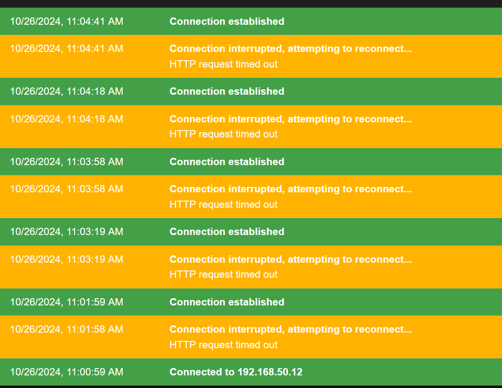
    I updated from 3.4.5 to 3.5.3 and instantly had HTTP dropouts every 20-40 sec.

    Running a 6XD on ethernet, so not used to having dropout issues.

    I downloaded the firmware from github and updated via the web interface, had issues, then downloaded the DuetWebControl-SD and also updated, still the same issues.

    Also cleared browser cache in desperation.
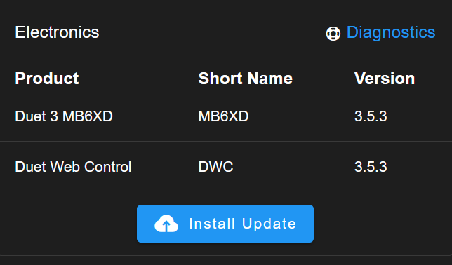
    shows as updated
    Screenshot 2024-10-26 112204.png

    Not sure what to do next.

    m122
    === Diagnostics ===
    RepRapFirmware for Duet 3 MB6XD version 3.5.3 (2024-09-18 11:27:56) running on Duet 3 MB6XD v1.0 (standalone mode)
    Board ID: 08DLM-956DA-M2NS4-6J1FD-3S06Q-9A26S
    Used output buffers: 1 of 40 (36 max)
    === RTOS ===
    Static ram: 153760
    Dynamic ram: 135120 of which 0 recycled
    Never used RAM 54256, free system stack 198 words
    Tasks: NETWORK(1,ready,35.0%,172) ETHERNET(5,nWait 7,0.2%,316) HEAT(3,nWait 6,0.0%,355) Move(4,nWait 6,0.0%,335) CanReceiv(6,nWait 1,0.0%,939) CanSender(5,nWait 7,0.0%,334) CanClock(7,delaying,0.0%,339) MAIN(1,running,64.5%,128) IDLE(0,ready,0.2%,29), total 100.0%
    Owned mutexes:
    === Platform ===
    Last reset 00:22:18 ago, cause: power up
    Last software reset at 2024-10-26 10:29, reason: User, Gcodes spinning, available RAM 57424, slot 2
    Software reset code 0x0003 HFSR 0x00000000 CFSR 0x00000000 ICSR 0x00400000 BFAR 0x00000000 SP 0x00000000 Task MAIN Freestk 0 n/a
    Error status: 0x00
    MCU temperature: min 25.0, current 32.8, max 33.4
    Supply voltage: min 24.0, current 24.1, max 24.2, under voltage events: 0, over voltage events: 0, power good: yes
    12V rail voltage: min 11.9, current 12.1, max 14.8, under voltage events: 0
    Heap OK, handles allocated/used 99/0, heap memory allocated/used/recyclable 2048/352/352, gc cycles 0
    Events: 4 queued, 4 completed
    Driver 0: ok
    Driver 1: ok
    Driver 2: ok
    Driver 3: ok
    Driver 4: ok
    Driver 5: ok
    Date/time: 2024-10-26 11:18:25
    Slowest loop: 850.08ms; fastest: 0.07ms
    === Storage ===
    Free file entries: 20
    SD card 0 detected, interface speed: 25.0MBytes/sec
    SD card longest read time 150.0ms, write time 136.4ms, max retries 0
    === Move ===
    DMs created 125, segments created 0, maxWait 0ms, bed compensation in use: none, height map offset 0.000, max steps late 0, min interval 0, bad calcs 0, ebfmin 0.00, ebfmax 0.00
    no step interrupt scheduled
    Moves shaped first try 0, on retry 0, too short 0, wrong shape 0, maybepossible 0
    === DDARing 0 ===
    Scheduled moves 0, completed 0, hiccups 0, stepErrors 0, LaErrors 0, Underruns [0, 0, 0], CDDA state -1
    === DDARing 1 ===
    Scheduled moves 0, completed 0, hiccups 0, stepErrors 0, LaErrors 0, Underruns [0, 0, 0], CDDA state -1
    === Heat ===
    Bed heaters -1 -1 -1 -1 -1 -1 -1 -1 -1 -1 -1 -1, chamber heaters -1 -1 -1 -1, ordering errs 0
    === GCodes ===
    Movement locks held by null, null
    HTTP is idle in state(s) 0
    Telnet is idle in state(s) 0
    File is idle in state(s) 0
    USB is idle in state(s) 0
    Aux is idle in state(s) 0
    Trigger is idle in state(s) 0
    Queue is idle in state(s) 0
    LCD is idle in state(s) 0
    SBC is idle in state(s) 0
    Daemon is idle in state(s) 0
    Aux2 is idle in state(s) 0
    Autopause is idle in state(s) 0
    File2 is idle in state(s) 0
    Queue2 is idle in state(s) 0
    Q0 segments left 0, axes/extruders owned 0x0000000
    Code queue 0 is empty
    Q1 segments left 0, axes/extruders owned 0x0000000
    Code queue 1 is empty
    === CAN ===
    Messages queued 6692, received 0, lost 0, errs 6318399, boc 0
    Longest wait 0ms for reply type 0, peak Tx sync delay 0, free buffers 50 (min 50), ts 6692/0/0
    Tx timeouts 0,0,6691,0,0,0 last cancelled message type 30 dest 127
    === Network ===
    Slowest loop: 137.33ms; fastest: 0.03ms
    Responder states: MQTT(0) HTTP(0) HTTP(0) HTTP(0) HTTP(0) HTTP(0) HTTP(0) FTP(0) Telnet(0) Telnet(0)
    HTTP sessions: 1 of 8
    = Ethernet =
    Interface state: active
    Error counts: 0 0 0 1 0 0
    Socket states: 5 2 2 2 2 0 0 0
    === Multicast handler ===
    Responder is inactive, messages received 0, responses 0
    

    Anyone having this issue? It is quite debilitating.

    Screenshot 2024-10-26 110510.png

    posted in Duet Web Control
    undefined
    SDJ
    26 Oct 2024, 10:24
  • RE: RapidChange Automatic Tool Changer on the Duet

    Oh I get it. This is screwing and unscrewing the collet nut. Crazy. I noticed you are using an air cooled spindle. I'm not sure I can run my spindle that slow without pissing off the VFD. It's a very short span of time I guess? I would have to lower my programmed limits to try this.

    "Tu fait quoi papa"

    "Un truc"

    Lol. Genial.

    posted in CNC
    undefined
    SDJ
    10 Apr 2024, 21:49
  • RE: RapidChange Automatic Tool Changer on the Duet

    Oooh this looks great. I would like to try this out on my next machine. Thanks for sharing.

    What are you using reverse for? I don't really see why you would require this for tool changes.

    posted in CNC
    undefined
    SDJ
    10 Apr 2024, 21:24
  • RE: Orca slicer and Duet

    I switched over to Orca Slicer when it looked like SuperSlicer had be abandoned after no updates since March. But I found a Sept post from the creator that says he is going to work on SS full time starting this month. I hope it's true.

    Screenshot 2023-11-19 175231.png

    From this post: https://github.com/supermerill/SuperSlicer/discussions/3902

    posted in General Discussion
    undefined
    SDJ
    19 Nov 2023, 18:58
  • RE: LJ12A3-4-Z/BX Proximity Sensor and 24V Relay with Optocoupler.

    Hello digital elf,

    In general it is best to used normally closed (NC) sensors. That way if there is an issue with the sensor the machine will refuse to home. I think the sensors you are using are normally open.

    Should still work fine, but I would suggest something like this: LJ12A3-4-Z/AX on this amazon page.

    Either way, the wiring should be nearly the same. Might have to switch the relay from high to low. Just test to see what works. Hold up something iron to the sensor and you should get the relay to switch on to off or opposite depending on how you wired it up.

    prox sensor setup Duet 2.jpg

    Hope that helps.

    posted in CNC
    undefined
    SDJ
    13 Aug 2023, 14:10
  • External Driver alarm wiring on 6XD

    Hello there,

    I have seen this question in the forums for other boards, but not the Duet 3 6xd with external drivers. This feels like one of those easy electronics questions that baffles people like me.

    I have a Duet 3 6XD (on 3.4.5) running closed loop drivers (Lichuan LCDA257S) which is similar to a CL57T from stepperonline which has ALM+ and ALM-. I am confused on how to wire this up to the duet.

    Duet 3 has a gnd pin and an Error pin (Dx_ERR) for each driver. The error pin meters 4.8v or so. I will check again tonight but I swear the pin is 4.8v regardless of the pull up/pull down selector.

    If it is grounded or goes to 5V, it triggers the driver error. Not sure why it is both. The error pin also has a physical selector for pull up/pull down on the board. I tried wiring up to ALM+ and ALM- in just about every configuration I could try and it would never trigger the error. Nothing worked. I tried 5V to ALM+ and ALM- to dx_ERR pin, dx_ERR to ALM+ and ALM- to gnd, etc. I thought this was a simple optocoupler that would close the contact. In normal state the ALM+ and ALM- reads 16 mOhms, in alarm state, this goes to 0. Why can't I trigger the error on the duet??

    Currently, my workaround is 24V to ALM+, ALM- to a separate 4 channel relay which closes a contact to ground out the dx_ERR pin. This works fine. I am ok with this workaround but it adds complexity.

    Am I missing a resistor somewhere to be able to hook straight up to the duet? Perhaps the separate channel relay is safer anyway by putting an optocoupler in the way.

    For clarity, this is the drive pins:
    Screenshot 2023-02-12 at 17.48.17.png

    The duet
    Screenshot 2023-02-12 at 15.00.56.png

    And the selector
    Screenshot 2023-02-12 at 16.07.45.png

    posted in General Discussion
    undefined
    SDJ
    14 Feb 2023, 11:08
  • RE: M569 config.g help for 6XD and external drivers

    @selva_tvi

    Hi selva, I'm working on this today. I just deleted another post trying to find out how to change the error pin pull up/down. Turns out there is a a spot to bridge it on the board itself. I will let you know how it goes. I am pretty close to finishing if this works.

    Screenshot 2023-02-12 at 16.07.45.png

    posted in CNC
    undefined
    SDJ
    12 Feb 2023, 16:09
  • Typo in 6XD wiring diagram

    There appears to be a typo in the Duet 3 6XD wiring diagram 1.0 and 0.1. Driver 2 should read D2 STEP-, D2 DIR-, D2 EN-, and D2_ERR not D4.

    Screenshot 2022-12-19 at 16.21.56.png

    posted in Documentation
    undefined
    SDJ
    19 Dec 2022, 16:38
  • RE: M569 config.g help for 6XD and external drivers

    @droftarts Hi Ian, thank you for the feedback. I think this makes sense to me now. It's closed loop between the motor and the external driver and it will attempt to return to the correct position but it is essentially open loop for the 6XD because the only info it has is whether or not the alarm function has gone off.

    I will try to figure out how the alarm works in testing. Or just throw up my hands and go EXP1HCL.

    @dc42 Thanks for the input. I will make those changes.

    posted in CNC
    undefined
    SDJ
    19 Dec 2022, 16:35
  • M569 config.g help for 6XD and external drivers

    I thought I'd give closed loop motors on the Duet 3 6XD a try. I just built the machine and have started working on the firmware though this flu might keep me from the workshop for now.

    I have installed Lichuan LC60H2102 Nema 24 1000ppr closed loop motors with LDCA257S drivers which appear to be a CL57T cloned clone. I can't seem to find a config.g file in the forums for the 6XD and external drivers as most of the configs out there are for expansion boards.

    I probably would have gone with 1XD expansion boards for these motors had I understood earlier that they could interface with common encoders. My loss.

    My problem: I am having a hard time understanding what needs to be declared in the config file for the external drivers. I started with my working 6HC config and changed the following:

    I commented out M906 for setting motor current as this is set by the ext. driver though the dictionary M906 states that all drives need this parameter. Not sure if it does.

    I upped the M350 microstepping from 16 to 32 as was suggested in the documentation to cover what the encoder could do. I doubled the steps per mm to 1280 from 640. I believe this is correct.

    For M569, I am not sure if I need the Taa:bb:cc:dd, Dnn, and Cnnn terms. Taa:bb:cc:dd seems needed because it controls the pulse widths for comms. Do I need to declare D4 for closed loop mode? Cnnn seem to be for specific chips. I don't know if I need these.

    And what about M569.1? Not sure if I need this. However, also my ext. driver has an alarm optorelay, so I've wired that to the DX_error pin of the Driver connections. If I don't need M569.1, How else would I control how many lost steps it takes for a warning or error? The ext. drive has its own Position error limit and alarm blinking LED, but I would rather have the duet handle those events so I can read the error messages. I guess i need to set the error limit higher on the ext drive so it doesn't trip first. Kinda lost here.

    Here is my config file so far.

    ; Drives
    M569 P0.0 S0 T5:5:5:5 D4                     ; physical drive 0 goes backwards - X axis with 5us timings between pulses
    M569 P0.1 S1 T5:5:5:5 D4                       ; physical drive 1 goes forwards - Y axis with 5us timings between pulses
    M569 P0.2 S0 T5:5:5:5 D4                       ; physical drive 2 goes backwards - Z axis with 5us timings between pulses
    M569 P0.3 S1 T5:5:5:5 D4                       ; physical drive 3 goes forwards - U axis with 5us timings between pulses
    M569.1 P0.0 T2 C5 E3:6                      ;configure X closed loop driver T2 is quadrature encoder type C is encoder pulses/rev E is warning:error full steps
    M569.1 P0.1 T2 C5 E3:6                      ;configure Y closed loop driver T2 is quadrature encoder type C is encoder pulses/rev E is warning:error full steps
    M569.1 P0.2 T2 C5 E3:6                      ;configure Z closed loop driver T2 is quadrature encoder type C is encoder pulses/rev E is warning:error full steps
    M569.1 P0.3 T2 C5 E3:6                      ;configure X closed loop driver T2 is quadrature encoder type C is encoder pulses/rev E is warning:error full steps
    
    M584 X0.0 Y0.1:0.3 Z0.2 U0.3 P3              ; set drive mapping - Y x:x sets Y and U together, P3 hides U axis
    M350 X32 Y32 Z32 U32 I0                      ; configure microstepping without interpolation
    ;M906 X3100 Y3100 Z3100 U3100 I40            ; set motor currents (mA) and motor idle factor in per cent
    
    ; Set axis dynamic parameters
    M92 X1280 Y1280 Z1280 U1280                 ; set steps per mm
    M566 X500 Y700 Z400 U700                    ; set maximum instantaneous speed changes (mm/min), 500 may be conservative
    M203 X2200 Y2500 Z2200 U2500                ; set maximum speeds (mm/min)
    M201 X50 Y50 Z50 U50                        ; set accelerations (mm/s^2)
    
    ; Set axis limits
    ;S0 set axis max and S1 set axis min
    M208 X0 Y0 Z-160 U0 S1			            ; set axis min
    M208 X571 Y700 Z0 U700 S0                   ; set axis max
    
    
    posted in CNC
    undefined
    SDJ
    19 Dec 2022, 01:07
  • RE: Fusion 360 CNC and laser post processors with tool workflow

    And here are the sys files.

    @sdj tpre2.g tpre1.g tpre0.g tpost0.g tfree1.g tfree0.g Probe.g config.g

    posted in CNC
    undefined
    SDJ
    2 Sept 2022, 16:44
  • RE: Fusion 360 CNC and laser post processors with tool workflow

    Here are the macros. Place them in a folder called mymacros

    @sdj Set Tool Height in g55.g Move To Probe Location in g55.g 04 - Set X Y Z Datum in g56 for laser.g 03 - Set X Y Datum In g55.g 02 - Set Probe to Waste Board Distance G55.g 01 - Set Probe Location.g

    posted in CNC
    undefined
    SDJ
    2 Sept 2022, 16:44
  • RE: Fusion 360 CNC and laser post processors with tool workflow

    Ok, here are the CNC and laser post processors. I have also included a sample output gcode from the CNC post processor. sample CNC PP gcode.gcode F360 Laser Duet PP.cps F360 Duet CNC PP.cps

    posted in CNC
    undefined
    SDJ
    2 Sept 2022, 16:42
  • Fusion 360 CNC and laser post processors with tool workflow

    Hello all,

    I thought I'd provide a workflow for those interested in using Fusion 360 for CNC and laser work. Hopefully it's useful.

    I'm running RRFW 3.3 on a Duet 3 running 32v for motors and 24v for most everything else. I'll cover how I build a tool library in Fusion 360 and call macros for a manual tool change between operations with a modified post processor for a pwm controlled spindle and a stationary z probe. I've also enabled arcs in this post processor.

    IMG_0681s.jpeg

    First setup your tool library in Fusion 360 including data on spindle speeds and feedrates.

    Screenshot 2022-09-02 at 16.12.56.png

    I reserve T1-T2 for defining tools such as spindles and laser engravers in my config files. Using T0 has caused me issues, so I avoid using that. Use T3 and above in Fusion 360 for defining bits. Note: a new tool will default to the lowest available number so make sure you add it to the bottom of the list. Save to the cloud tool library (preferences -> manufacture -> enable cloud libraries).

    In my config.g file, I have as many Tx as I have bits in my library.

    ; Tools
    ; No tool is selected at startup
    M453						                ; Set to CNC mode,
    M950 R0 C"out0+out6" Q300 L0:24000          ; Select Spindle On/Off,RPM & Direction (not selected).
    M563 P1 S"Laser"					; Create tool 1 Laser
    M563 P2 S"Spindle" R0				; Create tool 2 with Spindle
    
    ; Create enough tools to cover library of F360 CAM tools and link to R0
    M563 P3 S"T3" R0
    M563 P4 S"T4" R0	
    M563 P5 S"T5" R0	                        
    M563 P6 S"T6" R0	
    M563 P7 S"T7" R0	
    M563 P8 S"T8" R0	
    M563 P9 S"T9" R0	
    M563 P10 S"T10" R0		
    
    ; PWM Laser Enable 1# 2
    M950 P1 C"io4.out"                      ; Use C"" for output - Opt Lasers enable input #1
    M42 P1 S0				                    ; Ensure P1 is off - enable input #1		
    

    Your CAM will show the tool numbers:
    Screenshot 2022-09-02 at 16.22.02.png

    Upload the post processor I have provided. The post processor will call for a tool change if required. It does this by calling on macros I have also provided here. If you want to run a different macro, simply open up the post processor in Visual Studio Code and change the file path at LINE 573, save, and reupload to F360.

    Screenshot 2022-09-04 at 12.33.05.png

    For the macros, these were written mostly by @EducatingSavvas for his moot line of CNC machines. I'll provide a workflow here as well as I think it's helpful.

    Again, my machine has a fixed z probe button just off the work area. macros 01-04 are for initial setup of the machine. 02 and 04 need to be changed when resurfacing the waste board

    01 - Set Probe Location
    first sets the location of the probe and permanently stores this info

    02 - Set Probe to Waste Board Distance G55
    Then stores the difference between the probe and the waste board.

    03 - Set X Y Datum In g55
    This sets the location of my machine X0 Y0 work coordinates

    04 - Set X Y Z Datum in g56 for laser
    I have a laser attached next to the spindle (magnetically removable optlaser). I use this macro to set the offset in X, Y, and Z. U simply make a mark with my CNC vbit in g55 at X0 Y0 then jog the laser over to the same spot and then use this macro for setting laser X0 Y0 and Z0 in g56. This means that the spindle and the laser are perfectly aligned.

    These next macros are called in the gcode during a tool change:

    Move To Probe Location in g55
    moves the spindle to the Z probe

    Set Tool Height in g55
    adjusts new tool to wasteboard Z0

    That's all there is to it.

    In F360, select the bottom of the stock for your origin point and this will correspond to Z0, the top of your waste board.

    Screenshot 2022-09-02 at 16.42.26.png

    I have also include Tpre, Tpost, and probe files for good measure.

    I keep getting a parse error when trying to upload files. I will try to post the files in a second thread.

    posted in CNC
    undefined
    SDJ
    2 Sept 2022, 16:40
  • RE: Looking for help with CNC builds to help me start.

    @ecmaker

    You should check out the Moot One plans. I built one and it works great. There is info for different bed sizes and a bill of materials. The plates can cut for you, the rest you source. https://miscpro.com/product/moot_one-desktop-cnc-machine/

    posted in CNC
    undefined
    SDJ
    9 Oct 2021, 12:36
  • RE: Assigning multiple Pins for CNC M3 command use?

    @eddiechilli

    Hello, Savvas and I have similar setups. I have a different VFD, but maybe this will help. My VFD needs a 0-10V PWM signal for spindle speed and a 10V trigger to turn on FWD. I'm running my Duet 2 at 24V, so I need a voltage converter. I am using 2x of these:
    0-10v.jpg

    Which drops the voltage down to 10V and can translate a 0-24V PWM into a 0-10V PWM signal. They are wired to e0Heat and e1Heat with this config setup in RRF3.3 and use M3 for Spindle On and M5 for spindle off.

    ;Tools
    ; No tool is selected at startup
    M453						                ; Set to CNC mode,
    M950 R1 C"e1heat+e0heat" L0:24000 Q300		; Select Spindle On/Off,RPM & Direction (not selected).
    M563 P0 S"Laser"					        ; Create tool 0 Laser
    M563 P1 S"Spindle" R1				        ; Create tool 1 with Spindle
    

    In previous firmware versions, I used

    ;CNC
    M950 P0 C"e0heat" Q300			; Allocate GPOP Port 0 to Heater 0
    M453 C"e1heat" Q300 R24000 T1	; Set to CNC mode, using Tool 1, 24000 Max RPM
    

    Which meant assigning the FWD to e0heat by turning the spindle on with M42 P0 S1 and off with M42 P0 S0. e1heat would control the spindle speed.

    I have tried other voltage regulators that did not work. These work for sure. Also, make sure to switch them from 5V to 24V using the jumper. Hope that helps.

    posted in CNC
    undefined
    SDJ
    22 Sept 2021, 19:15
  • RE: RRF3.3 can't control spindle and call CAM tools

    In a different thread @dc42 wrote:
    @dc42 said in What firmware version are you using?:

    Does that mean if R in M950 and P in M563 are the same number during CNC mode, I would not need to write P# when using an M3 command?

    Yes.

    Should any spindle defining commands be in the tfree#.g tpre#.g and tpost#.g? That is to say I load the spindle separately from config.g file?

    There is no need to do that. In config.g, define all your spindles, then for each tool specify which spindle it uses in its M563 command.

    //

    Ok, I think I get it. To config.g I added

    M563 P3 R2 S"T3" R2	
    M563 P4 R2 S"T4" R2	
    M563 P5 R2 S"T5" R2	
    M563 P6 R2 S"T6" R2	
    

    To the config file. But this basically means I need to do this 20 times to cover all the different bits that I use.

    Also noticed that you don't require Pn during M3 commands with any tool assigned to the spindle. but the spindle tool itself requires Pn presumable because M563 can't assign the spindle to the spindle itself. Not sure if this is a bug or by design.

    posted in CNC
    undefined
    SDJ
    18 Sept 2021, 18:23
Unless otherwise noted, all forum content is licensed under CC-BY-SA