@droftarts "Fan MOSFET blown - using different pin on RRF2.x" could be good, or something like that, it's up to you, thanks!
Posts made by supermarioprof
-
RE: Blown fan MOSFET, using different pin on RRF2.xposted in Duet Hardware and wiring
-
RE: Blown fan MOSFET, using different pin on RRF2.xposted in Duet Hardware and wiring
@droftarts said in FAN mosfet probably blown:
Edit the first post, you can change the thread title there.
Ianimpossible, too late... 🥺
-
RE: Blown fan MOSFET, using different pin on RRF2.xposted in Duet Hardware and wiring
@droftarts sure I can use an external MOSFET or a Fotek SSR.
thank you very much, M106... A is exactly what I was looking for! -
RE: Blown fan MOSFET, using different pin on RRF2.xposted in Duet Hardware and wiring
@Phaedrux Summer laziness, now I need my 3d printer to be working reliably for a while. during Christmas holiday I will upgrade to RRF3
-
RE: Blown fan MOSFET, using different pin on RRF2.xposted in Duet Hardware and wiring
@droftarts Oh my god I totally missed that line in the guide!
so, if I correctly understood:say I wanna use pin 8 <--> HEATER3
this should be these gcodes:
M307 H3 A-1 C-1 D-1
M42 P3 I1 S240I can't try right now, my damaged Duet3D is still under repair, but I will try as soon as possible.
Last question:
I will need to change my gcodes and my slicer settings, will I?
because FAN0, FAN1 e FAN2 are connected to specific pins (20-22), but my new fan1 should be pin 8, so what?p.s.: I would like to change the thread title so that it will be more inherent with current content, but....is it possible? I can't find any button or settings
-
RE: Blown fan MOSFET, using different pin on RRF2.xposted in Duet Hardware and wiring
@droftarts thanks for your help!
I understand your code, the problem is I'm under RRF 2.05.
Yes I know I should upgrade, it will be the next step.But: what to do with pins, PWM and expansion port under RRF 2.x?
I know about M42 but, obviously, I get an error, likeM42 P3 I1 S240 --> Error: M42: Logical pin X is not available for writing
this sounds ok, since I didn't define that pin with M950 like you did,
but M950 is for RRF 3.x only.
Which command for RRF 2.x? -
RE: Blown fan MOSFET, using different pin on RRF2.xposted in Duet Hardware and wiring
@Phaedrux I'm gonna changing them, with the aid of a local laboratory.
Concerning expansion port, I know I can't use for a direct load,
so I should use a simple Fotek SSR.
But...which command and which pin?It should be M42, but I'm having difficulties in order to understand the online guide and docs, which pin is available of PWM and pin numbering,
so any help will be appreciated, at least an example (ok, I don't want to get out of contest, here we are for mosfets) -
Blown fan MOSFET, using different pin on RRF2.xposted in Duet Hardware and wiring
I'm subscribing to "Stupid Guys Blowing MOSFET on Duet - Club".
Modifying a delta 3D printer effector I probably shorted FAN1 and FAN0 on an old Duet 3D board v1.03, inverting polarity, so now this is what I'm facing:- FAN0 not working in any way
- FAN1 not working in any way
- FAN2 seems to work but it never stops
3D printer still works, I had to print some PLA and connected fans to "Always on" pins and it worked, but, ok, it is not a real solution.
I did some test, using Test Fan macro and a multimeter, shorting on endstop because I removed Duet board from 3D printer, and these are voltages I collected
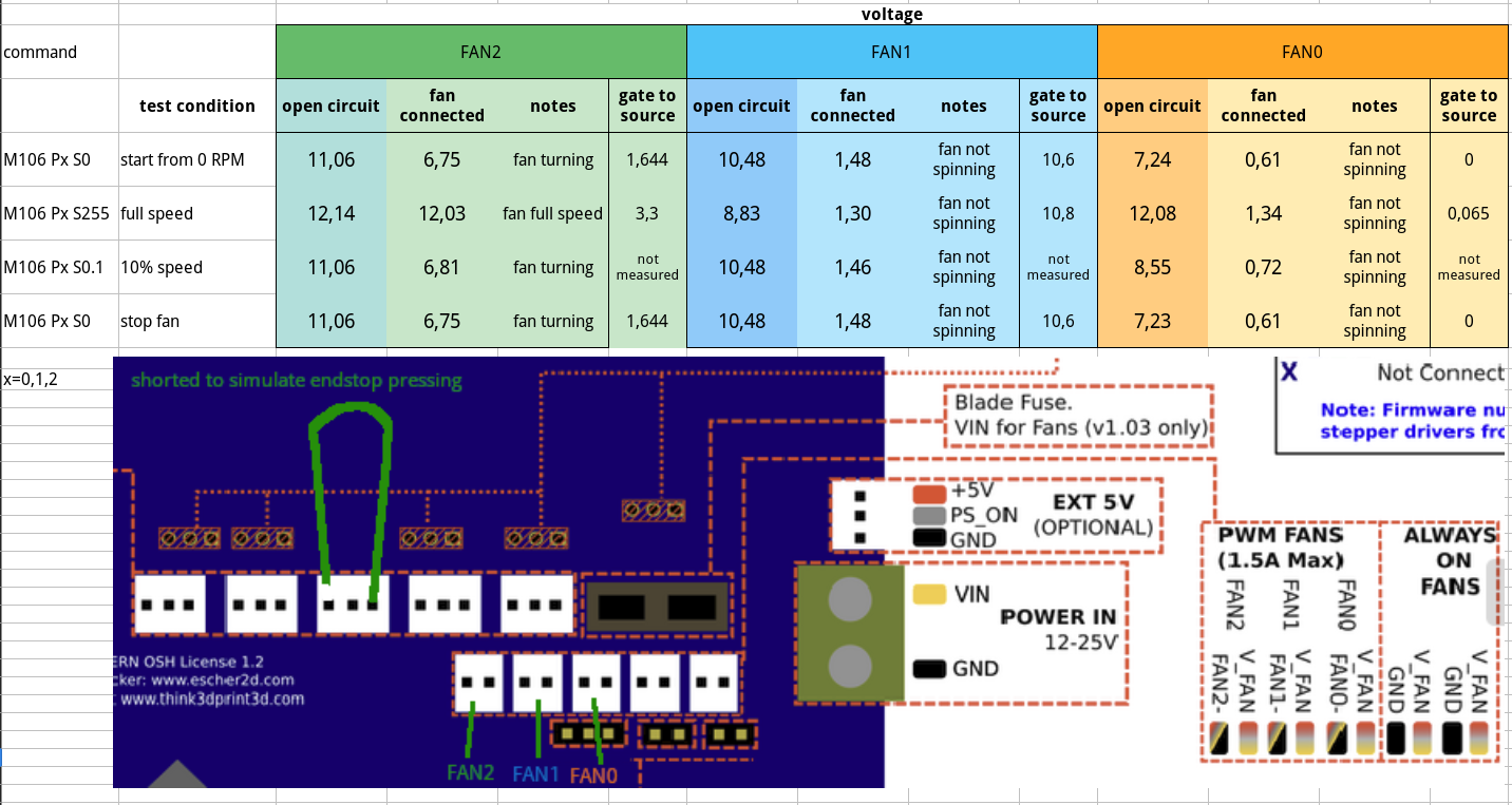
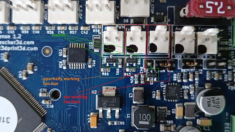
MOSFETs seem to be good at first sight (see photo)
I made also measures about gate to source on MOSFET, results on the first image.
My question: is this weird behaviour probably due to damaged MOSFETs?
since it is difficult to change them I would like to know more before starting desoldering,
Or could I use some PWM pin on expansion port? I had some readings but I didn't understand if this is possible -
RE: Last modified files as default viewposted in Duet Web Control
@chrishamm ok thanks! I will have a look for DWC 2 indeed!
-
RE: Last modified files as default viewposted in Duet Web Control
I'm on 1.22.6 because I prefer this version, is it possible to have " Last modified files" as default here too?
-
Last modified files as default viewposted in Duet Web Control
Is there any way to have "last modified" as default view in G-code files view?
Not the biggest problem in my life...
but it would be handy to have! -
Automatic shutdown without ATXposted in Duet Hardware and wiring
Hi! I'm looking for powering off my 3D printer and my Duet at the end of long prints and I'm facing some doubts.
I read about using ATX and PS_ON signal but in my 3D printer I use a simple PSU, so PS_ON is not available!
This is my current wiring:
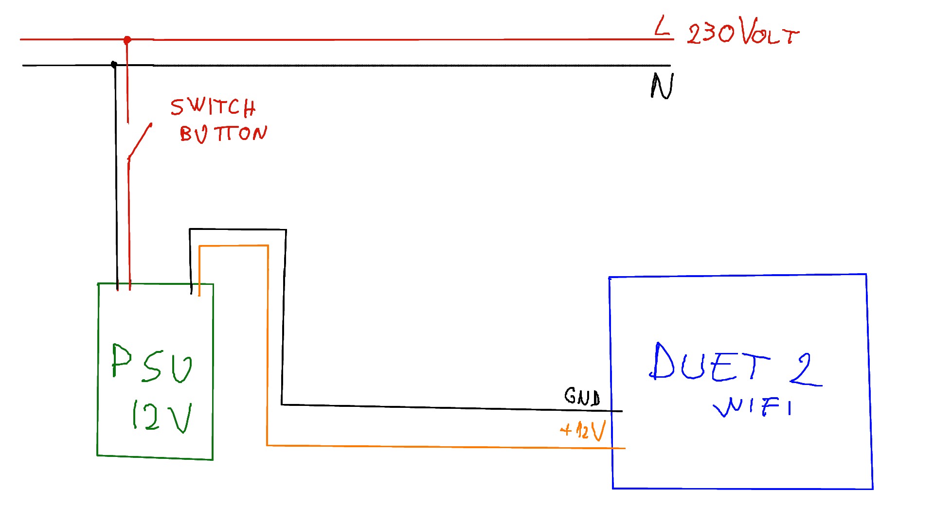
I would like my 3D printer to turn off automatically at the end of each print, in one of these cases, the first, the second or even together, this would be good but I can be satisfied with only one:
A. 3D print ended, hot-end temperature and bed temperature are under a defined trigger level
B. 3D print ended, defined time interval has passed, say 10 minutes
C. A OR B
D. A AND BThese are my work-in-progress schemes:
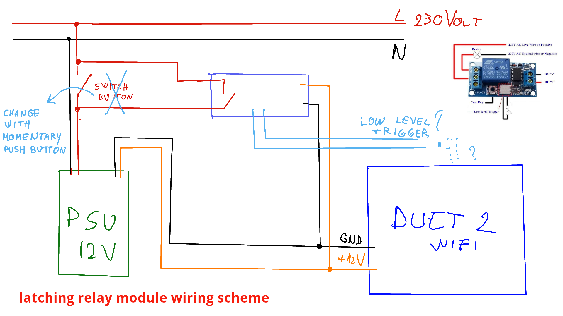
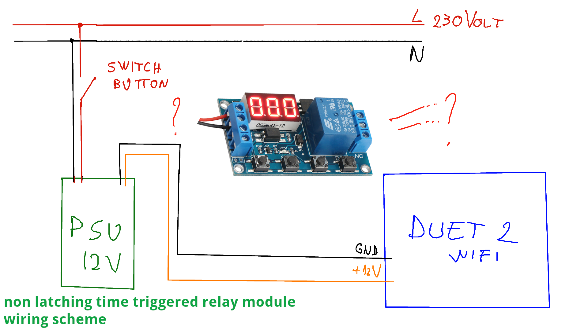
I've got a latching relay module (12V powered)
like this one
and a non latching time triggered relay module (6-30V powered)
like this one,
but I can buy others if needed.My questions:
- is the latching relay scheme correct? where should I connect low level trigger signal? to Duet GPIOs? and what g-code then, M42?
- how could I connect non latching time triggered relay module, which I could set to 10 minutes without using G4 g-code? is it possible to use in this wiring?
thanks in advance!
-
RE: Duet WiFi Access Point setup problemsposted in Firmware installation
@dc42 thanks!
I installed DuetWifiServer.bin AND Duet2CombinedFirmware.bin, 2.03beta1 (I installed before reading your answer!),
kept
M552 S0
G4 S5
M552 S2
and now access point mode works good! -
RE: Duet WiFi Access Point setup problemsposted in Firmware installation
@dc42 said in Duet WiFi Access Point setup problems:
Thanks for the feedback. I included this version of DuetWiFiServer with the RRF 2.03beta1 release. So anyone else having the same problem can pick it up from the 2.03beta1 release area.
I'm having similar problems with AP mode:
on every reboot
I need to open Pronterface,
force M552 S0,
force M552 S2 a few times (normally 3),
than AP mode goes on and everything works.I'm on latest stable, 2.02.
I also tried to add
M552 S0
G4 S5
M552 S2
in config.g, thinking it may be a question of time to wake up for AP mode. No joy.So:
-
should I update to 2.03beta1 or 2.03beta2?
-
should I update DuetWifiServer.bin only, or Duet2CombinedFirmware.bin too?
My config.g and SETNETWORK macro attached
thanks! -
-
RE: PNP inductive not properly workingposted in Duet Hardware and wiring
One more question: why does it work with lower resistor and not with higher ones? I would like to understand, anyone can share a simple scheme or drawing? I'm not so expert in electronics...
-
RE: PNP inductive not properly workingposted in Duet Hardware and wiring
You are right: lowering resistors to 10k and 34k (two 68k resistors in parallel) the inductive PNP NO sensor works as expected, digitally, setting M558 P5.
FYI: it worked in analog mode too, with previous resistors and setting M558 P1
-
RE: PNP inductive not properly workingposted in Duet Hardware and wiring
Sound strange, just verified: if I connect sensor to 12V external power supply I measure 0V when not triggered, 3.3V when triggered between signal (black wire) and GND (blue wire).
Will have a try on M558 P1
-
RE: PNP inductive not properly workingposted in Duet Hardware and wiring
One more thing:
measuring voltage between Black wire (sensor output) and GND
gives
1.32V when not triggered by metal, and led is off
3.27V when triggered by metal, and led is on -
PNP inductive not properly workingposted in Duet Hardware and wiring
Hi! I just connected a common LJ18A3-8-Z-BY PNP inductive sensor to my delta duetWifi 1.04 controlled: I added R1 and R2 resistors as explained in the guide, but I used 100K and 275K resistors since I haven't 10K and 30K now with me.
I plugged
blue --> Duet GND in Power In connector
black --> on Z_probe_IN, and R1 and R2 between
brown --> Vin 12V in Power In connectorWhen I turn on and pass some metal under sensor, onboard led turns on.
When I look at Setting --> Machine Properties: endstops triggers well by hand, from "no" to "yes", inductive sensor doesn't trigger even if onboard led turns on and stays "yes" all the time, so G30 doesn't work, obviously.What's wrong?
Too big resistors, so not enough current?
I upload my config.g in case it could help
0_1549107585880_config.g
I used
M558 P5 H4 F120 T3000 -
RE: 2nd thermistor and clogging alertposted in General Discussion
will have a look, thanks! On monday I should receive my new heatsink so I will make a hole in the currently mounted one, and share here results!