Duet3D Logo Duet3D
    • Tags
    • Documentation
    • Order
    • Register
    • Login
    1. Home
    2. tom_Nbg
    • Profile
    • Following 0
    • Followers 0
    • Topics 9
    • Posts 45
    • Best 1
    • Controversial 0
    • Groups 0

    tom_Nbg

    @tom_Nbg

    4
    Reputation
    3
    Profile views
    45
    Posts
    0
    Followers
    0
    Following
    Joined Last Online

    tom_Nbg Unfollow Follow

    Best posts made by tom_Nbg

    • Request for Mesh-Map / Bed-Level Corrections Features

      Hi,
      from the beginning with my DUET 2 wifi I had problems with the Mesh-Compensation. I'm not sure, if the problem comes from G32 and/or from sensitivity issues of my (original) BL-Touch (3.1).

      The Problem is, that there are regions (with higher deviations), where the compensation is too less. Here is a picture of the mesh-map and the resulting print. As you can see - where the bed is flat, the print is ok and there where are the "mountains" the compansations doesn't work reliable.
      mesh.jpg
      Datei_000 (5).jpeg

      This is repeatable - and I checked G32 and discussed this also in some other Forums.

      My thoughts: for any reason (maybe the magnets or magnet fields induced by the heat bed currents may have impacts on the BL-Touch measurements or sensitivity?

      Solution: & Request
      I remembered to a feature from the Prusa-Firmware called Bed-Level-Correction. There you can (virtually) raise or lower down some regions of the bed.

      I did this directly in the Meshmap as I changed the measured values on the left side of the bed (raised it up by +0.02 to +0.04). After this I made some finetunings on the rest regions. The result now is fine (see next picture) AND repeatable.
      Datei_000 (7).jpeg

      This way to "tweak" the meshmap is not very comfortable, so I would like to have this as feature in a future Firmware/DWC, where I can choose a pattern of the bed (3x3 or 4x4 or 5x5 ...) and can adjust corrections which should be done to the meshmap if they should be raised or lowered by a given level (here as a symbolic pictue as it could be look like). Actual I'm writing some Excel VBA-Macros for this job but it would be nice to have it directly in DWC.
      tweak.JPG

      I hope I could (with my poor english) figure out what I mean.
      Thank you!

      Tom

      PS: I was not sure where to post - maybe it should be placed in the DWC-Wishlist category? (@dc42 )

      posted in Firmware wishlist
      tom_Nbgundefined
      tom_Nbg

    Latest posts made by tom_Nbg

    • Request for Mesh-Map / Bed-Level Corrections Features

      Hi,
      from the beginning with my DUET 2 wifi I had problems with the Mesh-Compensation. I'm not sure, if the problem comes from G32 and/or from sensitivity issues of my (original) BL-Touch (3.1).

      The Problem is, that there are regions (with higher deviations), where the compensation is too less. Here is a picture of the mesh-map and the resulting print. As you can see - where the bed is flat, the print is ok and there where are the "mountains" the compansations doesn't work reliable.
      mesh.jpg
      Datei_000 (5).jpeg

      This is repeatable - and I checked G32 and discussed this also in some other Forums.

      My thoughts: for any reason (maybe the magnets or magnet fields induced by the heat bed currents may have impacts on the BL-Touch measurements or sensitivity?

      Solution: & Request
      I remembered to a feature from the Prusa-Firmware called Bed-Level-Correction. There you can (virtually) raise or lower down some regions of the bed.

      I did this directly in the Meshmap as I changed the measured values on the left side of the bed (raised it up by +0.02 to +0.04). After this I made some finetunings on the rest regions. The result now is fine (see next picture) AND repeatable.
      Datei_000 (7).jpeg

      This way to "tweak" the meshmap is not very comfortable, so I would like to have this as feature in a future Firmware/DWC, where I can choose a pattern of the bed (3x3 or 4x4 or 5x5 ...) and can adjust corrections which should be done to the meshmap if they should be raised or lowered by a given level (here as a symbolic pictue as it could be look like). Actual I'm writing some Excel VBA-Macros for this job but it would be nice to have it directly in DWC.
      tweak.JPG

      I hope I could (with my poor english) figure out what I mean.
      Thank you!

      Tom

      PS: I was not sure where to post - maybe it should be placed in the DWC-Wishlist category? (@dc42 )

      posted in Firmware wishlist
      tom_Nbgundefined
      tom_Nbg
    • RE: Mesh Compensation - big problems - something is wrong there

      Thank you for your reply and your thoughts
      I understand what you mean - and I never thought on this (allways my thought was, if there is a mechanical issue when moving BLTouch should detect it also... - but this enlighten me to this point).

      I'll have a look for and print another holder to mount the BLTouch on the right side - closer to the nozzle and with zero y-offset (there is a place at the BMG for the PINDA Probe) - so then the effect should get smaller or vanish.

      I'll report.
      Thank you again

      posted in General Discussion
      tom_Nbgundefined
      tom_Nbg
    • Mesh Compensation - big problems - something is wrong there

      Hi,
      I'm struggeling with my issue since weeks. I posted it here erlier, send my configs and till today nobody could found any reason for it.

      I entered a Facebook group (Duet3d Unofficial) and found out, that there are many more people with the same problem: mesh compensation didn't do it's job.

      After many discussions here and there I made some sequences to check if results are repeatable - and yes - it is. So my conclusion is, that there are somewhere deep in the RAM are old values stored which leads to wrong bed calculations.

      As I had independent z configured as first (with RRF2.0x) then went over to non-independent, went back to independent, go on to RRF3.0.xRCx. Having made a full earase and reinstalled the FW again - the issue is still there.

      So I asked again @dc42: do you have any idea, what could be the reason for, that the calculated bed didn't match manually measurements at all?

      I measured manually the same points which G29 did - and allways G29 delivers other results.

      The next: I power up, run
      M561
      G29 S2
      G32
      and got a correction of -0.065/0.059, then I run G32 again and got (as expected) -0.004/-0.002 (where it should be 0.0/0.0 - but errors in that range are ok).
      After this:
      G29
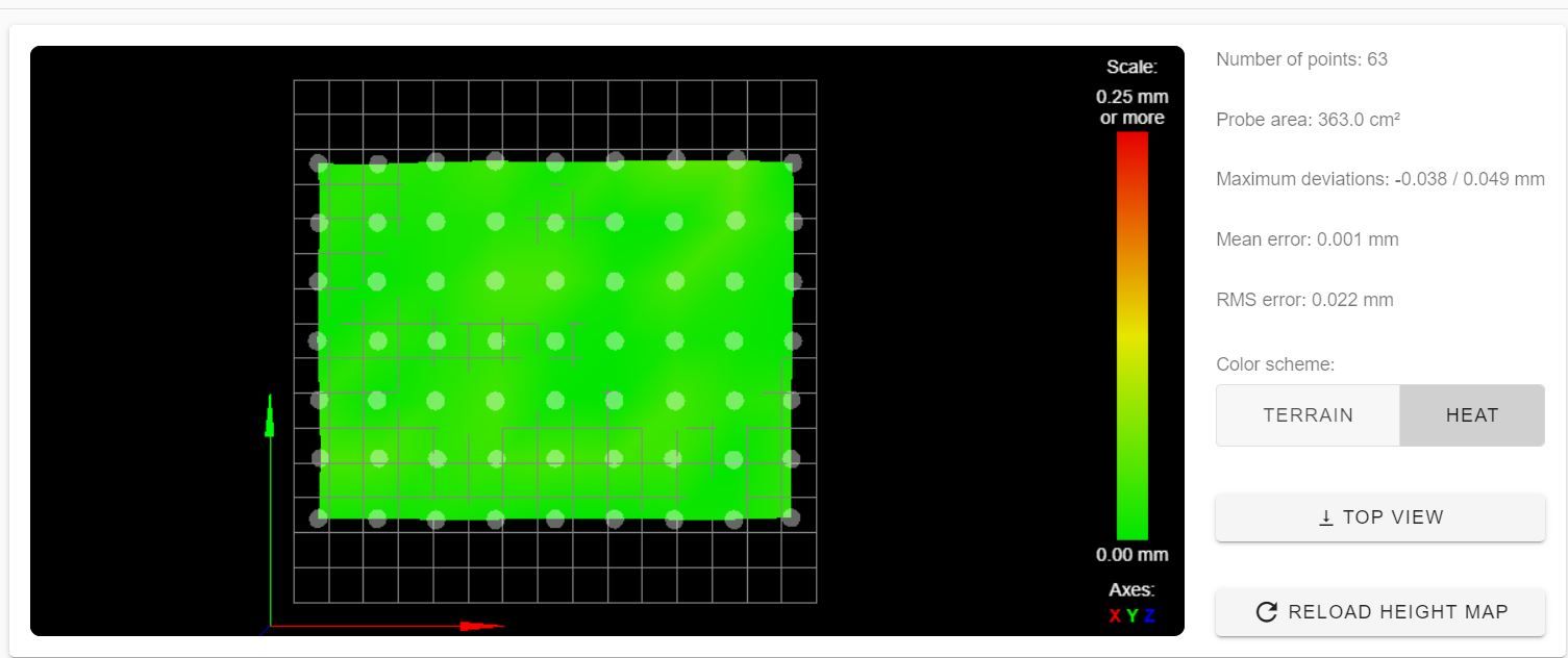
      49 points probed, min error -0.090, max error 0.046, mean -0.019, deviation 0.035
      which should be ok.
      Then after this I run G32 again (and it doesn't matter if I run again M561, G29 before ore not): -0.043/-0.026
      and this is repeatable as often as I like.
      When printing a test pattern allways on the left side the nozzle is to far from the bed, in the middle is ok and on the right side it is too close to the bed, and again - it does not depend from z-motor configuration if it is independent or not. Also I changed all steppers to exclude something here and the BLTouch. Only the Wifi-Board I didn't change till now.

      As readers shoudln't search for long, here are all machine details (but again - in the FB group are many user with different setups and the SAME problem!). I also add some pictures for the problems below.

      Printer is a Prusa-Like setup, Duet2 1.04 Wifi-Board, actual RRF3.01RC3
      x,y steppers: Nema17/48mm 1,8° / 200 steps / 2A,
      z-steppers Nema17 35mm 1,8° /200 steps / 1A with TR8x8 leadscrew
      Mosquito/BMG Hotend with stepper: 1.8°/200 steps / geared 1:3
      Magnetic MK52 Board@24 V, Meanwell 320W PSU, original BLTouch v3.1
      if I forgot details, please ask for.

      config.g

      G90                                                       ; send absolute coordinates...
      M83                                                       ; ...but relative extruder moves
      M550 P"Mjolnir"                                           ; set printer name
      
      ; Network
      M552 S1                                                   ; enable network
      M586 P0 S1                                                ; enable HTTP
      M586 P1 S1                                                ; enable FTP
      M586 P2 S0                                                ; disable Telnet
      
      ; Drives
      M569 P0 S0                                      		  ; physical drive 0 goes backwards - x-axis
      M569 P1 S0                                       		  ; physical drive 1 goes backwards - y-axis
      M569 P2 S0                                       		  ; physical drive 2 goes backwards - z - left
      M569 P3 S1                                       		  ; physical drive 3 goes forwards  - Extruder
      M569 P4 S0												  ; physical drive 4 goes backwards - r - right
      M584 X0 Y1 Z2:4 E3                                		  ; set drive mapping
      M671 X-36.5:293.5 Y0:0 S1.0 		   	   		 		  ; leadscrews at left (connected to Z) and right (connected to E1) of X axis
      M350 X16 Y16 E16 Z16 I1                                   ; configure microstepping with interpolation
      
      M92 X100.00 Y100.00 Z400.00 E415.00                       ; set steps per mm
      M566 X620.00 Y620.00 Z20.00 E300.00                       ; set maximum instantaneous speed changes (mm/min)
      M203 X12000.00 Y12000.00 Z360.00 E1800.00                 ; set maximum speeds (mm/min)
      M201 X1000.00 Y1000.00 Z200.00 E2000.00                   ; set accelerations (mm/s^2)
      M906 X1600 Y1600 Z850 E800 I30                              ; set motor currents (mA) and motor idle factor in per cent
      M84 S30                                                   ; Set idle timeout
      
      ; Axis Limits
      M208 X-1 Y-5 Z0 S1                                        ; set axis minima
      M208 X254 Y210 Z310 S0                                    ; set axis maxima
      
      ; Endstops
      M574 X1 S3                                                ; configure sensorless endstop for low end on X
      M574 Y2 S3                                                ; configure sensorless endstop for high end on Y
      M574 Z1 S2                                                ; configure Z-probe endstop for low end on Z
      M591 P2 C"e1_stop" S1									  ; configure extruder endtstop (filament sensor)
      
      ; Stallgaurd Sensitivy
      M915 X S2 F0 H200 R0		        	 				  ; Set X axis Sensitivity
      M915 Y S1 F0 H200 R0		          	 				  ; Set y axis Sensitivity
      
      ; Z-Probe
      M950 S3 C"exp.heater3"                                    ; create servo pin 0 for BLTouch
      M558 P9 C"^zprobe.in" H5 R0.25 S0.003 F120 T3000 A10 B1   ; set Z probe type to bltouch and the dive height + speeds
      G31 P125 X-22.6 Y-34.7 Z2.40                              ; set Z probe trigger value, offset and trigger height
      M557 X5:230 Y10:175 P7:7                                  ; define mesh grid
      
      ; Heaters
      M308 S0 P"bedtemp" Y"thermistor" T100000 B4138 A"Bed"     ; configure sensor 0 as thermistor on pin bedtemp
      M950 H0 C"bedheat" T0                                     ; create bed heater output on bedheat and map it to sensor 0
      M143 H0 S110                                              ; set temperature limit for heater 0 to 110C
      M307 H0 B0 S1.00                                          ; disable bang-bang mode for the bed heater and set PWM limit
      M140 H0                                                   ; map heated bed to heater 0
      M308 S1 P"e0temp" Y"thermistor" T500000 B4681 C1.143895e-7 A"Nozzle" ; configure sensor 1 as thermistor on pin e0temp
      M950 H1 C"e0heat" T1                                      ; create nozzle heater output on e0heat and map it to sensor 1
      M143 H1 S280                                              ; set temperature limit for heater 1 to 280C
      M307 H1 B0 S1.00                                          ; disable bang-bang mode for heater  and set PWM limit
      M308 S4 P"mcu-temp" Y"mcu-temp" A"MCU"					  ; set virtual heater for MCU
      M308 S5 P"drivers" Y"drivers" A"Driver"				      ; set virtual heater for stepper drivers
      
      ; Fans
      M950 F1 C"fan1" Q500                                      ; create fan 1 on pin fan0 and set its frequency
      M106 P1 S1 H1 T45                                         ; set fan 1 value. Thermostatic control is turned on
      M950 F0 C"fan0" Q500                                      ; create fan 0 on pin fan1 and set its frequency
      M106 P0 S0 H-1                                            ; set fan 0 value. Thermostatic control is turned off
      
      ; Tools
      M563 P0 D0 H1 F0                                          ; define tool 0
      G10 P0 X0 Y0 Z0                                           ; set tool 0 axis offsets
      G10 P0 R0 S0                                              ; set initial tool 0 active and standby temperatures to 0C
      M302 S190 R190
      
      ; Custom settings are not defined
      M501 													  ; use config-override (for Thermistor Parameters)
      

      homex.g

      G91                ; relative positioning
      G1 H1 Z5 F180
      G1 H1 X5 F1000     ; move slowly away 
      M913 X20           ; lower motor current to 20% for senserless homing
      G1 H1 X-260 F2000  ; move quickly to X axis endstop and stop there (first pass)
      G1 X10 F1000       ; go slowly back a few mm
      G1 H1 X-260 F2000  ; move to X axis endstop once more (second pass)
      M913 X100          ; Rise motor current to 100% again after sensorless homing
      G90                ; absolute positioning
      G1 X15 F1000	   ; go to X=15
      

      homey.g

      G91                ; relative positioning
      G1 H1 Y-5 F1000    ; move slowly away 
      M913 Y30           ; lower motor current to 30% for senserless homing
      G1 H1 Y230 F2000   ; move quickly to Y axis endstop and stop there (first pass)
      G1 Y-10 F1000      ; go back a few mm
      G1 H1 Y230 F2000   ; move slowly to Y axis endstop once more (second pass)
      M913 Y100          ; Rise motor current to 100% again after sensorless homing
      G1 Y-10 F1000      ; go back a few mm
      G90                ; absolute positioning
      

      homez.g

      G91                   ; relative positioning
      G90                   ; absolute positioning
      G1 X147.6 Y139.7 F3600    ; Move probe to middle of bed - first probing point, regarding Z-probe offsets
      G30                   ; home Z by probing the bed
      G91                   ; relative positioning
      G90                   ; absolute positioning
      

      homeall.g

      M98 P"homex.g"           ; Call "homex.g"
      M98 P"homey.g"           ; Call "homey.g"
      M98 P"homez.g"           ; Call "homez.g"
      

      bed.g

      M561 									; Clear any bed transform
      G29 S2									; Clear bed height map
      G30 P0 X10 Y105 Z-99999					; probe near left leadscrew, half way along Y axis
      G30 P1 X230 Y105 Z-99999 S2 			; probe near right leadscrew and calibrate 2 motors
      G90 									; Absolute Positioning
      G1 X125 Y105 Z25 F5000.0 		        ; go to the middle of the bed
      

      My normal start sequence:

      M561
      G29 S2
      G28
      G32
      G32 
      G29 (only at the moment - my aim is to get a reliable config, that I just to have load a mesh...)
      start print 
      

      As described here are the pictures:
      left
      IMG_1411.JPG

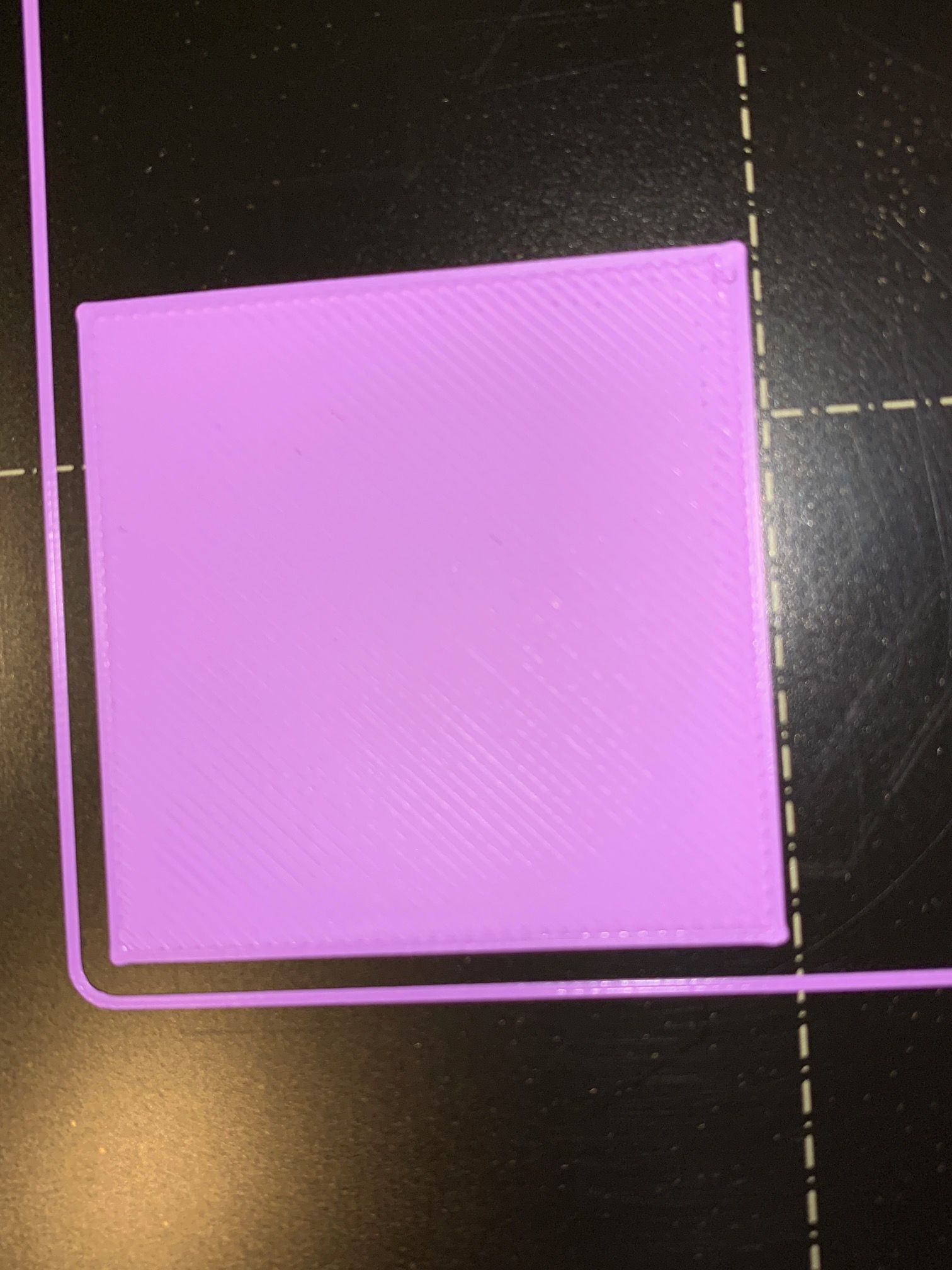
      right where you can clearly see, that the nozzle is way too deep:
      IMG_1406.JPG

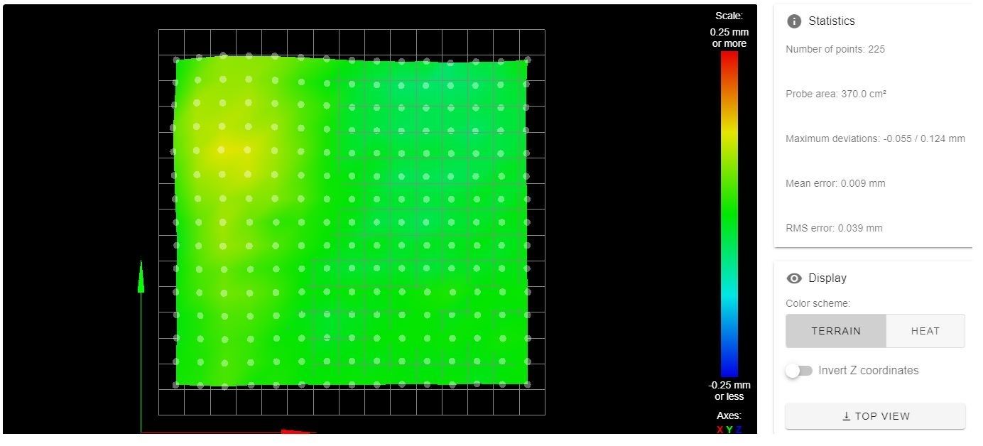
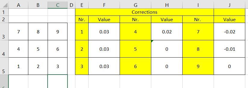
      mesh (which was measured for the prints in the pictures):
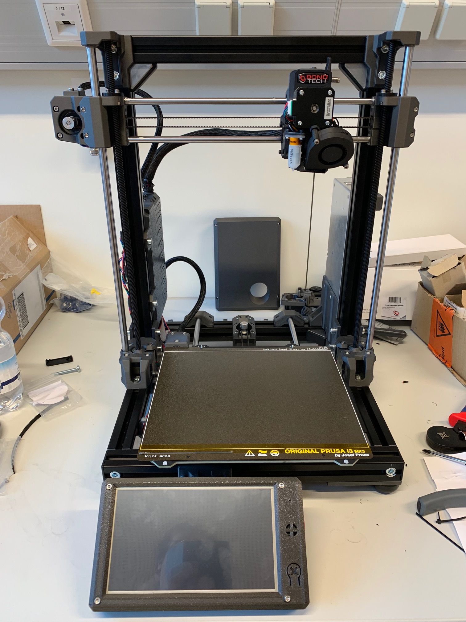
      Mesch_2.JPG

      printer:
      IMG_1213.jpg

      posted in General Discussion
      tom_Nbgundefined
      tom_Nbg
    • RE: Help: mesh compensation ist not correcting right

      @Phaedrux
      The problem is, that I need G32 because of the printers setup. When powering off or on the printer, the screws sometimes move a bit and so I have another tilt on the x-gantry...

      I'll try now to run my sequence without G29 and measure the 8 screw points manual with the macro above and put these values then into the heightmap. Then I'll look and maybe adjust the values comparing to print results and hope this will work for longer and only needs to adjust some baby steps....

      I had have a fully manually measured perfect mesh and the first layer was awsome - but after powering off and on the next day - and maybe I hit a bit the z-threads - it was totally horrible... because I hadn't had a G32 run...

      posted in General Discussion
      tom_Nbgundefined
      tom_Nbg
    • RE: Help: mesh compensation ist not correcting right

      @Phaedrux
      Hi re-checked all. I printed me some spacers of 8mm to check the bed level manual on each screw. It was fine. Then I'm gone through a sequence:

      • Power up
      • M561
      • G29 S2
      • G28
      • G32
        Then I checked again the Nozzle offset (screwed down the nozzle till it touches a piece of paper, rise it up for 5mm and run G30 S-1. I've done this for 3 times, mean 2.263, deviation 0.002 - so o.k.).
        Then I put in the new value to the G31 the config.g.
        After reboot:
      • M561
      • G29 S2
      • G28
      • G32
      • G29 (for a new meshmap with 7x7 grid)

      Then I looked to the map which just looked good for a test deviation mean 0.011, deviation 0.007
      After this I started a print and it was again the same suffering result... the left side is printed too high, the middle is ok and on the right side the nozzle is too close to - and it really looks as if where the left/right side mixed up (I checked this - it isn't so) - but I'm short befor to give up.

      This mesh compensation is a horror to get a good result over all. I've no clue if it an issue / interference problem between the BLTouch and the magnetic heatbed (but then why left/right - the magnets are placed symmetrically).

      I wonder also about this:
      After homing I go to the middle and checked the height (with a macro which measures 10 times) and I got -0.002 +/- 0.001. But the meshmap shows me at this point -0.019.
      Something is here very very wrong with G29.

      My very very last try will be to measure each point with my macro (see below) and I will recheck these measurements with the meshmap ones (I'll put in exactly the same positions from the meshmap) . If it is then still will not work, I'll make one last test with the Prusa-Pinda-Probe - and if it still will noch work - I'llsell the board...

      For more then 3 or 4 weeks now I don't can get a good first layer even a print. Also I recognized since the last update to RRF3.01RC3 that the board will loss every some minutes its network connection... I'm totally disappointed - I've expected more - and I'm sure, there are enough people out without problems like mine - but what is then their machine setup? If the baord is not suitable for my kind of printer - it should be mentioned somewhere...

      M401
      G30 P0 X10 Y175 Z-9999
      G30 P1 X10 Y175 Z-9999
      G30 P2 X10 Y175 Z-9999
      G30 P3 X10 Y175 Z-9999
      G30 P4 X10 Y175 Z-9999
      G30 P5 X10 Y175 Z-9999
      G30 P6 X10 Y175 Z-9999
      G30 P7 X10 Y175 Z-9999
      G30 P8 X10 Y175 Z-9999
      G30 P9 X10 Y175 Z-9999 S-1
      M402
      
      posted in General Discussion
      tom_Nbgundefined
      tom_Nbg
    • RE: Help: mesh compensation ist not correcting right

      I checked, if the correction is right and it is... I just put a 0.4mm spacer to the right side and the x-gantry was after G32 correct aligned to the bed... But my problem still exists... 😞 I've no further ideas anymore, what the problem could cause....

      posted in General Discussion
      tom_Nbgundefined
      tom_Nbg
    • RE: Help: mesh compensation ist not correcting right

      @Phaedrux
      no - it this was a copy/paste "rest" - and when I post it here I correct it to the inital state.
      y is on 1 (otherwise I think my z-axis would have crashed ;-). I swapped the z- and y-motor to to check if a driver has a problem. So my actual line is:

      M584 X0 Y1 Z2:4 E3    
      
      posted in General Discussion
      tom_Nbgundefined
      tom_Nbg
    • RE: Help: mesh compensation ist not correcting right

      @stewwy
      I run G32 before I start a print. So if the meassured distance on the right side is different to the left one - then the motors are getting corrected independent - and if then I have my case 1 or case 2 as drawn, the corrections are made are wrong. Example: the right side is too high, the right screw has to rise up but the fw "thinks" the bed has to lower down, then the gantry get lowered down and the effect is, that the nozzle is even closer than it should.... and this is it what I have.... So the measured values just need to be inverted or something like this...?

      posted in General Discussion
      tom_Nbgundefined
      tom_Nbg
    • RE: Help: mesh compensation ist not correcting right

      @stewwy
      Yes: the measured right side in the heightmap.csv is "deeper" then the left side, but I see, that it is higher - so the values are mixed up... How to tell the printer that?

      posted in General Discussion
      tom_Nbgundefined
      tom_Nbg
    • RE: Help: mesh compensation ist not correcting right

      @Phaedrux
      Hi,
      how do I configure or define what "bed type" I have? I mean:

      • if I have a "fixed x-gantry" and a "movable" bed (case 1) or
      • a "fixed bed" and a movable "x-gantry" (case 2). To illustrate see my both pictures below:

      The corrections to be made are allways in the opposite direction when running G32 if I have Case 1 or Case 2. And for mesh compensation the same. And it would explain, why on the right side, which is higher (the nozzle have to move up), it is getting close (because the correction is made in the opposite direction) and why it is on the left side in the opposite - and why the middle is mostly ok because it is more or less the pivot point?

      Could this be the problem or am I on a totally wrong way and didn't see anything else?

      IMG_1428.jpg
      IMG_1429.jpg
      IMG_1430.jpg

      posted in General Discussion
      tom_Nbgundefined
      tom_Nbg