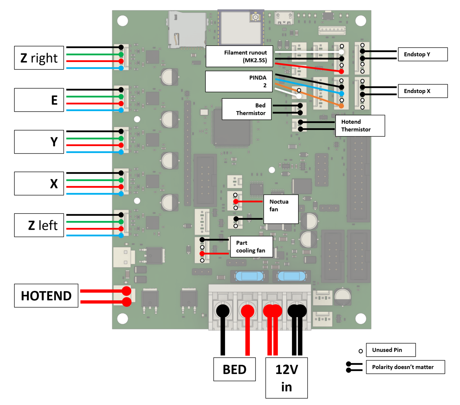
I am rebuilding a Prusa mk2.5s to use a duet 3 mini 5+. I am using a bulk of the code from CNCkitchen's guide but I changed some of the probe settings according to this forum.
This left me with this config file:
; Configuration file for Duet 3 Mini 5+ (firmware version 3)
; executed by the firmware on start-up
;
; generated by RepRapFirmware Configuration Tool v3.2.3 on Mon Mar 15 2021 19:09:36 GMT+0100 (Mitteleuropäische Normalzeit)

; ##### General preferences
M575 P1 S1 B57600                                                   ; enable support for PanelDue
G90                                          						; send absolute coordinates...
M83                                          						; ...but relative extruder moves
M550 P"Prusa MK2.5S DUET"                          					; set printer name

; ##### Network
M552 S1                                      						; enable network
M586 P0 S1                                   						; enable HTTP
M586 P1 S0                                  						; disable FTP
M586 P2 S0                                   						; disable Telnet

; ##### 12864 Menu
M918 P2 E-4

; ##### Drives
M569 P1 S0 D3 V10                                					; X drive @1
M569 P2 S0 D3 V10                                					; Y drive @2
M569 P0 S0 D3 V100                               					; Z left drive @0
M569 P4 S0 D3 V100                               					; Z right drive  @4
M569 P3 S1 D3 V0                                					    ; E drive @3 - inversed
M584 X1 Y2 Z0:4 E3                     								; set drive mapping
M671 X-37:287 Y0:0 S10                                     			; define dual driven z-axis

M350 X16 Y16 Z16 E16 I1                      						; configure microstepping with interpolation
M92 X100.00 Y100.00 Z400.00 E140.00             					; set steps per mm
M566 X600.00 Y600.00 Z48.00 E300.00        							; set maximum instantaneous speed changes (mm/min)
M203 X8000.00 Y8000.00 Z720.00 E7200.00      						; set maximum speeds (mm/min)
M201 X1250.00 Y1250.00 Z1250.00 E2000.00        					; set accelerations (mm/s^2)
M906 X750 Y750 Z600 E700 I30                						; set motor currents (mA) and motor idle factor in per cent
M84 S30                                      						; Set idle timeout

; ##### Axis Limits
M208 X0 Y-4 Z0 S1                             						; set axis minima
M208 X255 Y212.5 Z215 S0                       						; set axis maxima

; ##### Endstops
M574 X1 S1 P"io5.in"                        						; X endstop
M574 Y1 S1 P"io1.in"                        						; Y endstop

; ##### Filament Sensor
M591 D0 P2 C"io3.in" S1                                    			; Filament Runout Sensor

; ##### Z-Probe Settings for PINDA 2
M558 P8 C"io2.in" H1 F1000 T6000 A3              				; Prusa PindaV2 Endstop
M308 S2 P"temp2" A"Pinda V2" Y"thermistor" T100000 B3950      		; Prusa PindaV2 Thermistor
;G31 P500 X23 Y5 Z1.4 S21 H2 T0.02                         			; Nozzle offset - Powder Coated Sheet with temperature compensation (0.02mm/°C)
G31 P500 X23 Y5 Z1.1 S21 H2 T0.02                                    			; Nozzle offset - Smooth Sheet
M574 Z1 S2                                                 			; Set Z axis endstop, controlled by probe
M557 X24:228 Y6:210 P5                                    			; Define mesh grid for probing
M376 H5																; Fade height 5mm

; ##### Heaters
; Bed Heater
M308 S0 P"temp1" Y"thermistor" B4725 C7.060000e-8 					; configure sensor 0 as thermistor on pin temp1
M950 H0 C"out0" Q25 T0                           					; create bed heater output on out0 and map it to sensor 0, PWM frequency: 25Hz
M307 H0 R0.262 C338.0 D10.52 S1.00 V11.8 B0							; Bed tuning values, enable PID
M140 H0                                                    			; Bed uses Heater 0
M143 H0 S120                                               			; Set temperature limit for heater 0 to 120C Bed
; Hotend heater
M308 S1 P"temp0" Y"thermistor" B4725 C7.060000e-8 					; configure sensor 1 as thermistor on pin temp0
M950 H1 C"out1" T1                           						; create nozzle heater output on out1 and map it to sensor 1
M307 H1 B0 S1.00                             						; disable bang-bang mode for heater  and set PWM limit
M143 H1 S295                                 						; set temperature limit for heater 1 to 295C
M302 S170 R170                                         				; allow extrusion starting from 170°C and retractions already from 170°C

; ##### Fans
; Part cooling fan
M950 F0 C"out3" Q100                         						; create fan 0 on pin out3 and set its frequency
M106 P0 S0 H-1                               						; set fan 0 value. Thermostatic control is turned off
; Hotend cooling fan
M950 F1 C"out6" Q5000												; NOCTUA fan an pin out6 with 5000Hz PWM frequency
M106 P1 T55 S255 H1  												; Temperature control: turn fan on at 55°C

; ##### Tools
M563 P0 D0 H1 F0                             						; define tool 0
G10 P0 X0 Y0 Z0                              						; set tool 0 axis offsets
G10 P0 R0 S0                                 						; set initial tool 0 active and standby temperatures to 0C
M572 D0 S0.06								 						; Pressure Advance

; ##### Startup
M18 XYE0                                                				; release / unlock X, Y, and E axis
M501                                                   				; use config-override (for Thermistor Parameters and other settings)
G90                                                    				; send absolute coordinates...
M83                                                   				; ... but relative extruder moves
And this is how my bed.g file looks currently (theres a pretty good explenation as to why it is like this in this forum) :
; called to perform automatic bed compensation via G32
;
; generated by RepRapFirmware Configuration Tool v3.2.3 on Mon Mar 15 2021 19:09:36 GMT+0100 (Mitteleuropäische Normalzeit)
M561                                                       ; Clear any existing bed transform.
G28 ; home
G1 Z220 F10000
M558 F10000
G30

M558 F100 A5 S0.003
G30 P0 X25 Y105 Z-99999 ; probe near a leadscrew, half way along Y axis
G30 P1 X215 Y105 Z-99999 S2 ; probe near a leadscrew and calibrate 2 motors

M558 F200 A1

G1 X10 Y210 Z10 F10000
But, when I run bed.g, the printer says this error after going to the first probing point: "Error: Probe already triggered at start of probing move" and then, at the second probing point it has this error: "Error: Probe was not triggered during probing move". This also occurs when I try to run the mesh bed compensation via G29, the printer goes to the first probing point and then says Error: Probe already triggered at start of probing move, stopping there and doing nothing else. I have tried to fix this issue, but I can't find any solution or reason as to why it's doing what it's doing. So here I am now...
Side note: In CNCKitchen's original files, in the config.g file, on line 87, it said M18 XYE. But, whenever I tried to save the config, the board said this:
M98 P"config.g"
HTTP is enabled on port 80
FTP is disabled
TELNET is disabled
Error: in file macro line 87 column 8: M18: expected number after 'E'
So, I changed it to the current "M18 XYE0", which resulted in the board saying this instead:
M98 P"config.g"
HTTP is enabled on port 80
FTP is disabled
TELNET is disabled
Does this matter?
Thank you for your time and help