Probing Errors with Prusa mk2.5s and PINDA sensor
-
I am rebuilding a Prusa mk2.5s to use a duet 3 mini 5+. I am using a bulk of the code from CNCkitchen's guide but I changed some of the probe settings according to this forum.
This left me with this config file:; Configuration file for Duet 3 Mini 5+ (firmware version 3) ; executed by the firmware on start-up ; ; generated by RepRapFirmware Configuration Tool v3.2.3 on Mon Mar 15 2021 19:09:36 GMT+0100 (Mitteleuropäische Normalzeit) ; ##### General preferences M575 P1 S1 B57600 ; enable support for PanelDue G90 ; send absolute coordinates... M83 ; ...but relative extruder moves M550 P"Prusa MK2.5S DUET" ; set printer name ; ##### Network M552 S1 ; enable network M586 P0 S1 ; enable HTTP M586 P1 S0 ; disable FTP M586 P2 S0 ; disable Telnet ; ##### 12864 Menu M918 P2 E-4 ; ##### Drives M569 P1 S0 D3 V10 ; X drive @1 M569 P2 S0 D3 V10 ; Y drive @2 M569 P0 S0 D3 V100 ; Z left drive @0 M569 P4 S0 D3 V100 ; Z right drive @4 M569 P3 S1 D3 V0 ; E drive @3 - inversed M584 X1 Y2 Z0:4 E3 ; set drive mapping M671 X-37:287 Y0:0 S10 ; define dual driven z-axis M350 X16 Y16 Z16 E16 I1 ; configure microstepping with interpolation M92 X100.00 Y100.00 Z400.00 E140.00 ; set steps per mm M566 X600.00 Y600.00 Z48.00 E300.00 ; set maximum instantaneous speed changes (mm/min) M203 X8000.00 Y8000.00 Z720.00 E7200.00 ; set maximum speeds (mm/min) M201 X1250.00 Y1250.00 Z1250.00 E2000.00 ; set accelerations (mm/s^2) M906 X750 Y750 Z600 E700 I30 ; set motor currents (mA) and motor idle factor in per cent M84 S30 ; Set idle timeout ; ##### Axis Limits M208 X0 Y-4 Z0 S1 ; set axis minima M208 X255 Y212.5 Z215 S0 ; set axis maxima ; ##### Endstops M574 X1 S1 P"io5.in" ; X endstop M574 Y1 S1 P"io1.in" ; Y endstop ; ##### Filament Sensor M591 D0 P2 C"io3.in" S1 ; Filament Runout Sensor ; ##### Z-Probe Settings for PINDA 2 M558 P8 C"io2.in" H1 F1000 T6000 A3 ; Prusa PindaV2 Endstop M308 S2 P"temp2" A"Pinda V2" Y"thermistor" T100000 B3950 ; Prusa PindaV2 Thermistor ;G31 P500 X23 Y5 Z1.4 S21 H2 T0.02 ; Nozzle offset - Powder Coated Sheet with temperature compensation (0.02mm/°C) G31 P500 X23 Y5 Z1.1 S21 H2 T0.02 ; Nozzle offset - Smooth Sheet M574 Z1 S2 ; Set Z axis endstop, controlled by probe M557 X24:228 Y6:210 P5 ; Define mesh grid for probing M376 H5 ; Fade height 5mm ; ##### Heaters ; Bed Heater M308 S0 P"temp1" Y"thermistor" B4725 C7.060000e-8 ; configure sensor 0 as thermistor on pin temp1 M950 H0 C"out0" Q25 T0 ; create bed heater output on out0 and map it to sensor 0, PWM frequency: 25Hz M307 H0 R0.262 C338.0 D10.52 S1.00 V11.8 B0 ; Bed tuning values, enable PID M140 H0 ; Bed uses Heater 0 M143 H0 S120 ; Set temperature limit for heater 0 to 120C Bed ; Hotend heater M308 S1 P"temp0" Y"thermistor" B4725 C7.060000e-8 ; configure sensor 1 as thermistor on pin temp0 M950 H1 C"out1" T1 ; create nozzle heater output on out1 and map it to sensor 1 M307 H1 B0 S1.00 ; disable bang-bang mode for heater and set PWM limit M143 H1 S295 ; set temperature limit for heater 1 to 295C M302 S170 R170 ; allow extrusion starting from 170°C and retractions already from 170°C ; ##### Fans ; Part cooling fan M950 F0 C"out3" Q100 ; create fan 0 on pin out3 and set its frequency M106 P0 S0 H-1 ; set fan 0 value. Thermostatic control is turned off ; Hotend cooling fan M950 F1 C"out6" Q5000 ; NOCTUA fan an pin out6 with 5000Hz PWM frequency M106 P1 T55 S255 H1 ; Temperature control: turn fan on at 55°C ; ##### Tools M563 P0 D0 H1 F0 ; define tool 0 G10 P0 X0 Y0 Z0 ; set tool 0 axis offsets G10 P0 R0 S0 ; set initial tool 0 active and standby temperatures to 0C M572 D0 S0.06 ; Pressure Advance ; ##### Startup M18 XYE0 ; release / unlock X, Y, and E axis M501 ; use config-override (for Thermistor Parameters and other settings) G90 ; send absolute coordinates... M83 ; ... but relative extruder movesAnd this is how my bed.g file looks currently (theres a pretty good explenation as to why it is like this in this forum) :
; called to perform automatic bed compensation via G32
;
; generated by RepRapFirmware Configuration Tool v3.2.3 on Mon Mar 15 2021 19:09:36 GMT+0100 (Mitteleuropäische Normalzeit)
M561                                                       ; Clear any existing bed transform.
G28 ; home
G1 Z220 F10000
M558 F10000
G30

M558 F100 A5 S0.003
G30 P0 X25 Y105 Z-99999 ; probe near a leadscrew, half way along Y axis
G30 P1 X215 Y105 Z-99999 S2 ; probe near a leadscrew and calibrate 2 motors

M558 F200 A1

G1 X10 Y210 Z10 F10000
But, when I run bed.g, the printer says this error after going to the first probing point: "Error: Probe already triggered at start of probing move" and then, at the second probing point it has this error: "Error: Probe was not triggered during probing move". This also occurs when I try to run the mesh bed compensation via G29, the printer goes to the first probing point and then says Error: Probe already triggered at start of probing move, stopping there and doing nothing else. I have tried to fix this issue, but I can't find any solution or reason as to why it's doing what it's doing. So here I am now...
Side note: In CNCKitchen's original files, in the config.g file, on line 87, it said M18 XYE. But, whenever I tried to save the config, the board said this:
M98 P"config.g"
HTTP is enabled on port 80
FTP is disabled
TELNET is disabled
Error: in file macro line 87 column 8: M18: expected number after 'E'So, I changed it to the current "M18 XYE0", which resulted in the board saying this instead:
M98 P"config.g"
HTTP is enabled on port 80
FTP is disabled
TELNET is disabledDoes this matter?
Thank you for your time and help
-
@Trafim In DWC, what number does the Z-Probe report when the probe is far from the bed? If it is 1000, this means the firmware thinks the probe is already triggered. It should read 0. If you can put something under the probe, close to it, and then it reads 0, it means the probe has been wired 'inverted'. This would be a bit strange, as the signal should not need inverting. You can invert the pin logic in the M558 command by adding a
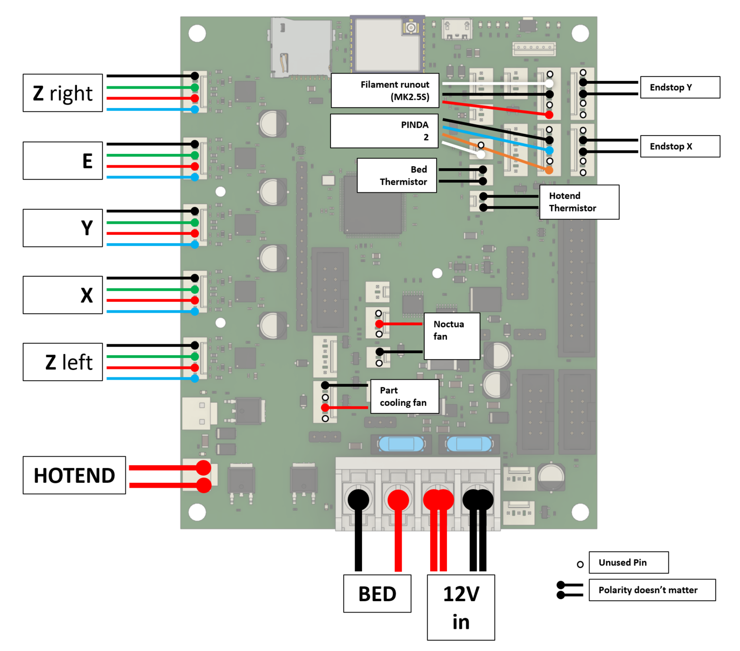
!at the beginning of the pin name, egM558 P8 C"!io2.in" H1 F1000 T6000 A3However, if the Z-Probe reading never changes, most likely there is a wiring error, and probably the signal wire is not making contact. Check all wiring connections; it may not be receiving power. Check it is plugged into the correct IO header. If the thermistor is reporting a sensible temperature, then at least the thermistor wire and GND are connected. If there is a light on the probe to show it is getting power (I can't remember if there is), and/or is triggered, this may help diagnose what the problem is. If you can post a picture of how it is wired, that may also help.
Regarding M18, as far as I'm aware, it has always needed an extruder drive number for E. See https://docs.duet3d.com/en/User_manual/Reference/Gcodes/M18
Ian
Bed-slinger - Mini5+ WiFi/1LC | RRP Fisher v1 - D2 WiFi | Polargraph - D2 WiFi | TronXY X5S - 6HC/Roto | CNC router - 6HC | Tractus3D T1250 - D2 Eth
-
@droftarts Yes, the probe does have a light on it, showing it is getting power, and it turns off when the probe is triggered. Everything is wired as such, and there is continuity in the wires:
When triggered the probe shows 1000, when not 0. I don't know where to look to find the thermistor readings of the Pinda sensor. Putting something metal under the sensor shoes it triggering correctly both on the sensor itself and in DWC. And after looking closely, it does seem that the probe is triggered before the probing move and the probe never triggers on the next probing move. But why? the bed nor X axis seem to be that badly out of alignment. After lowering it down to were the probe triggers, moving it to the other side does seems to stop it from triggering, but this issue seems to be very small. Isn't this compensation in place to fix just this?
With M18, its just a bit bizarre that that wasn't in the software from the RR config tool... / CNC Kitchen's tutorial. Would setting it to zero be the right thing to put there? What is an extruder drive number?
Sorry for the delay, Thank you!
-
@Trafim your dive height is set to 1mm (in the M558) in the config.g but your trigger height is more than that (1.1mm, in the G31). Since dive height is the height from which probing starts, I think it needs to be higher than trigger height. I'd try setting the H1 parameter in the M558 to be H3, then probably in due course refine it down to H1.5.
The rest of this is just my observations about a similarish configuration, not (I think) related to your problem.
I have a Pinda V2. Mine is a mini5+ and a toolboard, but apart from different pin names I think the config should be fairly similar.
My config.g (extract):
M308 S3 P"121.temp1" A"pinda" Y"thermistor" T100000 B3950 ; pinda thermistor
M558 P8 C"^121.io2.in" H2 A5 S0.005 F300:60 T6000  ; set Z probe type to unfiltered switch, dive height (2mm), max repetitions, tolerance, speeds
G31 P500 X23 Y5 Z0.87 T-0.000987:0.000245 S30 H3  ; set Z probe trigger value, offsets, trigger height and temperature compensation
M557 X25:240 Y6:204 P6:5                     ; define mesh grid
M376 H8                                      ; compensate first 8mm only
Compared to yours, I've specified up to 5 probes and much slower probe speeds (I use 300:60, you are using 1000 in the config.g but you drop it to 100 for some probes in bed.g. I found probing fast to be not nearly as accurate.
My G31 has very different temperature compensation. I use polynomial compensation, with a much lower coefficient. You can find a (long) discussion of that (with graphs) at https://forum.duet3d.com/post/309759
I have a different number of probe points x and y so each cell of the grid is closer to square.
In bed.g I have:
; bed.g
; called to perform automatic bed compensation via G32
;
M561                                    ; clear any bed transform

; probe across centreline of bed and level Z motors
G30 P0 X25 Y105 Z-99999
G30 P1 X240 Y105 Z-99999 S2
G4 P250                                 ; pause
G30 P0 X240 Y105 Z-99999                ; repreat process coming back again
G30 P1 X25 Y105 Z-99999 S2

G29                                     ; probe the bed and enable compensation

G1 Z5 F720
G1 X0 Y0 F6000
I'm not sure why you have other M558s in there rather than just setting a single config in confg.g (I want similar accuracy when setting the leadscrews as when doing mesh probing, so it's just a single set of speeds, tolerance etc.). I also don't bother homing again in this file.
I also do two passes, i.e. probe at left leadscrew the right leadscrew and compensate, then at right leadscrew and left left leadscrew again.
I don't know why you're using M18 at all - it lets the steppers float, but why? I don't use M18.
As to where to look to find the Pinda thermistor, you've defined it as being on pin 'temp2' and called it sensor 2 (S2 in the M308 line) and your wiring diagram looks compatible with that, so it should be showing in the DWC temperatures panel (under 'Extra'). You've named it 'Pinda V2'.
-
@achrn That seems to have fixed most of everything! I implemented what you told me and everything seems to be working, I just had to change the Z offset for my printer to get a good first layer. The extra M558s were part of the original tutorial, and I'm planning on phasing them out after reading up on them a little bit. Although, I do have another peculiar issue. The temperature readings for the PINDA V2 are negative... -26°C when turning on, and when printing they warmed up to around -17°C. Is this an incorrect config, or is the PINDA just done? The M18 was also part of the Firmware provided in the tutorial... I'll look into that as well.
Thank you for the info!
-
@Trafim your config looks OK to me (
M308 S2 P"temp2" A"Pinda V2" Y"thermistor" T100000 B3950) and matches what I have (M308 S3 P"121.temp1" A"pinda" Y"thermistor" T100000 B3950) but for the pin it's connected to and the number and name assigned. That's what I found online also (from a few sources, but I don't remember details). So I don't think it's a config issue.Temperature reading too low implies resistance is too high, so are the connections good? Is the cable good? What resistance do you measure across the pinda white and blue wires at the mini5 end? The thermistor ought to be reading 100k ohm at 25C, and a reading -26C suggests a resistance about 1.3M ohm. You could try connecting the pinda2 to temp1 (i.e. disconnect the bed thermistor) to see if that narrows down the problem (and indeed try connecting the bed thermistor to temp2 and see what that does).
Incidentally, with respect to the bed thermistor, my reading of the Prusa firmware source is that the bed thermistor is type 1 from 1_75mm_MK25S-RAMBo13a-E3Dv6full.h where #define TEMP_SENSOR_BED 1 and "1 is 100k thermistor - best choice for EPCOS 100k (4.7k pullup)". That thermistor is typically cited as B=4036, but back-calculation of the values in the source lookup table give best match if B=4078, I think.
However, the Prusa firmware seems to also add a 'fudge factor' or correction of 0 below 40C, 5C at 50C, 10C at 100C.
I trapped a couple of thermocouples under the magnetic plate and played around with B values until I got best correlation between what the bed was set to and what the thermocouples reported. That happened with a bed thermocouple B value of 4298. My bed thermistor is on temp0 so I have
M308 S0 P"temp0" A"bed" Y"thermistor" T100000 B4298for the bed thermistor. -
@Trafim I've had another thought - your reported temperatures are about what you'd get at normalish room temperatures if you'd configured it with
T10000instead ofT100000. Are you sure you have enough zeros? -
@Trafim Hello, I have uploaded all the files provided by CNCKitchen, I have them hosted on a Duet 3 prusa 2.5s they really do not work correctly, the z gives me error G28 from there I have not advanced since I lack a lot of knowledge and time since it is a hobby, would someone have the .G files, working on a prusa like the one I have? Thank you
-
@Trafim said in Probing Errors with Prusa mk2.5s and PINDA sensor:
Estoy reconstruyendo una Prusa mk2.5s para usar una duet 3 mini 5+. Estoy usando la mayor parte del código de la guía de CNCkitchen pero cambié algunas de las configuraciones de la sonda de acuerdo con este foro .
Esto me dejó con este archivo de configuración:It is possible that you upload your correct files so that I can use them, I had a problem with the CNCKitchen files, and I could not solve them, lack of knowledge I have a Prusa MK2.5s like you with a Duet 3 board. It is just a hobby Thank you
-
G28 Z Error: Homing file homez.g not found
-
@raftaman said in Probing Errors with Prusa mk2.5s and PINDA sensor:
G28 Z Error: Homing file homez.g not found
Do you have a homez.g file in your sys folder on the SD card?
-
@Phaedrux; 0:/sys/homez.g
; Home the Z axis;M98 P"current-sense-homing.g" ; Ensure the current and sensitivity is set for homing routines.
; !!! If using Pinda, comment-out the following two lines
;M280 P0 S160 ; BLTouch, alarm release.
;G4 P100 ; BLTouch, delay for the release command.G91 ; Set relative positioning.
G1 H0 Z3 F6000 ; Lift Z axis 3mm.
G90 ; Set absolute positioning.G1 X105 Y105 F6000 ; Go to the center of the bed for probe point.
M558 F1000 A1 ; Set probing speed to fast for the first pass.
G30 ; Perform Z probing.
G1 H0 Z5 F400 ; Lift Z axis to the 5mm position.M558 F50 A5 S-1 ; Set probing speed to slow for second pass, take 5 probes and yield the average.
G30 ; Perform Z probing.
G1 H0 Z5 F400 ; Lift Z axis to the 5mm position.M558 F200 A1 ; Set normal z-probe speed.
-
@raftaman said in Probing Errors with Prusa mk2.5s and PINDA sensor:
G28 Z Error: Homing file homez.g not found
When exactly are you getting that error?
-
@Phaedrux when I do a startup test on the Prusa mk2.5s
-
What is the startup test exactly?
-
@Phaedrux
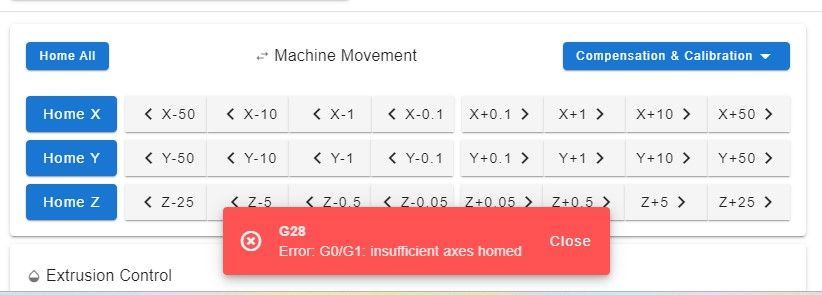 When I click on: Home All, I get that error. Home X, super, Home Y., Super, Home Z. Mistake
 -
@raftaman said in Probing Errors with Prusa mk2.5s and PINDA sensor:
G1 H0 Z3 F6000 ; Lift Z axis 3mm.
It's not saying homez.g not found, it's saying a move was attempted on an axis before it was homed. In your homez.g you have this G1 H0 move trying to lift the Z axis before it has been homed. This should be G1 H2 to allow the move to proceed even though it is not homed.
-
@PhaedruxWhat step should I take, what code should I include?
-
@Phaedrux said in Probing Errors with Prusa mk2.5s and PINDA sensor:
G1 H0 Z3 F6000 ; Lift Z axis 3mm.
@Phaedrux said in Probing Errors with Prusa mk2.5s and PINDA sensor:
This should be G1 H2 to allow the move to proceed even though it is not homed.
-
@PhaedruxI'M GOING TO TRY THIS WEEKEND WITH THE CODE YOU WRITE FOR ME. Thank