Duet3D Logo Duet3D
    • Tags
    • Documentation
    • Order
    • Register
    • Login
    1. Home
    2. vbuys
    3. Posts
    • Profile
    • Following 0
    • Followers 0
    • Topics 2
    • Posts 8
    • Best 0
    • Controversial 0
    • Groups 0

    Posts made by vbuys

    • RE: Dashboard Fan Object

      @deckingman @chrishamm Thanks for the replies! That clarifies things for me on how DWC operates. and it does make sense to keep it in light of @deckingman comments

      @deckingman said in Dashboard Fan Object:

      when you have selected P2 (both tools), the Tool Fan of DWC will control them both together, whereas selecting one of the other buttons will only control each fan individually.

      posted in Duet Web Control
      vbuysundefined
      vbuys
    • Dashboard Fan Object

      I'm trying to control two "fans" for use as part cooling on my 3HC expansion board using the "1.out3" and 1.out4" pins with 1 being the address of my board. I have the tools named "L Tool Air" and "R tool Air." It appears that in DWC, fan0 is automatically named "Tool Fan" under the dashboard "Fan Control" section. however, If I name F0 with C"L Tool Air" in setup, the Dashboard will list both Tool Fan and L Tool Air, with both controlling the same fan output. Is there a way to get rid of the automatic "Tool Fan" object in the dashboard so I only have my L Tool Air and Right Tool Air? I'm assuming the Hotend Fans don't show up, since they are thermostatically controlled?

      c0e6420a-eec6-4c19-9266-02158c2a4ab7-image.png

      ; General preferences
      G90                                                   ; send absolute coordinates...
      M83                                                   ; ...but relative extruder moves
      M550 P"Duet 3"                                        ; set printer name
      M150 X0												  ; set LED type to DotStar
      M150 R0 U0 B0 P0 S71								  ; clear all LEDs
      G4 S5												  ; allow time for 3HC to boot
      ; ***** Drives *****
      
      ; 6HC Main Board
      M569 P0.0 S0                                          ; physical drive 0.0 goes reverse 	- Right Y Axis
      M569 P0.1 S0                                          ; physical drive 0.1 goes reverse 	- X Axis Hotend
      M569 P0.2 S1                                          ; physical drive 0.2 goes forwards 	- Left Y Axis
      M569 P0.3 S1                                          ; physical drive 0.3 goes forwards 	- Left Extruder 
      M569 P0.4 S0                                          ; physical drive 0.4 goes reverse 	- U Axis Hotend
      M569 P0.5 S1                                          ; physical drive 0.5 goes forwards 	- Right Extruder
      M150 R255 U0 B0 P128 S5 F1							  ; set 5 LEDs to red
      
      ; 3HC Expansion Board
      M569 P1.0 S1                                          ; physical drive 1.0 goes forwards 	- Z Axis Front-Left
      M569 P1.1 S1                                          ; physical drive 1.1 goes forwards	- Z Axis Back-Center
      M569 P1.2 S1                                          ; physical drive 1.2 goes forwards	- Z Axis Front-Right
      M150 R255 U0 B0 P128 S5 F1							  ; set 5 LEDs to red
      
      ; set stepper parameters
      M584 X0.1 Y0.0:0.2 Z1.0:1.1:1.2 U0.4 E0.3:0.5         ; set drive mapping
      M350 X16 Y16 Z16 U16 E16:16 I1              		  ; configure microstepping with interpolation
      M92 X40.00 Y80.00 Z1600.00 U40.00 E400.00			  ; set steps per mm
      M566 X900.00 Y900.00 Z60.00 U900.00 E120.00           ; set maximum instantaneous speed changes (mm/min)
      M203 X12000.00 Y12000.00 Z1000.00 U12000.00 E1800.00  ; set maximum speeds (mm/min)
      M201 X500.00 Y500.00 Z20.00 U500.00 E250.00           ; set accelerations (mm/s^2)
      M906 X1500 Y1500 Z1500 U1500 E300 I30                 ; set motor currents (mA) and motor idle factor in per cent
      M84 S30                                               ; Set idle timeout
      M150 R255 U0 B0 P128 S5 F1							  ; set 5 LEDs to red
      
      ; Axis Limits
      M208 X0 Y0 Z0 U45 S1                                  ; set axis minima
      M208 X370 Y400 Z380 U411 S0                           ; set axis maxima
      M150 R255 U0 B0 P128 S2 F1							  ; set 2 LEDs to red
      
      ; Z leadscrew locations
      M671 X-54:206:466 Y-39.5:428:-39.5 S10	              ; three leadscrews at Front-Left, Back-Center, and Front-Right
      M150 R255 U0 B0 P128 S2 F1							  ; set 2 LEDs to red
      
      ; Endstops
      M574 X1 S1 P"io0.in"                                  ; configure active-high endstop for low end on X via pin io0.in
      M574 Y2 S1 P"io2.in+io1.in"                           ; configure active-high endstop for high end on Y via pin io1.in
      M574 U2 S1 P"io3.in"                                  ; configure active-high endstop for high end on U via pin io1.in
      M150 R255 U0 B0 P128 S5 F1							  ; set 5 LEDs to red
      
      ; Z-Probe
      M950 S0 C"1.io1.out"
      M558 P9 C"1.io1.in" F200 H5 R0 T6000 A S0.03 B1       ; set Z probe type to switch and the dive height + speed
      G31  X-5 Y21.75 Z3.8  	                          	  ; set Z probe offset and trigger height
      M557 X0:350 Y22:400 S50                               ; define mesh grid
      M150 R255 U0 B0 P128 S5 F1							  ; set 5 LEDs to red
      
      ; ***** Heaters *****
      
      ; Bed
      M308 S0 P"temp0" Y"thermistor" A"Bed Temp" T100000 B3950 		  ; configure sensor 0 as thermistor on pin temp0
      M950 H0 C"out0" T0                                    ; create bed heater output on out0 and map it to sensor 0
      M307 H0 R0.601 C403.2 D5.29 S1.00                     ; disable bang-bang mode for the bed heater and set PWM limit
      M140 H0                                               ; map heated bed to heater 0
      M143 H0 S120   										  ; set temperature limit for heater 0 to 120C
      M150 R255 U0 B0 P128 S5 F1							  ; set 5 LEDs to red
      
      ; Left Hotend (X)
      M308 S1 P"temp1" Y"thermistor" A"Left Temp" T100000 B4725 C7.06e-8 ; configure sensor 1 as thermistor on pin temp1
      M950 H1 C"out1" T1                                    ; create nozzle heater output on out1 and map it to sensor 1
      M307 H1 R2.392 C206.4 D5.67 S1.00 V24.0				  ; disable bang-bang mode for heater  and set PWM limit
      M143 H1 S280                                          ; set temperature limit for heater 1 to 280C
      M150 R255 U0 B0 P128 S5 F1							  ; set 5 LEDs to red
      
      ; Right Hotend (U)
      M308 S2 P"temp2" Y"thermistor" A"Right Temp" T100000 B4725 C7.06e-8 ; configure sensor 2 as thermistor on pin temp2
      M950 H2 C"out2" T2                                    ; create nozzle heater output on out2 and map it to sensor 2
      M307 H2 R2.132 C230.6 D5.30 S1.00 V24.0               ; disable bang-bang mode for heater  and set PWM limit
      M143 H2 S280                                          ; set temperature limit for heater 2 to 280C
      M150 R255 U0 B0 P128 S5 F1							  ; set 5 LEDs to red
      
      ; ***** Fans *****
      
      ; Left Tool Air (X)
      M950 F0 C"1.out3" Q50							      ; create fan 0 on pin 1.out3 and set its frequency
      M106 P0 C"L Tool Air"								  ; 
      
      ; Left Heater Fan (X)
      M950 F1 C"out7" Q250                                  ; create fan 1 on pin out7 and set its frequency
      M106 P1 S1 H1 T45 C"L Hotend Fan"                     ; set fan 1 value. Thermostatic control is turned on
      M150 R255 U0 B0 P128 S5 F1							  ; set 5 LEDs to red
      
      ; Right Tool Air (U)
      M950 F2 C"1.out4" Q50								  ; create fan 2 on pin 1.out4 and set its frequency
      M106 P2 C"R Tool Air"
      
      ; Right Heater Fan (U)
      M950 F3 C"out8" Q250                                  ; create fan 3 on pin out8 and set its frequency
      M106 P3 S1 H2 T45 C"R Hotend Fan"                     ; set fan 3 value. Thermostatic control is turned on
      M150 R255 U0 B0 P128 S5 F1							  ; set 5 LEDs to red
      
      ; ***** Tools *****
      
      ; Left Tool (X)
      M563 P0 S"Left" D0 H1 F0                              ; define tool 0
      G10 P0 X0 Y0 Z0                                       ; set tool 0 axis offsets
      G10 P0 R0 S0                                          ; set initial tool 0 active and standby temperatures to 0C
      M150 R255 U0 B0 P128 S5 F1							  ; set 5 LEDs to red
      
      ; Right Tool (U)
      M563 P1 S"Right" D1 H2 X3 F1                          ; define tool 1
      G10 P1 X45 Y0 Z0                                      ; set tool 1 axis offsets
      G10 P1 R0 S0                                          ; set initial tool 1 active and standby temperatures to 0C
      M150 R255 U0 B0 P128 S5 F1							  ; set 5 LEDs to red
      
      ; Dual Tools
      M563 P2 S"Dual" D0:1 H1:2 X0:3 F0:1
      G10 P2 X100 Y0 U-100 S0 R0
      M567 P2 E1:1
      M150 R255 U0 B0 P128 S5 							  ; set 5 LEDs to red
      
      ; Miscellaneous
      T0                                                    ; select first tool
      M150 R128 U36 B0 P128 S71						      ; set all LEDs to amber
      
      posted in Duet Web Control
      vbuysundefined
      vbuys
    • RE: 3HC CAN stopped connecting

      @phaedrux @dc42 Thank you both for your quick replies and all your help!

      posted in Duet Hardware and wiring
      vbuysundefined
      vbuys
    • RE: 3HC CAN stopped connecting

      @dc42 I tried with the BLTouch disconnected, as well as with the BLTouch and all steppers disconnected, but neither scenario made any difference and the 3.3v LED remains off.

      posted in Duet Hardware and wiring
      vbuysundefined
      vbuys
    • RE: 3HC CAN stopped connecting

      @phaedrux thanks for the suggestion. I added the G4 S5, but no change.

      M122 B1 reports :

      Error: M122: Response timeout: CAN addr 1, req type 6024, RID=9

      posted in Duet Hardware and wiring
      vbuysundefined
      vbuys
    • RE: 3HC CAN stopped connecting

      @dc42 only my 3 Z steppers and a BLTouch on IO_1.

      back electronics.jpg 3HC.jpg 3HC - close up.jpg

      posted in Duet Hardware and wiring
      vbuysundefined
      vbuys
    • RE: 3HC CAN stopped connecting

      Edit:
      After more digging into the issue, it appears not ALL power LEDs are lit. The Green 3.3V LED is not on. When I check the 3.3V probe point with a multimeter, I'm only getting .022v... What would cause the 3.3v to crap out like that? Would that impact the CAN bus? I'm assuming the Atmel microprocessor runs off the 3.3v supply. Is there a way to fix that other than scrapping the board?

      posted in Duet Hardware and wiring
      vbuysundefined
      vbuys
    • 3HC CAN stopped connecting

      Everything was working well, until it wasn't...

      I built a 3D printer using the 6HC and 3HC and was in the process of working through getting it dialed in. After an unsuccessful test, I went to level the bed again and the Z axis did not respond and threw numerous CAN bus errors. Now when I look at the 3HC, the DIAG LED is not longer flashing at all. It doesn't seem to even see the board any more. They were both running 3.2.2. When I restart the 6HC I get the following errors

      1e06ad4d-4d0f-4f9c-809a-2f9a62c36b14-image.png

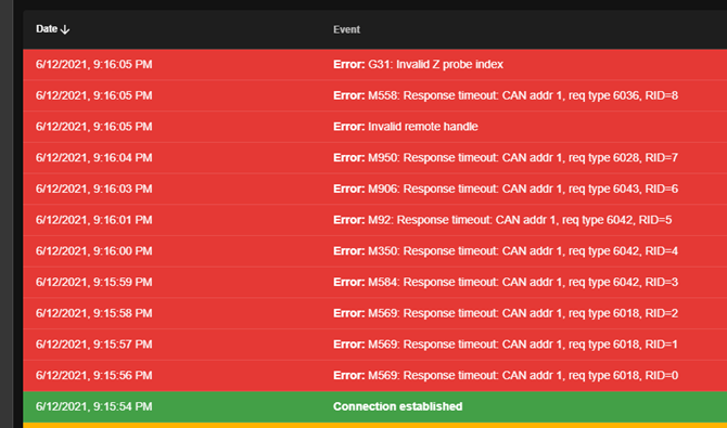
      All of the power LEDs on the 3HC are lighting, as usual, just no sync with the 6HC. When I run the Diagnostics, under the System > Machine-Specific tab, I get the following:

         M122
      === Diagnostics ===
      RepRapFirmware for Duet 3 MB6HC version 3.2.2 running on Duet 3 MB6HC v1.01 or later (SBC mode)
      Board ID: 08DJM-956L2-G43S8-6J1DG-3S46M-KV2YD
      Used output buffers: 1 of 40 (12 max)
      === RTOS ===
      Static ram: 149788
      Dynamic ram: 63500 of which 48 recycled
      Never used RAM 145496, free system stack 200 words
      Tasks: Linux(ready,101) HEAT(blocked,297) CanReceiv(blocked,927) CanSender(blocked,371) CanClock(blocked,352) TMC(blocked,53) MAIN(running,1149) IDLE(ready,19)
      Owned mutexes: HTTP(MAIN)
      === Platform ===
      Last reset 00:09:05 ago, cause: power up
      Last software reset details not available
      Error status: 0x00
      Aux0 errors 0,0,0
      Aux1 errors 0,0,0
      MCU temperature: min 39.7, current 42.4, max 42.6
      Supply voltage: min 24.1, current 24.1, max 24.1, under voltage events: 0, over voltage events: 0, power good: yes
      12V rail voltage: min 12.2, current 12.2, max 12.2, under voltage events: 0
      Driver 0: position 0, standstill, reads 34238, writes 0 timeouts 0, SG min/max not available
      Driver 1: position 0, standstill, reads 34239, writes 0 timeouts 0, SG min/max not available
      Driver 2: position 0, standstill, reads 34239, writes 0 timeouts 0, SG min/max not available
      Driver 3: position 0, standstill, reads 34239, writes 0 timeouts 0, SG min/max not available
      Driver 4: position 0, standstill, reads 34238, writes 0 timeouts 0, SG min/max not available
      Driver 5: position 0, standstill, reads 34238, writes 0 timeouts 0, SG min/max not available
      Date/time: 2021-06-12 22:08:49
      Slowest loop: 0.45ms; fastest: 0.04ms
      === Storage ===
      Free file entries: 10
      SD card 0 not detected, interface speed: 37.5MBytes/sec
      SD card longest read time 0.0ms, write time 0.0ms, max retries 0
      === Move ===
      DMs created 125, maxWait 0ms, bed compensation in use: none, comp offset 0.000
      === MainDDARing ===
      Scheduled moves 0, completed moves 0, hiccups 0, stepErrors 0, LaErrors 0, Underruns [0, 0, 0], CDDA state -1
      === AuxDDARing ===
      Scheduled moves 0, completed moves 0, hiccups 0, stepErrors 0, LaErrors 0, Underruns [0, 0, 0], CDDA state -1
      === Heat ===
      Bed heaters = 0 -1 -1 -1 -1 -1 -1 -1 -1 -1 -1 -1, chamberHeaters = -1 -1 -1 -1
      Heater 1 is on, I-accum = 0.0
      === GCodes ===
      Segments left: 0
      Movement lock held by null
      HTTP* is doing "M122" in state(s) 0
      Telnet is idle in state(s) 0
      File is idle in state(s) 0
      USB is idle in state(s) 0
      Aux is idle in state(s) 0
      Trigger* is idle in state(s) 0
      Queue is idle in state(s) 0
      LCD is idle in state(s) 0
      SBC is idle in state(s) 0
      Daemon is idle in state(s) 0
      Aux2 is idle in state(s) 0
      Autopause is idle in state(s) 0
      Code queue is empty.
      === CAN ===
      Messages queued 1833, send timeouts 4124, received 0, lost 0, longest wait 0ms for reply type 0, free buffers 48
      === SBC interface ===
      State: 4, failed transfers: 0
      Last transfer: 0ms ago
      RX/TX seq numbers: 17939/17939
      SPI underruns 0, overruns 0
      Number of disconnects: 0, IAP RAM available 0x2c8a8
      Buffer RX/TX: 0/0-0
      === Duet Control Server ===
      Duet Control Server v3.2.2
      Code buffer space: 4096
      Configured SPI speed: 8000000 Hz
      Full transfers per second: 34.80
      Maximum length of RX/TX data transfers: 3039/708
      

      Help!

      My config.g

      ; General preferences
      G90                                                   ; send absolute coordinates...
      M83                                                   ; ...but relative extruder moves
      M550 P"Duet 3"                                        ; set printer name
      
      ; ***** Drives *****
      
      ; 6HC Main Board
      M569 P0.0 S0                                          ; physical drive 0.0 goes reverse 	- Right Y Axis
      M569 P0.1 S0                                          ; physical drive 0.1 goes reverse 	- X Axis Hotend
      M569 P0.2 S1                                          ; physical drive 0.2 goes forwards 	- Left Y Axis
      M569 P0.3 S1                                          ; physical drive 0.3 goes forward 	- Left Extruder 
      M569 P0.4 S0                                          ; physical drive 0.4 goes reverse 	- U Axis Hotend
      M569 P0.5 S1                                          ; physical drive 0.5 goes forwards 	- Right Extruder
      
      ; 3HC Expansion Board
      M569 P1.0 S1                                          ; physical drive 1.0 goes forwards 	- Z Axis Front-Left
      M569 P1.1 S1                                          ; physical drive 1.1 goes forwards	- Z Axis Back-Center
      M569 P1.2 S1                                          ; physical drive 1.2 goes forwards	- Z Axis Front-Right
      
      M584 X0.1 Y0.0:0.2 Z1.0:1.1:1.2 U0.4 E0.3:0.5         ; set drive mapping
      M350 X16 Y16 Z16 U16 E16:16 I1              		  ; configure microstepping with interpolation
      M92 X40.00 Y80.00 Z1600.00 U40.00 E400.00			  ; set steps per mm
      M566 X900.00 Y900.00 Z60.00 U900.00 E120.00           ; set maximum instantaneous speed changes (mm/min)
      M203 X12000.00 Y12000.00 Z1000.00 U12000.00 E1800.00  ; set maximum speeds (mm/min)
      M201 X500.00 Y500.00 Z20.00 U500.00 E250.00           ; set accelerations (mm/s^2)
      M906 X1500 Y1500 Z1500 U1500 E300 I30                 ; set motor currents (mA) and motor idle factor in per cent
      M84 S30                                               ; Set idle timeout
      
      ; Axis Limits
      M208 X0 Y0 Z0 U45 S1                                  ; set axis minima
      M208 X370 Y400 Z380 U411 S0                           ; set axis maxima
      
      ; Z leadscrew locations
      M671 X-60:197.5:480 Y-30:425:-30 S10	              ; three leadscrews at Front-Lft, Back-Center, and Front-Right 
      
      ; Endstops
      M574 X1 S1 P"io0.in"                                  ; configure active-high endstop for low end on X via pin io0.in
      M574 Y2 S1 P"io2.in+io1.in"                           ; configure active-high endstop for high end on Y via pin io1.in
      M574 U2 S1 P"io3.in"                                  ; configure active-high endstop for high end on U via pin io1.in
      
      ; Z-Probe
      M950 S0 C"1.io1.out"
      M558 P9 C"1.io1.in" F200 H5 R0 T6000 A5 S0.03 B1      ; set Z probe type to switch and the dive height + speed
      G31 P25 X-13 Y0.0 Z0.75  	                          ; set Z probe trigger value, offset and trigger height
      M557 X50:350 Y0:400 S50                               ; define mesh grid
      
      ; ***** Heaters *****
      
      ; Bed
      M308 S0 P"temp0" Y"thermistor" A"Bed Temp" T100000 B3950 		  ; configure sensor 0 as thermistor on pin temp0
      M950 H0 C"out0" T0                                    ; create bed heater output on out0 and map it to sensor 0
      M307 H0 R0.601 C403.2 D5.29 S1.00                     ; disable bang-bang mode for the bed heater and set PWM limit
      M140 H0                                               ; map heated bed to heater 0
      M143 H0 S120   										  ; set temperature limit for heater 0 to 120C
      
      ; Left Hotend (X)
      M308 S1 P"temp1" Y"thermistor" A"Left Temp" T100000 B4725 C7.06e-8 ; configure sensor 1 as thermistor on pin temp1
      M950 H1 C"out1" T1                                    ; create nozzle heater output on out1 and map it to sensor 1
      M307 H1 R2.392 C206.4 D5.67 S1.00 V24.0				  ; disable bang-bang mode for heater  and set PWM limit
      M143 H1 S280                                          ; set temperature limit for heater 1 to 280C
      
      ; Right Hotend (U)
      M308 S2 P"temp2" Y"thermistor" A"Right Temp" T100000 B4725 C7.06e-8 ; configure sensor 2 as thermistor on pin temp2
      M950 H2 C"out2" T2                                    ; create nozzle heater output on out2 and map it to sensor 2
      M307 H2 R2.132 C230.6 D5.30 S1.00 V24.0               ; disable bang-bang mode for heater  and set PWM limit
      M143 H2 S280                                          ; set temperature limit for heater 2 to 280C
      
      ; ***** Fans *****
      
      ; Left Fan (X)
      M950 F0 C"out7" Q1000                                  ; create fan 0 on pin out7 and set its frequency
      M106 P0 S1 H1 T45                                     ; set fan 0 value. Thermostatic control is turned on
      
      ; Right Fan (U)
      M950 F1 C"out8" Q500                                  ; create fan 1 on pin out8 and set its frequency
      M106 P1 S1 H2 T45                                     ; set fan 1 value. Thermostatic control is turned on
      
      ; ***** Tools *****
      
      ; Left Tool (X)
      M563 P0 S"Left" D0 H1 F0                              ; define tool 0
      G10 P0 X0 Y0 Z0                                       ; set tool 0 axis offsets
      G10 P0 R0 S0                                          ; set initial tool 0 active and standby temperatures to 0C
      
      ; Right Tool (U)
      M563 P1 S"Right" D1 H2 X3 F1                          ; define tool 1
      G10 P1 X45 Y0 Z0                                      ; set tool 1 axis offsets
      G10 P1 R0 S0                                          ; set initial tool 1 active and standby temperatures to 0C
      
      ; Dual Tools
      M563 P2 S"Dual" D0:1 H1:2 X0:3 F0:1
      G10 P2 X100 Y0 U-100 S0 R0
      M567 P2 E1:1
      
      M150 X0
      
      ; Miscellaneous
      T0                                                    ; select first tool
      
      
      posted in Duet Hardware and wiring
      vbuysundefined
      vbuys