Following on from a previous topic on pressure advance in which I detailed some of the theory relating to the flow dynamics of molten plastics I have put in a substantial amount of work into figuring out a suitable way in which to verify the theory on a practical level. The point of the test method that I have come up with is to firstly determine whether there is in fact an asymmetry between acceleration PA and deceleration PA and whether PA is sensitive to changes in extrusion speed. Secondly this method is intended so serve as a simple way to determine the correct PA setting for the start (acceleration PA) and end (deceleration PA) of a print loop/line at various extrusion speeds, thereby allowing for calibration of a system that takes account of such asymmetry and speed sensitivity.
The method used requires the printing of single wall thickness test cylinders of 40mm outer diameter and 5mm height and with a cutout in the perimeter so that the start and end of the line does not overlap. Test pieces can then be printed with different PA values and the start and end of the line can then be measured with a vernier to determine wall thickness. Measurements must be taken above the level of the bottom layer to avoid measurement distortions due to elephant foot effects. I took all measurements at half the height of the test pieces for consistency and also at the thick end of the wedge shape for line starts (see explanation for this wedge shape further down). Once the start and end of the line equals the same wall thickness as the average line width around the cylinder, the correct PA levels for that extrusion speed have been determined. This test can be repeated for a number of different speeds thereby determining the speed dependency of the extruder/material combination. The firmware could then be set up to fit a curve to the data and interpolate between the calibrated values in order to determine the correct PA levels at any other speeds up to the maximum calibrated speed. The test cylinder looks like this :

I have sliced this with a staggered pattern on the heat bed so that I can sequentially print 4 parts per print job (at a given speed), thereby allowing me to test 4 different PA values at each end of the line at a time. Each print takes only 4 to 6 minutes depending on the speed at which I am calibrating. It would be possible to set up even more test pieces in one print job, allowing you to test even more PA values per print job.
The results of the testing I have done indicate the following :
- There is a very definite asymmetry between acceleration and deceleration PA. (see test results posted further down)
- There is a clear cut extrusion speed dependency. (see test results posted further down)
- It appears that the implementation of the PA formula as it is at present may need to be revisited. (see explanation further down)
- Line starts require a defined extrusion start distance before axis movement starts
Note : I started out by having to test for the correct values at start and end of line in separate print jobs as the system does not allow for asymmetric PA values to be used at present, but eventually I managed to put together a print job with S3D that changes the PA values mid arc and again at the start of a line, on each level. This was a bit complicated to do but I managed to get it done with some effort. It does leave artifacts mid arc where the PA values change but since I wanted to see the effect at the start and end of the line this was acceptable for pure test purposes. Once this system is setup in the firmware it would be easy to do without the artifacts.
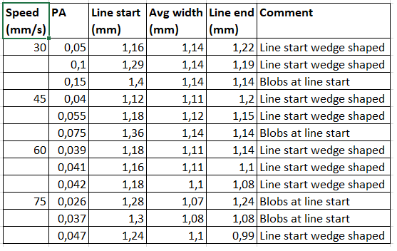
Test results (from initial testing using symmetric PA only):
Discussion on implementation of PA formula
The results of the testing show that even if the width at the start of a print line can be tuned to the correct width it is always followed by a thinning of the line which then gradually thickens out again until it reaches the full line width some distance further around the arc of the test cylinder. This would seem to indicate that the extruder acceleration is switched off before the output velocity of the molten plastic from the nozzle outlet has reached the velocity of the filament input into the melt chamber and therefore lags the required velocity for some time before finally catching up.
The same phenomenon (but relating to the deceleration PA) can also be observed at the start of the line where it follows immediately after the end of the previous line. It seems that the extruder deceleration is switched off before the output velocity from the nozzle reaches zero, meaning that the pressure decay in the nozzle does not allow zero pressure to be reached at the end of the line. Even if a Slicer retract is done at the end of the line. then this residual pressure remaining in the nozzle is immediately restored after the unretract resulting in excess pressure at the line start with resultant blobbing.
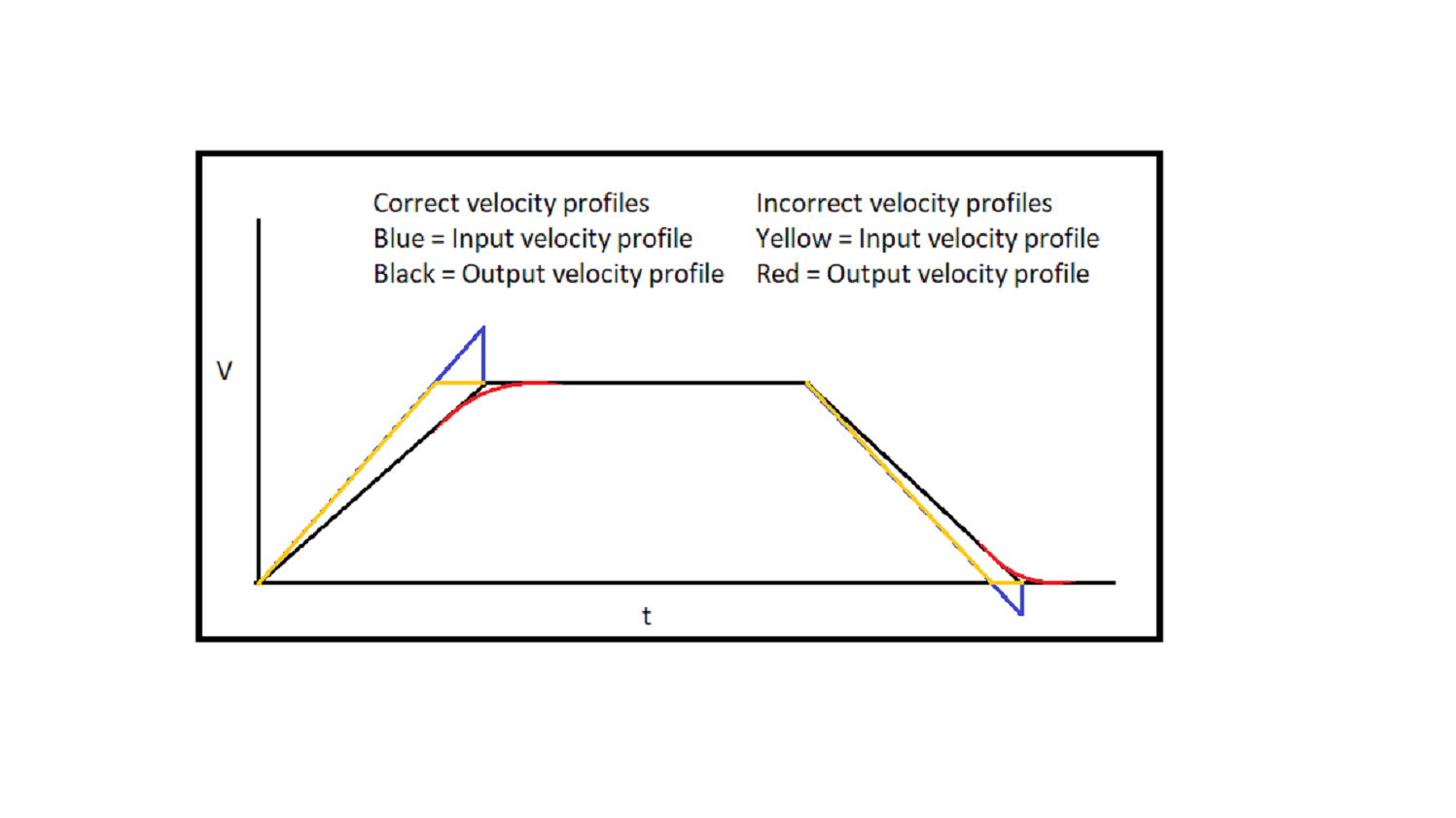
I have prepared an input vs output velocity graph indicating what seems to be happening vs what should be happening.
Note : The sloped yellow line overlaps with the first part of the blue line. The black and red lines partially overlap also.
Lastly if I calculate an actual extrusion velocity using the PA formula with a PA value of only 0.15 together with an extruder acceleration of 1750mm/s^2 and a requested extrusion speed of 2.5mm/s then the actual extrusion velocity would have to be 265mm/s which the extruder could obviously never reach. The acceleration phase therefore clearly has to be stopped well before this velocity would be reached and I am guessing that it is stopped as soon as the requested velocity (2.5mm/s in this example) is reached. This has the effect of using a higher acceleration rate than would be used without the PA but at the same time causes the acceleration to be terminated too early.
The correct application of the PA formula I believe would be to apply the new effective acceleration rate calculated by the formula over the same time interval as the original acceleration rate would have required. This would also equal the time interval required for the positional axis to reach its required speed. This would ensure that output acceleration continues at a constant rate until the required speed is reached, without lagging behind the requirement. The same argument goes for the deceleration except that a negative input velocity would be required at the end of the acceleration phase.
Line starts :
One further important discovery I made relates to the way the start of the print line is handled. The extruder and positional axis start moving simultaneously at the start of the line but at this point the plastic is at the level of the end of the nozzle, which is up in the air. This is incorrect as enough plastic would have to be at the level of the build plate by the time that movement of any axis starts. In order to ensure that the correct amount of plastic is extruded at the start of the print loop/line an initial amount must be extruded, equal to a volume made up of the height of the layer and a diameter equal to the width of the line being printed. Unless this is taken care of, the start of any print line is always wedge shaped (when PA is being used). In order to correct this, an extra extrusion start distance must be used before the axis starts to move. I was able to compensate for this by defining an extra restart distance in S3D. In this manner I was able to eliminate this problem and line starts became parallel.
Important observation regarding slicing
Furthermore after examining the G Code from the S3d slicer I noticed that in any closed loop the start and end of the loop are 100% coincident meaning that there is an overlap leading to excess plastic being deposited in this junction. This excess plastic is not related to PA factors. This slicing problem can be sort of taken care of by setting up coasting at the end of the line so as to control the amount of overlap that will occur between the start and end of the line. This is however not ideal as it will result in open ended lines being cut short by the amount of coasting set up. A better way to do that would be for the slicer to have a setting which allows for overlap to be specified on closed loops. I am not sure how other slicers print the start end junction of a print loop.
 The only reason I am bringing up retraction (and more specifically negative extra restart distance when doing retractions) is because of the role that will play in trying to assess optimal PA factors and the PA factor in turn then would play a major role in limiting bulging at corners. The retraction settings mentioned before therefore end up playing only an indirect role in determining what can happen at corners. What I am aiming at is to try to get to the highest possible PA factor that will allow proper printing of infill but also produce the greatest reduction of bulging at corners.