@dc42 Great, thank you!
Posts made by ww1g16
-
"Connecting a spindle" shared ground queryposted in CNC
Hey,
I'm just looking for some clarification on something mentioned on the following page.
https://docs.duet3d.com/User_manual/Machine_configuration/Configuration_CNC
Under the "Connecting a spindle" section, it says the following:
The ones with the square blue PCB have a design flaw (uses an opto isolator, but the input and output grounds are connected together) and should be avoided because (a) they are more difficult to drive from some Duets, and (b) sharing a direct ground connection between a Duet and a high powered brushless motor controller is a bad idea.
When wiring the suggested green board (e.g. this), you have a PWM input (DIN+ and DIN-), power input (12-30V, GND1) and an analog output (A0, GND2). In my particular scenario, I've connected the PWM-to-analog module to my 6XD via the VFD header, with this wiring
PWM-to-analog-module.DIN- to 6XD.VFD-header.GND
PWM-to-analog-module.DIN+ to 6XD.VFD-header.VFDPWM-to-analog-module.GND2 to VFD.GND
PWM-to-analog-module.A0 to VFD.VI1The VFD I'm using is the YL620-A (a Huanyang 2.2kW clone), which happens to have a 13V output which I think I can use for the power input (12V-30V and GND1) to the PWM-to-analog board. But when it comes to keeping things as isolated from the Duet as possible, is it better to power the PWM-to-analog board via the VFD, or via the 24V DC power supply used for the Duet?
e.g. option 1
PWM-to-analog-module.12-30V to VFD.13V
PWM-to-analog-module.GND1 to VFD.GNDe.g. option 2
PWM-to-analog-module.12-30V to DUET_24V_POWER_SUPPLY.24V
PWM-to-analog-module.GND1 to DUET_24V_POWER_SUPPLY.GNDI think the answer would depend on whether GND1 and GND2 are connected on these modules, and whether either/both of them is isolated from DIN-.
From the quoted section, do I interpret that as DIN- is isolated from both GND1 and GND2 on these green boards, and GND1 and GND2 are not necessarily isolated from each other? In which case, it'd be best to power the PWM-to-analog module from the VFD's 13V and GND.
Alternatively, does the quoted section mean that both the PWM input and Power input have a common ground (DIN- and GND1), which itself is isolated from GND2?
Appreciate any input!
Regards,
Will
-
RE: [3.5.0-rc.3] M122 causing Lost connection to Duet (Timeoutposted in DSF Development
@timschneider Unsure whether or not this helps track anything down, but whilst debugging some networking issues I was having whilst using 3.5.0-rc.2 I noticed that I've got StuckInSpinLoop being reported by M122. Having not looked at the git diff between rc.2 and rc.3, I'm unsure whether the section you mention has had any changes that would also be present in rc.2. If not, disregard my comment as irrelevant.
=== Platform ===
Last reset 03:05:28 ago, cause: software
Last software reset at 2024-02-02 12:31, reason: StuckInSpinLoop, Platform spinning, available RAM 13156, slot 2
Software reset code 0x4080 HFSR 0x00000000 CFSR 0x00000000 ICSR 0x0041f80f BFAR 0xe000ed38 SP 0x200027e0 Task NETW Freestk 4294966993 ok
Stack: fffffdff 00000000 00000000 00000009 00429eed 0040c6ef 0040c71e 41000000 0040c4cd 3f317200 b5dda462 388ab355 bb360b61 3e2aaaab 20004bbc 00000000 fd93463c a5a5a5a5 a5a5a5a5 a5a5a5a5 0040da6b 20004bbc a5a5a5a5 a5a5a5a5 00410441 a5a5a5a5 0045db95
Error status: 0x04
MCU temperature: min 25.8, current 26.4, max 29.0
Supply voltage: min 24.5, current 24.6, max 25.0, under voltage events: 0, over voltage events: 0, power good: yes
Heap OK, handles allocated/used 0/0, heap memory allocated/used/recyclable 0/0/0, gc cycles 0
Events: 0 queued, 0 completed
Driver 0: standstill, SG min n/a
Driver 1: standstill, SG min n/a
Driver 2: standstill, SG min n/a
Driver 3: standstill, SG min n/a
Driver 4: standstill, SG min n/a
Driver 5:
Driver 6:
Driver 7:
Driver 8:
Driver 9:
Driver 10:
Driver 11:
Date/time: 2024-02-02 15:36:48
Cache data hit count 4294967295
Slowest loop: 11.13ms; fastest: 0.20ms
I2C nak errors 0, send timeouts 0, receive timeouts 0, finishTimeouts 0, resets 0
Duet 2 WiFi 2WiFi 3.5.0-rc.2 Duet WiFi Server n/a 2.1beta6 Duet Web Control DWC 3.5.0-rc.2 -
RE: CNC style Pendantposted in Hardware wishlist
This thread was useful when debugging some issues I was having using this exact pendant with the Arduino Nano as the microcontroller. I'm not making use of the PanelDue passthrough, just the pendant straight to a Duet3 6XD. For some reason when using the resistors rather than a level shifter on TX to bring it down to 3.3V, I was having issues with awful noise between the 6K8 resistor and the Duet 3, both when transmitting anything on TX and when just sitting idle at 5V. The resistor was on the pendant side of the long cable, and the noise was present on both the Duet and pendant sides. I spent a while figuring out what I'd done wrong but wound up using a level shifter (can't find a receipt but it looks the same as the 4 channel variant here) on the Duet side instead and that worked.
Perhaps it was due to me leaving the Nano unmodified, but my interpretation of the instructions here was that that was only necessary when using the PanelDue passthrough.
-
RE: "...bad header format code was received (0xff)"posted in Firmware installation
@chrishamm Update now that the new ribbon cables have arrived, unfortunately still the same issue. To ensure there were no remnants from before, I repeated the steps from before: set it up in standalone mode (all okay), updated the firmware, removed the SD card from Duet, installed a fresh copy of DuetPi, and then went through the setup process on the Pi 4. But I'm still seeing the same warnings/error messages as posted above. I'll go ahead and email warranty@duet3d.com as suggested.

UPDATE: Email now sent
-
RE: "...bad header format code was received (0xff)"posted in Firmware installation
@chrishamm Yup certainly. I'll get a couple ordered to give them a go, and then get back to you

-
RE: "...bad header format code was received (0xff)"posted in Firmware installation
Here is the output of both of those commands, with 'upgrade' still running but after 30 mins of waiting at this stage, it look to have gotten stuck again at 'Setting up reprapfirmware (3.4.3-1)'. I've got to head out for a while, so I'll leave it running.
sudo_apt_get_update.txt
sudo_apt_get_upgrade.txtTrying to navigate to DWC whilst that's going on results in:
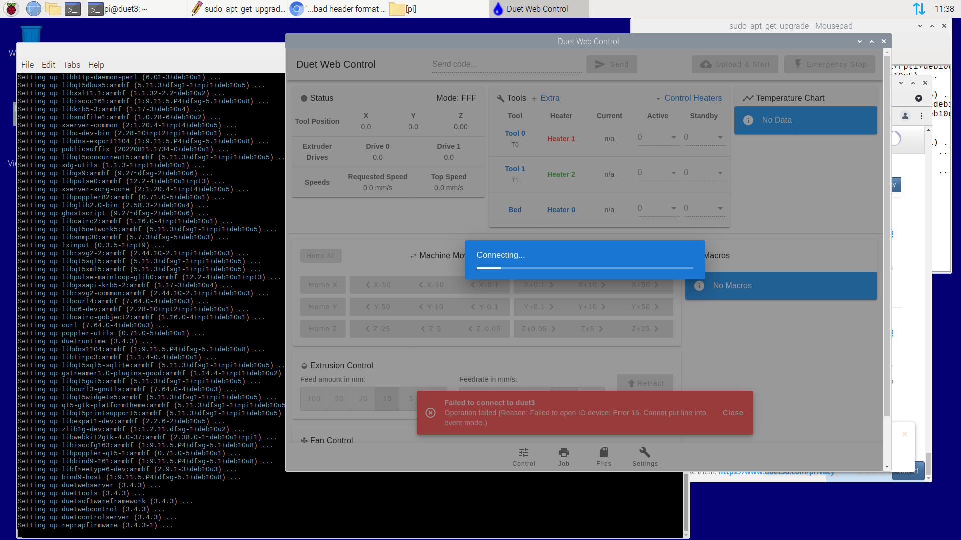
"Failed to open IO device: Error 16. Cannot put line into event mode."
-
RE: "...bad header format code was received (0xff)"posted in Firmware installation
Certaintly. So just to record the order of operations I'm going through:
- Flash A2 SD card with DuetPi from https://pkg.duet3d.com/DuetPi.zip using BalenaEtcher
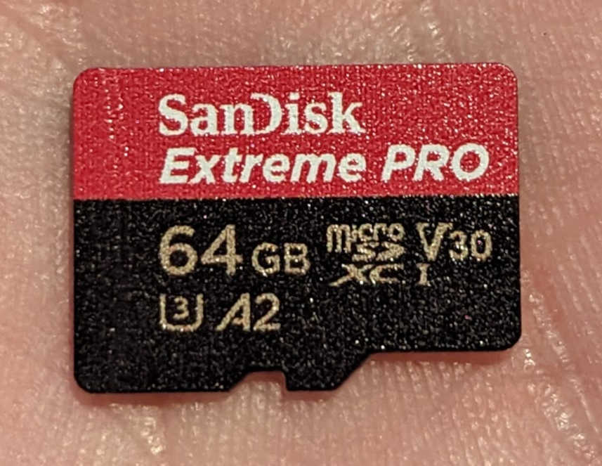 , setup wpa_supplicant
 - Add just flashed SD card to Pi4, remove the working card we just setup from the 6XD
- Pi4 and 6XD connected with ribbon cable
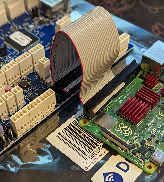
- Official USB C 5V3A power supply to Pi, generic USB C power supply to 6XD from a separate charger, default "Int 5V EN" jumper installed (all others not present)
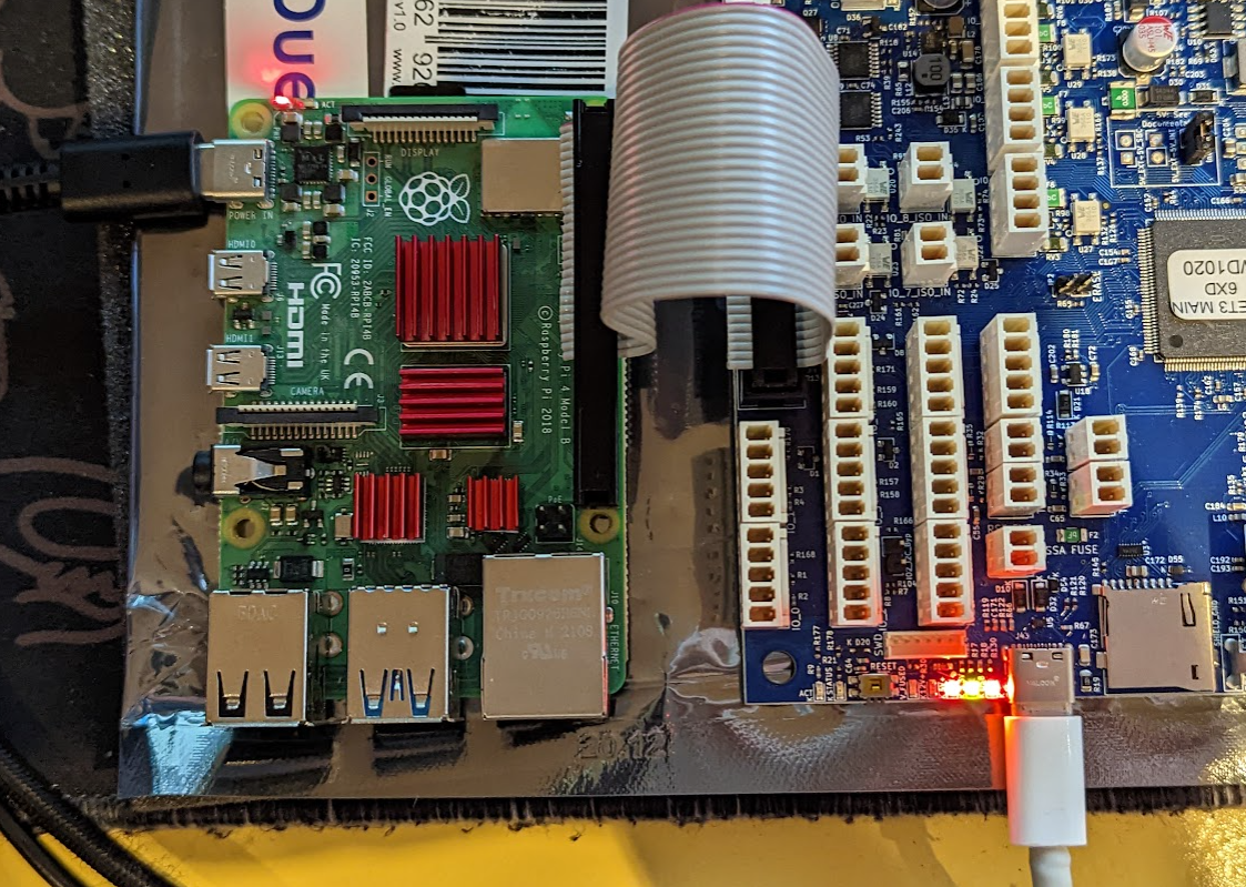
- Power on both, don't change anything else and just wait until duet3.local goes live
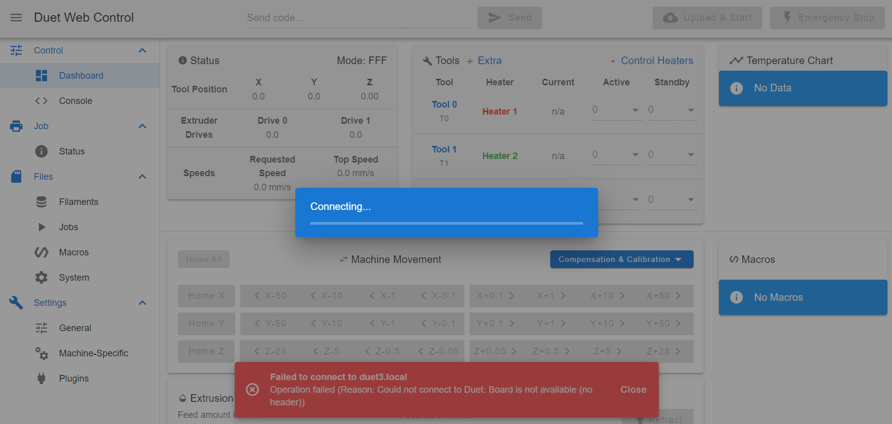
I can't get any further through DWC because of this 'Connecting...' window, but in the background you can see a mention of "Could not connect to Duet: Board is not available (no header))"
- Remove power from Pi4, plug in HDMI, reconnect power to Pi4
- Going through setup menu for language, wifi, etc, but pressing SKIP to downloading updates as that previously ended up never finishing.
- Running sudo journalctl -u duetcontrolserver
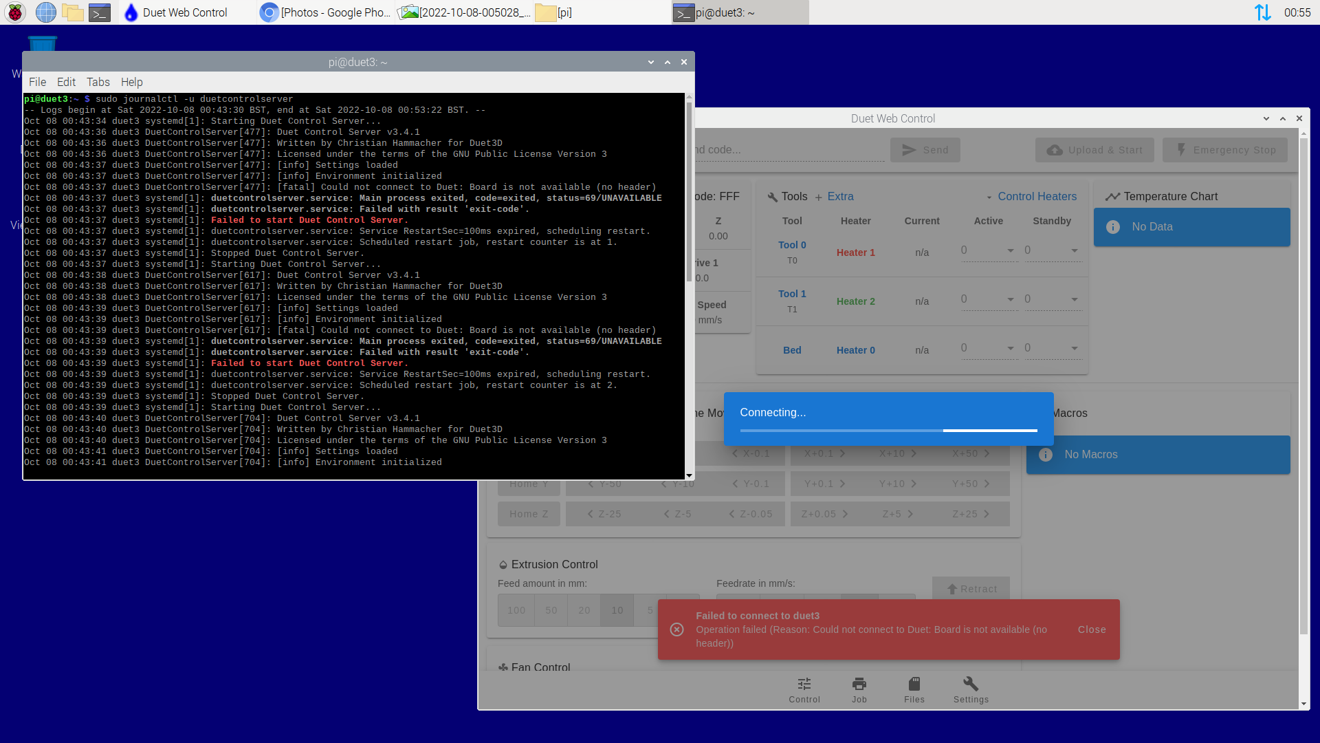
- Flash A2 SD card with DuetPi from https://pkg.duet3d.com/DuetPi.zip using BalenaEtcher
-
RE: "...bad header format code was received (0xff)"posted in Firmware installation
@phaedrux Thanks for the suggestion! I've gone ahead and set up the 6XD in standalone mode, and everything seems to have worked as expected. I'm able to connect via web interface, and all is looking like my other duet boards


I've also updated to the latest 3.4.3 release using Duet2and3Firmware-3.4.3.zip just to make sure everything is on the same page.
I've included the output of M122 below in case it becomes useful. How do you suggest I begin bringing the SBC back into the picture?
(excuse the heater faults, this is just a barebones config.g from the configurator and nothing is plugged into the 6XD other than USB and Ethernet)
M122 === Diagnostics === RepRapFirmware for Duet 3 MB6XD version 3.4.3 (2022-10-05 09:07:12) running on Duet 3 MB6XD v1.0 or later (standalone mode) Board ID: 08DLM-956DA-M2NS4-6J9DA-3S86Q-KA3LT Used output buffers: 1 of 40 (13 max) === RTOS === Static ram: 151256 Dynamic ram: 96076 of which 0 recycled Never used RAM 103340, free system stack 206 words Tasks: NETWORK(ready,37.9%,227) ETHERNET(notifyWait,0.2%,423) HEAT(notifyWait,0.0%,360) Move(notifyWait,0.0%,351) CanReceiv(notifyWait,0.0%,943) CanSender(notifyWait,0.0%,335) CanClock(delaying,0.0%,343) MAIN(running,61.7%,1127) IDLE(ready,0.2%,29), total 100.0% Owned mutexes: === Platform === Last reset 00:01:26 ago, cause: software Last software reset at 2022-10-07 22:31, reason: User, GCodes spinning, available RAM 102148, slot 0 Software reset code 0x0003 HFSR 0x00000000 CFSR 0x00000000 ICSR 0x00400000 BFAR 0x00000000 SP 0x00000000 Task MAIN Freestk 0 n/a Error status: 0x00 Step timer max interval 1754 MCU temperature: min 33.0, current 34.9, max 35.2 Supply voltage: min 0.2, current 0.2, max 0.3, under voltage events: 0, over voltage events: 0, power good: yes 12V rail voltage: min 0.1, current 0.2, max 0.3, under voltage events: 0 Heap OK, handles allocated/used 0/0, heap memory allocated/used/recyclable 0/0/0, gc cycles 0 Events: 1 queued, 1 completed Driver 0: ok Driver 1: ok Driver 2: ok Driver 3: ok Driver 4: ok Driver 5: ok Date/time: 2022-10-07 22:48:12 Slowest loop: 10.91ms; fastest: 0.05ms === Storage === Free file entries: 10 SD card 0 detected, interface speed: 25.0MBytes/sec SD card longest read time 2.4ms, write time 0.0ms, max retries 0 === Move === DMs created 125, segments created 0, maxWait 0ms, bed compensation in use: none, comp offset 0.000 === MainDDARing === Scheduled moves 0, completed 0, hiccups 0, stepErrors 0, LaErrors 0, Underruns [0, 0, 0], CDDA state -1 === AuxDDARing === Scheduled moves 0, completed 0, hiccups 0, stepErrors 0, LaErrors 0, Underruns [0, 0, 0], CDDA state -1 === Heat === Bed heaters 0 -1 -1 -1 -1 -1 -1 -1 -1 -1 -1 -1, chamber heaters -1 -1 -1 -1, ordering errs 0 === GCodes === Segments left: 0 Movement lock held by null HTTP is idle in state(s) 0 Telnet is idle in state(s) 0 File is idle in state(s) 0 USB is idle in state(s) 0 Aux is idle in state(s) 0 Trigger is idle in state(s) 0 Queue is idle in state(s) 0 LCD is idle in state(s) 0 SBC is idle in state(s) 0 Daemon is idle in state(s) 0 Aux2 is idle in state(s) 0 Autopause is idle in state(s) 0 Code queue is empty === CAN === Messages queued 778, received 0, lost 0, boc 0 Longest wait 0ms for reply type 0, peak Tx sync delay 0, free buffers 50 (min 50), ts 433/0/0 Tx timeouts 0,0,432,0,0,344 last cancelled message type 4514 dest 127 === Network === Slowest loop: 10.91ms; fastest: 0.03ms Responder states: HTTP(0) HTTP(0) HTTP(0) HTTP(0) HTTP(0) HTTP(0) FTP(0) Telnet(0), 0 sessions Telnet(0), 0 sessions HTTP sessions: 1 of 8 = Ethernet = State: active Error counts: 0 0 0 1 0 0 Socket states: 5 2 2 2 2 0 0 0 === Multicast handler === Responder is inactive, messages processed 0 -
RE: "...bad header format code was received (0xff)"posted in Firmware installation
GPIO continuity
Tested all listed GPIO pins, and all come back as 0Ω
gpioget gpiochip0 25
With 3.3V connected to TfrRdy, returns 1
When disconnected, returns 0Seems as expected
spidev_test.c
"./spidev_test -D /dev/spidev0.0" returns
spi mode: 4
bits per word: 8
max speed: 500000 Hz (500 KHz)

FF FF FF FF FF FF
40 00 00 00 00 95
FF FF FF FF FF FF
FF FF FF FF FF FF
FF FF FF FF FF FF
DE AD BE EF BA AD
F0 0D
Seems as expected, minus spi mode:4 but I found https://forums.raspberrypi.com/viewtopic.php?t=298486 which seems to suggest the following:
Set Get
0 4
1 5
2 6
3 7 -
RE: "...bad header format code was received (0xff)"posted in Firmware installation
I've just found some additional debugging instructions here:
https://github.com/Duet3D/DuetSoftwareFramework/wiki/SBC-Setup-Guide#troubleshooting
So please hold on until I've attempted these first as I don't want to waste anyone's time
-
RE: "...bad header format code was received (0xff)"posted in Firmware installation
I also should have prefaced all this with the hardware, which is the Duet 3 6XD connected to a raspberry RPI 4 with the supplied header cable
-
"...bad header format code was received (0xff)"posted in Firmware installation
Versions:
duetcontrolserver - 3.4.3
duetpimanagementplugin - 3.4.3
duetpluginservice - 3.4.3
duetruntime - .3.4.3
duetsd - 1.1.0
duetsoftwareframework - 3.4.3
duettools - 3.4.3
duetwebcontrol - 3.4.3
duetwebserver - 3.4.3Describe exactly how to recreate the problem.
This was during the first time setup of the board. I was going through https://docs.duet3d.com/User_manual/Machine_configuration/SBC_setup and after section "4. First Boot", I could connect to Duet Web Control but immediately got an error saying it failed to connect to Duet. I kept going to see if updating the firmware would resolve it, as I'm still able to ssh to the pi. During "6. Update firmware", the update reached 96% before getting no further - I left it overnight in case it was just slow, but no change the next day. At this point I restarted both the pi and Duet and began troubleshootingHow things are connected:


Error messages:
Output of connecting to duet via browser (e.g. 192.168.0.X)
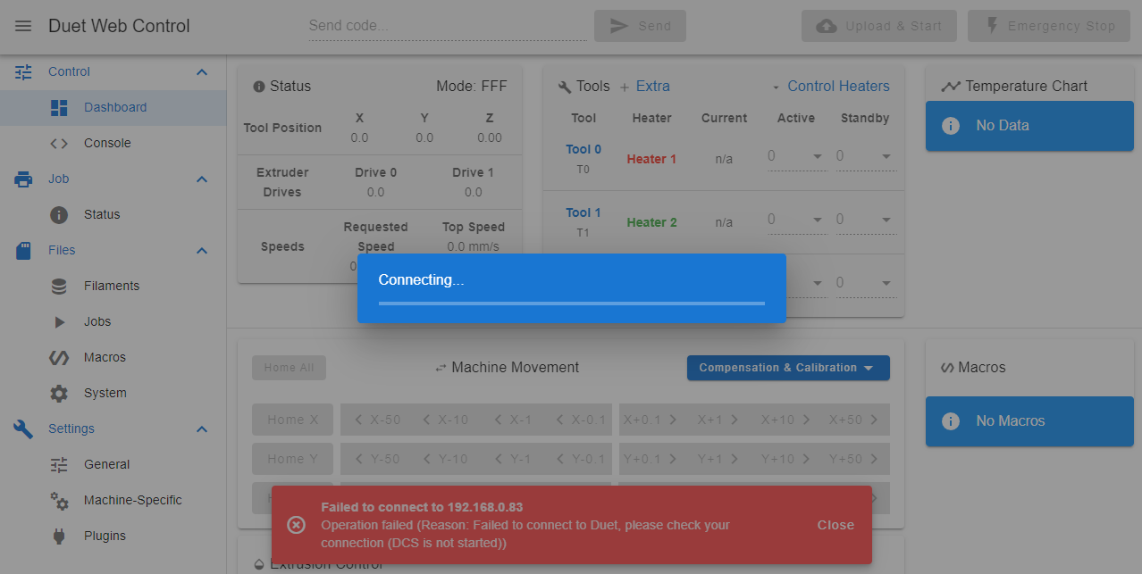
Output of "sudo systemctl start duetcontrolserver"

Output of "systemctl status duetcontrolserver.service"

Output of "sudo journalctl -u duetcontrolserver"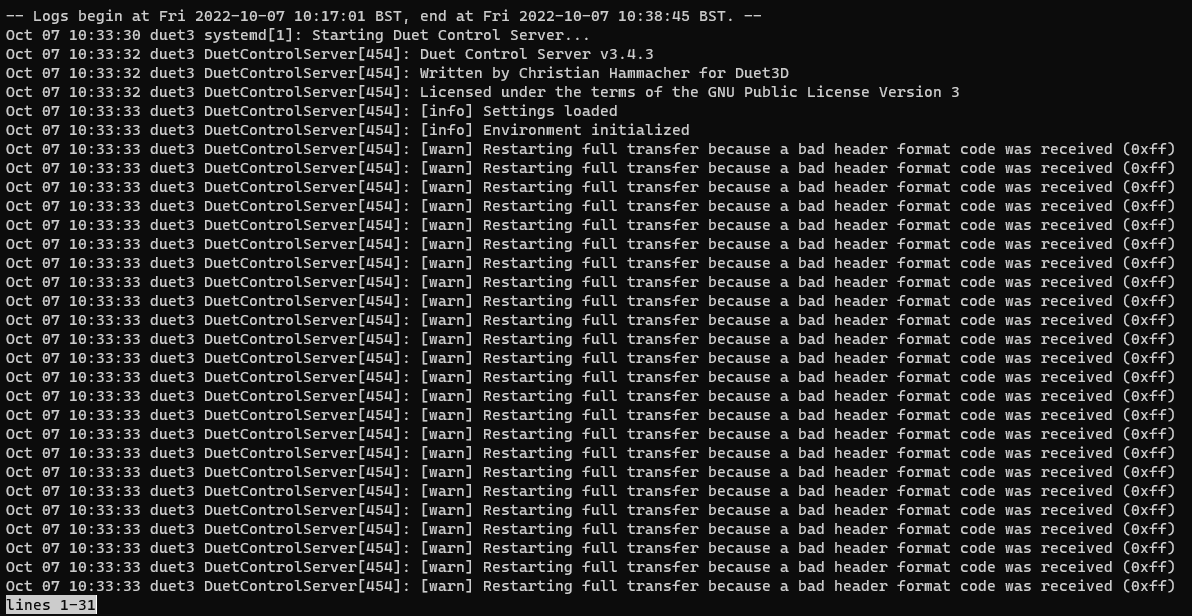
What I've tried so far:
Included SD card
New SD card
Changing Pi
Reseating ribbon cable
Updating firmware via apt-get
Updating firmware via Bossa
I noticed two SPI devices (spidev0.0 and spidev0.1), so tried editing /opt/dsf/conf/config.json to use spidev0.1 instead of the default spidev0.0, but that returns a different error which I believe would imply 0.0 is correct (0.0 returns DCS is not started, 0.1 returned something to do with enable pin) -
Improved homing macrosposted in Gcode meta commands
Morning all!
Just thought I'd share a macro that has saved me a lot of time since implementing it. It's for homing x and y taking advantage of the axis measuring feature to detect if sensorless homing on any axis was bad (triggered too early). I use sensorless homing on a CoreXY and it can be a bit finicky over time and sometimes give me vastly incorrect homing. With these new homing macros for X and Y, both axes are measured and compared to their set length. It's likely not going to be a drop-in replacement for your own machines, but perhaps something similar could be useful.
Normal homing behaviour for me:
- Bump Xmax
- Bump Ymax
- Wait at Xmax, Ymax to proceed with other start gcode
New homing behaviour:
- Bump Xmin
- Measure distance to Xmax. If shorter than expected (aka bump Xmin triggered too early, or travel to Xmax stopped too early), abort if unable to home after n retries
- Bump Ymin
- Measure distance to Y max. If shorter than expected (aka bump Ymin triggered too early, or travel to Ymax stopped too early), abort if unable to home after n retries
One note to add is that this of course requires either an endstop at both min and max of both axis, or something to bump against at both ends if using sensorless. This meant for me I had to add something to bump against at Ymin, otherwise my print head would be the first thing to crash into the front of my corexy.
Hope it's useful!
(note, comments in the code are outdated so take them with a pinch of salt)
; homex.g
; called to home the X axis

;G1 Xnnn Ynnn Znnn H0	Ignore endstops while moving.
;G1 Xnnn Ynnn Znnn H1	Sense endstops while moving (ignoring the axis limits).
;G1 Xnnn Ynnn Znnn H2	Ignore endstops while moving. Also ignore if axis has not been homed. On Delta and Core XY, axis letters refer to individual towers.
;G1 Xnnn Ynnn Znnn H3	Sense endstops while measuring axis length, setting the appropriate M208 limit to the measured position at which the endstop switch triggers.

M400				; Make sure everything stops

var x_backoff = 10
var x_max = move.axes[0].max
var x_min = move.axes[0].min
var x_length = var.x_max - var.x_min

M566 X50.00 Y50.00     			; Set maximum instantaneous speed changes (mm/min)
M201 X500.00 Y500.00      		; Set accelerations (mm/s^2)
M913 X50 Y50    ; Set current for X axis to 60% of normal value
M915 X Y S2     ; 0 is too sensitive, 4 isnt sensitive enough.

G91              		; relative positioning
G1 H2 Z5 F{60*60}   	; Lift Z a little.

while true
	if iterations = 20
		M18 X
		G1 H2 Z-5 F{60*60}  ; lower Z again
		G90              ; absolute positioning
		M913 X100 Y100		; Reset motor currents
		M98 P"0:/macros/Parameters"
		abort "Too many auto calibration attempts"
	M574 X1 S4              ; Set endstop configuration: low end on X (1), single motor load detection (3)
	G1 H1 X-999 F{60*60} 	; Move to X_min
	G1 H0 X{var.x_backoff} F{60*60} 		; Back off a little

	M574 X2 S4              ; Set endstop configuration: low end on X (1), single motor load detection (3)
	G1 H3 X999 F{60*60} 	; Move to X_max, set x measured length
	G1 H0 X{-var.x_backoff} F{60*60} 	; Back off a little

	var x_measured_length = move.axes[0].max - move.axes[0].min

	echo {"Set length: " ^ var.x_length ^ "mm"}
	echo {"Measured length: " ^ var.x_measured_length ^ "mm"}
	M208 X{var.x_min}:{var.x_max}
	if var.x_measured_length >= var.x_length
		G92 X{var.x_max-var.x_backoff}
		break
	echo "Repeating homing, axis length is too low. Measured (" ^ var.x_measured_length ^ "mm) < Set (" ^ var.x_length ^ "mm)"
	G4 S1
echo "X Homing Successful"

G1 H2 Z-5 F{60*60}  ; lower Z again
G90              ; absolute positioning
M913 X100 Y100		; Reset motor currents
M98 P"0:/macros/Parameters"
; homey.g ; called to home the Y axis ;G1 Xnnn Ynnn Znnn H0 Ignore endstops while moving. ;G1 Xnnn Ynnn Znnn H1 Sense endstops while moving (ignoring the axis limits). ;G1 Xnnn Ynnn Znnn H2 Ignore endstops while moving. Also ignore if axis has not been homed. On Delta and Core XY, axis letters refer to individual towers. ;G1 Xnnn Ynnn Znnn H3 Sense endstops while measuring axis length, setting the appropriate M208 limit to the measured position at which the endstop switch triggers. M400 ; Make sure everything stops var y_backoff = 10 var y_max = move.axes[1].max var y_min = move.axes[1].min var y_length = var.y_max - var.y_min M566 X50.00 Y50.00 ; Set maximum instantaneous speed changes (mm/min) M201 X500.00 Y500.00 ; Set accelerations (mm/s^2) M913 X50 Y50 ; Set current for X axis to 60% of normal value M915 X Y S2 ; 0 is too sensitive, 4 isnt sensitive enough. G91 ; relative positioning G1 H2 Z5 F{60*60} ; Lift Z a little. while true if iterations = 20 M18 Y G1 H2 Z-5 F{60*60} ; lower Z again G90 ; absolute positioning M913 X100 Y100 ; Reset motor currents M98 P"0:/macros/Parameters" abort "Too many auto calibration attempts" M574 Y1 S4 ; Set endstop configuration: low end on X (1), single motor load detection (3) G1 H1 Y-999 F{60*60} ; Move to X_min G1 H0 Y{var.y_backoff} F{60*60} ; Back off a little M574 Y2 S4 ; Set endstop configuration: low end on X (1), single motor load detection (3) G1 H3 Y999 F{60*60} ; Move to X_max, set x measured length G1 H0 Y{-var.y_backoff} F{60*60} ; Back off a little var y_measured_length = move.axes[1].max - move.axes[1].min echo {"Set length: " ^ var.y_length ^ "mm"} echo {"Measured length: " ^ var.y_measured_length ^ "mm"} M208 Y{var.y_min}:{var.y_max} if var.y_measured_length >= var.y_length G92 Y{var.y_max-var.y_backoff} break echo "Repeating homing, axis length is too low. Measured (" ^ var.y_measured_length ^ "mm) < Set (" ^ var.y_length ^ "mm)" G4 S1 echo "Y Homing Successful" G1 H2 Z-5 F{60*60} ; lower Z again G90 ; absolute positioning M913 X100 Y100 ; Reset motor currents M98 P"0:/macros/Parameters" -
RE: M486 does not list all objects and M486 C does not workposted in General Discussion
Having seen a lot of the work that has been done with the gcode viewer, I don't think being able to see the part names for all of the parts is too essential. I know this is only in my use case, but despite having up to around 180 parts they are all the same part so storing the name for all of them isn't necessary. Alas all our machines are on Duet 2 Wifi's though - so am I right in thinking this would definitely need to be Duet 3 and above?
-
RE: M486 does not list all objects and M486 C does not workposted in General Discussion
Reviving an old thread, apologies!
We're coming across this same issue on our print farm. Our use case is normally printing the same small part around 50-80 times on a print bed, and we recently moved to incorporate object labelling to our gcode from PrusaSlicer. Only came across the 10 object issue during preliminary testing, and then found this forum thread. Is there any planned increase of this object limit? By what means I don't know, others seem to have made some suggestions about storing information on the SD card - is this feasible?
-
Duet Smart Effector (PCB rev 2.0) - Replacement capacitor (C1)posted in Duet Hardware and wiring
Hardware - Duet3D SmartEffector (PCB rev 2.0)
Relevant files - SmartEffector_schematic_v2.0.pdfHi,
I'm not sure whether this is the cause of a problem I've been having (doubt it) or a result of me being too heavy handed during some disassembly, but the capacitor labelled C1 is damaged/missing.

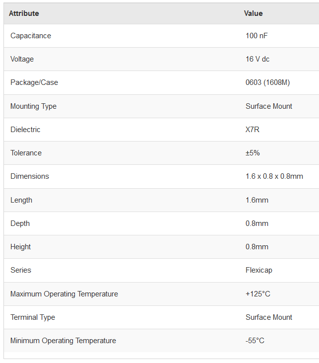
I'm looking to purchase a replacement, and have narrowed it down from the schematics to a 100nF C0603 capacitor. On googling this, however, I realise there are a lot of different types of this...
 Are there any specific ratings I should be looking for? I see it's between 3.3V and GND so I assume it's just removing high frequency noise. Is something like this suitable? (If you're having any trouble viewing the link, I've attached an image of the specs as well)
-
Slic3r Prusa Edition Duet Uploadposted in General Discussion
Hey,
Following the latest release from Prusa, they've added support to upload/print to a Duet board from the slicer itself. However, I'm getting the following error code...

I don't know whether this is a problem with my DuetWifi firmware or the slicer (hence why I'm asking on this forum rather than the Prusa forum!). Any suggestions?
Duet 2 Wifi
Firmware Name: RepRapFirmware for Duet 2 WiFi/Ethernet
Firmware Electronics: Duet WiFi 1.02 or later
Firmware Version: 2.01(RTOS) (2018-07-26b2)
WiFi Server Version: 1.21
Web Interface Version: 1.21.2-dc42
CoreXY