Duet3D magnetic filament sensor wiring confusion
-
Setting up a new magnetic filament sensor. Going by documentation diagram, one assumes the diagram is of the component side of the board. We received the sensor fully assembled and don't to disassemble to verify that.
If the diagram is correct, then the connector is wired just opposite of the E0 connector on the Duet WiFi controller board. Yet the picture of an installed unit shows the black wire(assuming ground) and the blue wire(assuming output) installed in the same position as on the control board in relation to the guild key on the connectors.
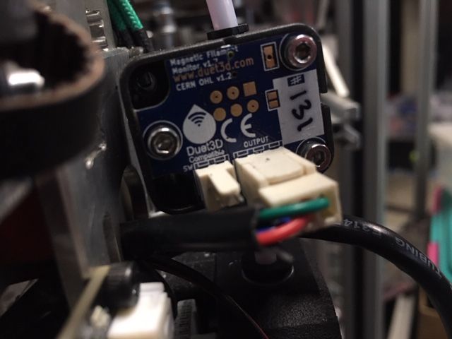
Here are pics that show what I am speaking of.

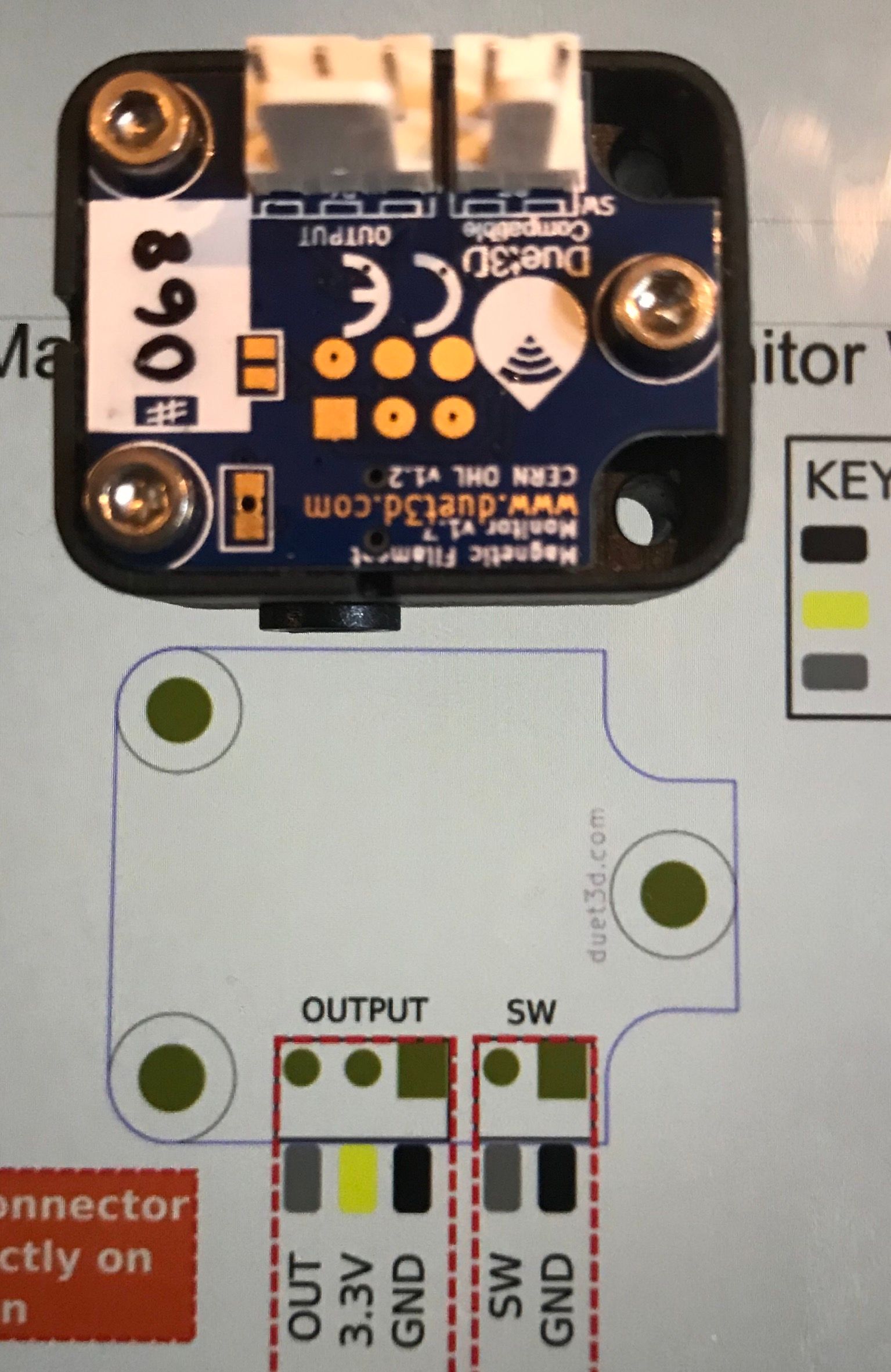
Is there a definite diagram that shows the correct wiring so that we do not destroy this new, expensive sensor.
-
The two connectors are wired 1-to-1, so placing them side by side the wires read on both of them
- Signal
- +V
- GND
from one side to the other.
-
Referring to my pic of the sensor on the diagram, the pin on the right (large square) should be pin 1.
If we wire the connector as it would mount on the sensor, the key would face down and ground would still be on the right with the signal on the left.
On the Duet 2wifi control board those inputs are opposite that. That is viewing the control board with the key tab on E0 stop connector again pointing down, the ground is on the left and the signal is on the right.
So a 1 to 1 wiring would not be what the sensor diagram is showing. It would be what the pic of the installed unit is showing if my assumptions of the wire colors are correct. Ground on the left and signal on the right.
If by placing the wire connectors wiring end to wiring end and connecting the cable straight across, it would match the sensor diagram and the wifi control board, but that would be 1 to 3, 2 to 2 and 3 to 1 connection.
Forgive me if I’m being a little thick here, but it has been a long 6 day week and I haven't recovered quite yet. -
Well, as far as "what-is-what" is concerned, the docs should tell you enough.
My approach does not rely on exact knowledge of the pin usages - what I really wanted to tell you:
- put both connectors equally oriented side by side
- number the pins from left to right as 1,2 and 3 respectively
- wire pin 1 on connector 1 to pin 1 on connector 2
- wire pin 2 on connector 1 to pin 2 on connector 2
- wire pin 3 on connector 1 to pin 3 on connector 2
No need to think about what the pin's usages are
")
Good luck
Andreas -
Sorry the documentation was confusing, Ihave updated it.
https://duet3d.dozuki.com/Wiki/Duet3dFilamentMonitor_RotatingMagnetVersion#Section_Wiring
The original image you have a screen shot of shows the "top" of the board which is the opposite side from the headers.
-
@DarylMcM updated again.
-
TP3Tony
Yes, the new documentation layout makes much more sense. The output pin is now next to the 2 pin switch header. The original showed the ground next to that header.Now a 1 to 1 connection between the connectors makes sense as well.
Knowing what the pin of any header is suppose to be does matter, else one might find a destroyed accessory or worse yet a very expensive control board. -
@DarylMcM indeed, so sorry for the confusion!
-
I just got my sensor in the mail. I still can't understand the wiring, what is the 2 pin wire lead for? Am I using both the 3 pin and the 2 pin or is it an either or thing? which do I hook up where?
-
@57buick the 2 pin lead is to connect an external switch. this is optional, generally used where the monitor is connected after the extruder:
https://duet3d.dozuki.com/Wiki/Duet3dFilamentMonitor_RotatingMagnetVersion#Section_After_the_extruderOn systems that use a bowden tube it is also possible to mount the filament monitor after the extruder. In this case filament out will not be detected until the end of the filament is in the extruder. The second two pin header on the PCB is connected a separate filament sensing switch if you want to detect filament out before the extruder, but detect movement after the extruder.
I have also updated the wiring diagram to show this is optional.
-
thanks for clarifying, one other question. Can I share the ground with my other sensors like my endstop switch and IR sensor when running thru my breakout board back to the board then split off to the various connectors? To save running extra wires to my hotend?
-
@57buick said in Duet3D magnetic filament sensor wiring confusion:
thanks for clarifying, one other question. Can I share the ground with my other sensors like my endstop switch and IR sensor when running thru my breakout board back to the board then split off to the various connectors? To save running extra wires to my hotend?
Yes, you can share the ground connection with other 3.3V ground connections such as IR Z probe and endstop switches. Note, thermistors do not use a ground connection, they use VSSA; so you can't share a thermistor wire.
-
my sesnor does not appear to work? I get no data received. I also have no lights on it when powering on or anything, it looks like no LED was soldered onto it? Is this correct? @dc42 I got it from Filastruder recently
-
@57buick I have replied on your other thread. Posting to multiple threads does not help.