Issues setting up duet wifi with dual x axis motors and endstops
-
Is your PanelDue firmware up to date too? https://duet3d.dozuki.com/Wiki/PanelDue_Firmware_update
Is the wiring, or the endstop, different on the U axis to the X axis? Because that sounds like it’s inverted, which it isn’t in config.g
In the Fans section of your config.g, the comments of the two M106 commands seemed to had a return put in, so the words “turned off” and “turned on” appear to be on new lines. Lines must start with a Gcode or a comment mark (semi colon). I doubt this will change anything, but good to tidy it up!
I am running out of ideas as to why this isn’t working. My only other suggestion would be to swap the U axis with the extruder, so move the U motor to E0, and the U endstop to E0 Endstop pins, and test if it works there.
Ian
Bed-slinger - Mini5+ WiFi/1LC | RRP Fisher v1 - D2 WiFi | Polargraph - D2 WiFi | TronXY X5S - 6HC/Roto | CNC router - 6HC | Tractus3D T1250 - D2 Eth
-
@droftarts
the paneldue is 1.21.4 -
well im done... trying to update this panel due as suggested and its been a headache and now im to mad to continue for tonight... first off the enclosure i printed from thingiverse wasnt designed with updating firmware in mind and would be to much work to disassemble.... the designer left plenty of room for the other connectors but no way to get a micro usb plug to the board.. i had to sand down my plug to skin and bones to fit in the tiny slot he left for access... then when i followed the instructions on the web link provided after downloading bossa, my panel due now only displays a black screen and its not recognising it in windows so i cant get the port to use bossa to re upload the firmware....
ill see you guys in the morning
Highly modified FT5 R1, ATX supply, mosfet w/silicone heat pad, bmg ext, TMC2600 drivers, and my custom quad z mod with 4 lead screws and custom cut new upper panels and bed, and using the dual z endstop mod. New project is 800x500x500z printer.
-
@wingtip said in Issues setting up duet wifi with dual x axis motors and endstops:
Ok... im getting frustrated here but i think we're close. So right now here are my versions now.
Firmware Name: RepRapFirmware for Duet 2 WiFi/Ethernet
Firmware Electronics: Duet WiFi 1.02 or later
Firmware Version: 2.04 (2019-11-01b1)
WiFi Server Version: 1.23
Web Interface Version: 1.21.2-dc42I also removed the Endstop line for E as mentioned. I verified the x2 endstop is in fact working and triggering when viewing the machine properties window. but im still not able to stop the x2 motor/aka U drive thats plugged into the E1 port with the enstop thats plugged into the E1 enstop port.
Looking at this image
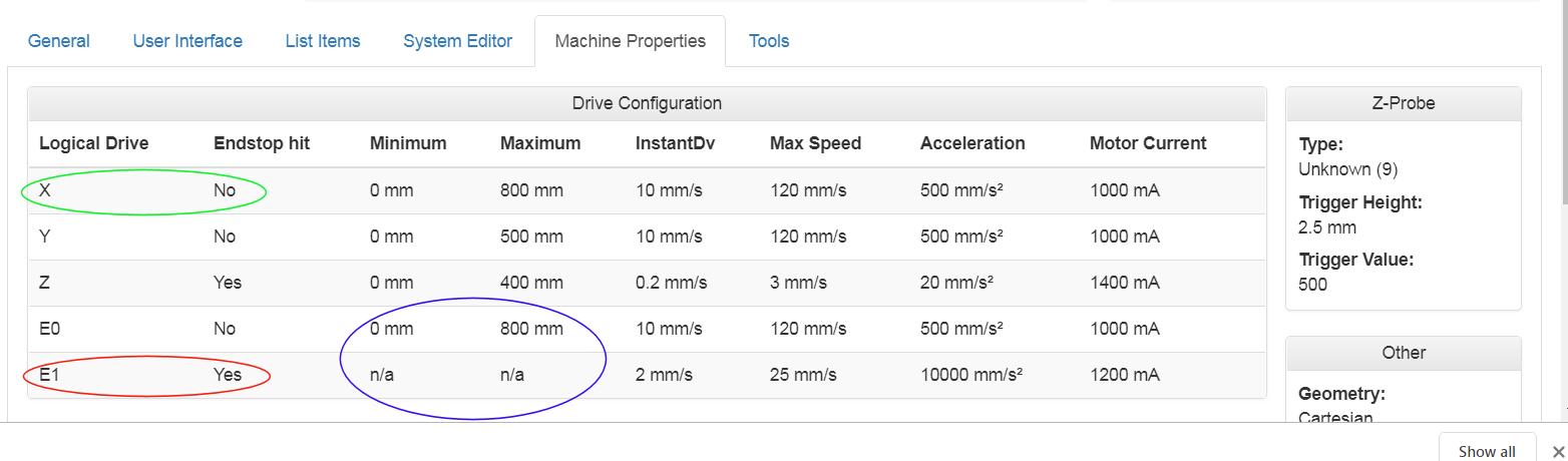
the green circle shows the x1 motor/vertical post. the motor is currently at mid travel OFF the endstop and is displaying the correct status. This motor also stops correctly when it does get to the endstop
the red circle shows the x2 motor/vertical post that is plugged into the E1 motor port which is remapped to U4. The endstop is plugged into the E1 port. the motor is currently at mid travel OFF the endstop and is displaying the wrong status but does trigger when manually activated. the problem is it still does not STOP the x2 motor/vertical post aka U4. the motor still just ignores this endstop
the blue circle has me really confused... why is my E0, aka extruder showing a min of 0 and a max of 800 while the E1, aka the x2 motor only shows n/a despite clearly being defined in the config to be min 0 and max 800???????? uggggg im brain fried
To see the U axis endstop properly, you need to make the U axis visible temporarily, by sending M584 P4.
-
good morning gents..... so after a nights rest and calming down i found another cable this morning and tried it and bam, it recognised it and gave me the port i needed and now have my panel due working again and updated to now 1.23.2.
so i went to try to home again and same issues... so in the new web control when editing it has a g code reference where before i was using some random web page... when using the reference from the webcontrol it seems to have some more updated info and i noticed this section and thought id give it a try
M574 - RepRapFirmware 3
ParametersXnnn Position of X endstop: 0 = none, 1 = low end, 2 = high end.
Ynnn Position of Y endstop: 0 = none, 1 = low end, 2 = high end.
Znnn Position of Z endstop: 0 = none, 1 = low end, 2 = high end.
P"pin_name" Defines the pin name(s) that the endstop(s) for the specified axis are connected to. Needed when S=0 or S=1.
Snnn Endstop type: 0 = active low endstop input, 1 = active high endstop input, 2 = Z probe (when used to home an axis other than Z), 3 = single motor load detection, 4 = multiple motor load detection (see Notes).
Order dependencyThis command must be later in config.g than the M584 command that creates additional axes, or axes that have multiple motors and endstops.
Usage
The M574 command has been updated to allow for more flexibility. This includes supporting axes defined with multiple motors and multiple endstops (one per motor), use of non-default endstop inputs, and re-assigning endstop inputs.
Notes
Use a separate M574 command for each axis.
New parameter P gives the pin name(s) for the endstop(s) for the specified axis. If the number of pins matches the number of motors assigned to that axis, motors will be stopped individually when their endstop switches trigger.
New endstop type S4 means use motor stall detection (like S3) but if there are multiple motors, stop each one individually as it stalls. S3 means use motor stall detection but as in RRF 2: stop all relevant motors when the first one stalls.
ExampleOld RRF_2.x code:
M574 X1 Y1 Z1 U2 S1 ; active high endstop switches, XYZ at min, U at max
New RRF_3 code:M574 X1 S1 P"xstop" ; X min active high endstop switch
M574 Y1 S1 P"ystop" ; Y min active high endstop switch
M574 Z1 S1 P"zstop" ; Z min active high endstop switch
M574 U2 S1 P"e0stop" ; U max active high endstop switch
To use two Z motors using independent homing switches, declare two Z motors in M584, then declare two pins for Z endstops in a single M574 command. ExampleM584 X0 Y1 Z2:3 E4
M574 Z1 S1 P"io2.in+io3.in" ; Z axis with two motors, individual min endstops, active high
The order of endstop switch pin names in M574 must match the order of Z motor driver numbers in M584. When homing Z, RRF_3 homes the motors of the axis at the same time, independently to their defined endstops.so i briefly experimented with this in hopes this would solve my issues but still nothing. And im still noticing the 2nd endstop is still triggered on the wrong end no matter which way you configure it... i think i need to follow the advice to swap to a different port instead of E1/drive 4 but im off to work now and i will do some more suffering after work lol....
Highly modified FT5 R1, ATX supply, mosfet w/silicone heat pad, bmg ext, TMC2600 drivers, and my custom quad z mod with 4 lead screws and custom cut new upper panels and bed, and using the dual z endstop mod. New project is 800x500x500z printer.
-
@wingtip said in Issues setting up duet wifi with dual x axis motors and endstops:
i had to sand down my plug to skin and bones to fit in the tiny slot he left for access
Sorry you're having difficulty.
Probably would have been better to modify the enclosure rather than the PanelDue, though. It sounds like you have already deleted the firmware, and the USB is not making enough of a connection on whatever remains of the USB connector. You could solder a cut off USB cable's wires direct to the PCB, on the back where the pins are accessible. I'm checking to see if there's any other way to program the PanelDue apart from via USB(edit: fixed!). Have you got a Thingiverse link to the enclosure? Worth mentioning the problem in the comments.I'm going to try and recreate your issue with the X homing today with a really simple set up (2 motors, 2 endstops and your config and homing files). I'll let you know how I get on.
Ian
Bed-slinger - Mini5+ WiFi/1LC | RRP Fisher v1 - D2 WiFi | Polargraph - D2 WiFi | TronXY X5S - 6HC/Roto | CNC router - 6HC | Tractus3D T1250 - D2 Eth
-
@wingtip said in Issues setting up duet wifi with dual x axis motors and endstops:
good morning gents..... so after a nights rest and calming down i found another cable this morning and tried it and bam, it recognised it and gave me the port i needed and now have my panel due working again and updated to now 1.23.2.
Great!
so i went to try to home again and same issues... so in the new web control when editing it has a g code reference where before i was using some random web page... when using the reference from the webcontrol it seems to have some more updated info and i noticed this section and thought id give it a try
You've probably been looking at the general reprap Gcode page https://reprap.org/wiki/G-code, which may not have the latest info on it, and has multiple versions of gcodes for how each different firmware interprets the commands! Best to use the Duet-specific one we curate: https://duet3d.dozuki.com/Wiki/Gcode. There are plenty of links in the documentation to our one, and in my posts where I've referenced gcodes!
M574 - RepRapFirmware 3
Unless you've updated your Duet firmware again, you are NOT using RRF3, you're using RRF2 v2.04. Make sure you use the correct section! https://duet3d.dozuki.com/Wiki/Gcode#Section_M574_RepRapFirmware_2_x_and_earlier
so i briefly experimented with this in hopes this would solve my issues but still nothing. And im still noticing the 2nd endstop is still triggered on the wrong end no matter which way you configure it... i think i need to follow the advice to swap to a different port instead of E1/drive 4 but im off to work now and i will do some more suffering after work lol....
Okay! I'll test your setup and see what I get.
Ian
Bed-slinger - Mini5+ WiFi/1LC | RRP Fisher v1 - D2 WiFi | Polargraph - D2 WiFi | TronXY X5S - 6HC/Roto | CNC router - 6HC | Tractus3D T1250 - D2 Eth
-
@droftarts
Ya I realized it was a different version but I was desperate and can easily change back the few lines I edited.
I look forward to your results if you use the same ports/drives and my config. -
I've had some problems with this, but the outcome seems to be to plug the U endstop into E0! This works for me, even though the motor is plugged into motor drive E1. I'll check with @dc42 why this might be! On the whole, I'd just move the whole U axis to motor driver 3 (E0).
Edit: Tested, set U to driver 3 (E0) U endstop connected to E0_ENDSTOP works. In config.g change to:
M584 X0:3 Y1 Z2 U3 E4 P3
M569 P3 S0
M569 P4 S1
Also change U4 to U3 in homing files.I think your endstops may be wired Normally Open (NO) rather than Normally Closed (NC). It says HERE that you should use the Normally Closed pins (the outer two, the three pins usually being G (Ground), NO (Normally Open) and NC (Normally Closed)) of your microswitch. It goes on to say:
... set the signal polarity to active high (S1) in the M574 command
eg yours should be:
; Endstops
M574 X1 Y1 U1 S1 ; position low, active low
M574 Z1 S2 ; set endstops controlled by probe
This should mean that:
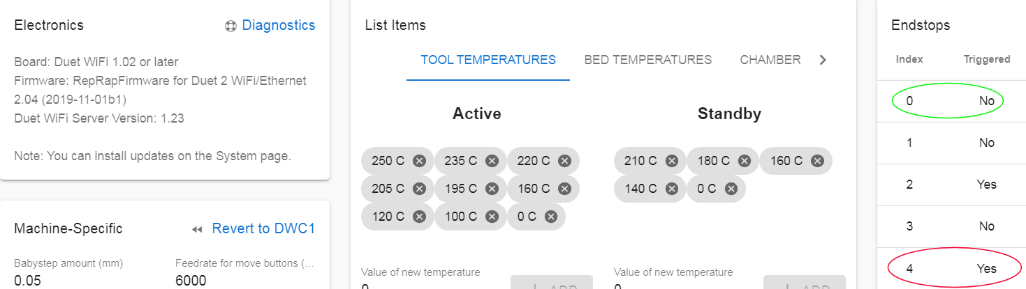
- If an endstop is not connected, the LED next to the axis motor connector will be off, and 'Triggered' will be 'Yes'
- If an endstop is connected and not triggered, the LED next to the axis motor connector will be lit, and 'Triggered' will be 'No'
- If an endstop is connected and triggered, the LED next to the axis motor connector will be off, and 'Triggered' will be 'Yes'
However, your config.g has the endstops triggering active low (M574 S0), and this seems to be shown in the endstop response. I have to invert mine with S1 to get the right response. The main thing is that all used endstops should report 'No' when not triggered, and 'Yes' when triggered!
Ian
-
I confirm, endstop switches are allocated to axes independently of stepper drivers. In RRF2 the endstop switch allocation is automatic and can't be changed. Your U axis will be allocated the first unassigned endstop, which is E0. If you created another axis such as V, that will be assigned to E1.
BTW, RRF3 handles multiple endstops on an axis automatically, without having to create additional axes.
Duet WiFi hardware designer and firmware engineer
Please do not ask me for Duet support via PM or email, use the forum
http://www.escher3d.com, https://miscsolutions.wordpress.com -
@dc42 soooooo are you saying for us mere mortals that i can leave the motor in its current connection in the E1/dr 4 slot but i just need to move the endstop to the E0 endstop slot? or should i move both?
Highly modified FT5 R1, ATX supply, mosfet w/silicone heat pad, bmg ext, TMC2600 drivers, and my custom quad z mod with 4 lead screws and custom cut new upper panels and bed, and using the dual z endstop mod. New project is 800x500x500z printer.
-
@droftarts the panel due enclosure i printed is this one
https://www.thingiverse.com/thing:3101323 -
@wingtip said in Issues setting up duet wifi with dual x axis motors and endstops:
@dc42 soooooo are you saying for us mere mortals that i can leave the motor in its current connection in the E1/dr 4 slot but i just need to move the endstop to the E0 endstop slot? or should i move both?
Yes, you can leave the motor on E1/dr 4 and move the endstop to E0. Like I said in my earlier post!
Also, when I was running your config.g, I realised you must have leadscrews on your X axis, with the steps per mm of 400. However, at the speeds the axis was hitting during jogging (100mm at F6000), I got motor phase disconnection warnings, which can happen if the motor is turning faster than it can cope with, and will lead to missed steps. I was using some standard NEMA17 motors. If you are, I'd set your X axis speed limit a bit lower.
Ian
-
SUCCESS!!!!! WOOHOOO.....

finally.... everything as far as the x axis is concerned is working as it should now. Thank you so much everyone. now i feel safe enough to install the cross beams to physically connect the two vertical posts.
I did get the errors you were mentioning as well... i can slow them down or up the current i suppose but i already had them to 1000 mah if i recall... what would you suggest for a max for nema 17s on lead screws... with two motors on the x it should be able to move x around without breaking a sweat... lol
Highly modified FT5 R1, ATX supply, mosfet w/silicone heat pad, bmg ext, TMC2600 drivers, and my custom quad z mod with 4 lead screws and custom cut new upper panels and bed, and using the dual z endstop mod. New project is 800x500x500z printer.
-
@wingtip said in Issues setting up duet wifi with dual x axis motors and endstops:
what would you suggest for a max for nema 17s
It's recommended to target 70-85% of max rated motor current. You can go as high as 100% of rated but the motors will get quite hot.
-
@wingtip Are you running a 24V PSU? Mine is on 12V, but 24V will more than likely help you achieve higher speeds. See https://duet3d.dozuki.com/Wiki/Choosing_and_connecting_stepper_motors#Section_How_to_work_out_the_power_supply_voltage_you_need
Ian
Bed-slinger - Mini5+ WiFi/1LC | RRP Fisher v1 - D2 WiFi | Polargraph - D2 WiFi | TronXY X5S - 6HC/Roto | CNC router - 6HC | Tractus3D T1250 - D2 Eth
-
wow thats a lot of math. Im not trying to calculate a launch window and trajectory to mars..... lol.. That page talks about 150mm/s on 12v and mine is on 12v, 1000amp supply... dude im used to printing at a max of 40mm /s right now... if i got 80mm/s and kept accuracy i'd pee my pants with excitement....
If you guys want to see what im working on that requires a larger printer than my FT5..take a peek here... this is a collection of photos over the past several years of designing and redesigning, printing, redesigning, re printing, tired of paying others to print then build my own printer, then start building my big printer lol
https://www.flickr.com/photos/52018479@N03/sets/72157662139793862 -
You're making a model of Wet Nellie!?
-
@Phaedrux not just a model a functional model...
https://youtu.be/cqnuijMqxbc part 1 (a lil boring but demonstrate some of the radio functions)
https://youtu.be/PQtJsHgfmHI part 2 -
@wingtip I saw that your profile image was the James Bond Lotus Esprit sub, but didn't realise you were making one!
Ian