Broke Usb / Duet Wifi no connection
-
So you have not yet successfully added a SSID and password?
Unfortunately, if that's the case, you would need to setup some macros to be triggered by a endstop switch as described in that link.
Your macro would have to get the module into the correct status, then add the SSID and password, and then restart the wifi module.
Honestly, at this point the easier option would be to get a PanelDue so you could trigger macros more easily and have access to a console.
-
@Tobs94 said in Broke Usb / Duet Wifi no connection:
@bearer i have no PanelDue
you don't need the actual PanelDue just a 3.3v ttl serial adapter.
Wifi settings are stored in the wifi module, so if you had it set up with
m587before you went traveling then they're still there and ifm552 s1doesn't work then something might be a bit borked? -
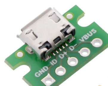
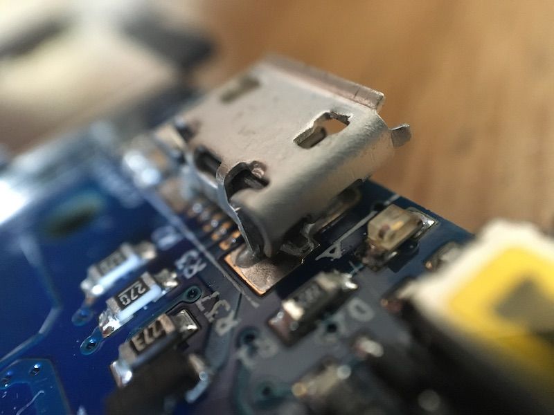
If someone near you has a hot air rework station, they can fix that port. Maybe.
I successfully fixed a micro usb, just like that one, on a Pi Touch Screen board a few days ago. Also had been torn off by the cable when moving the board.
Anyway, if you know someone, have them take a look.
-
@Tobs94 said in Broke Usb / Duet Wifi no connection:
there is a Jst port above the usb.
Will it be possible to solder there ?no, the jtag port does not have the usb signals.
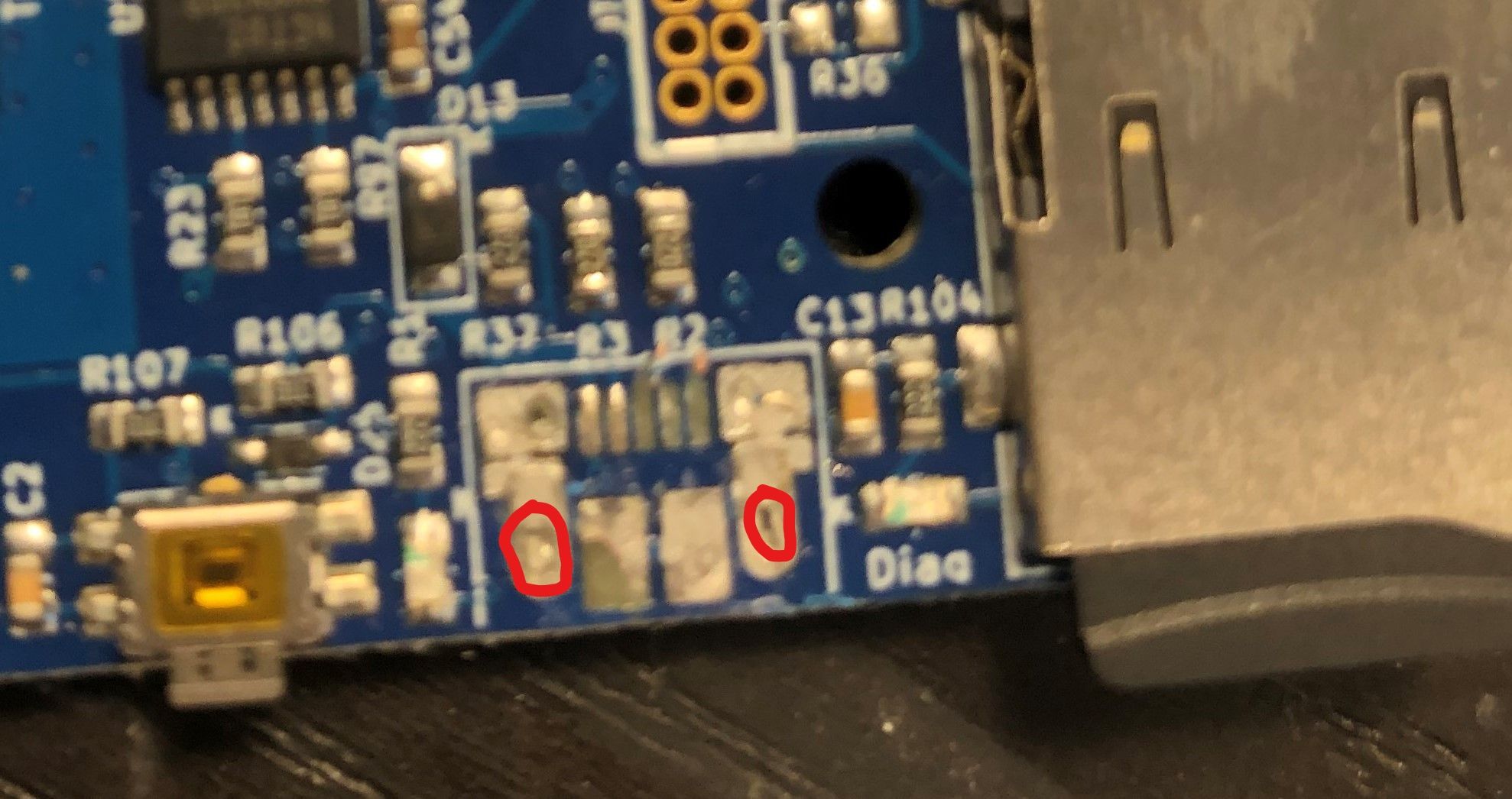
can you maybe show me a photo where i have to solder the wires. on the 5 little ares or where ?
"yes" normally on the 5 pads, but as some of the pads are missing so to recommend where to solder we would need a clear picture of the area.
(or using a usb to 3.3v ttl adapter like the ubiquitous ftdi cable and plug it to the PanelDue port)
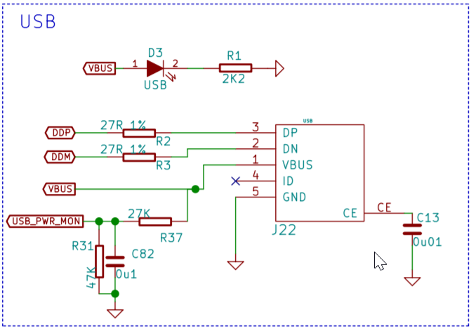
by the looks of it you could solder to the side closest to the usb connector on R3 and R2 just be quick about it so you don't detach the resistor (they have very little mass and can heat up the whole thing enough to come loose even if you just solder on one side). Then ground and 5v you can find "anywhere". looks like the 5v pad on the usb connector is okay, but ground and d+ is missing. (if the board has Vin you don't need 5v/Vbus) -
This post is deleted! -
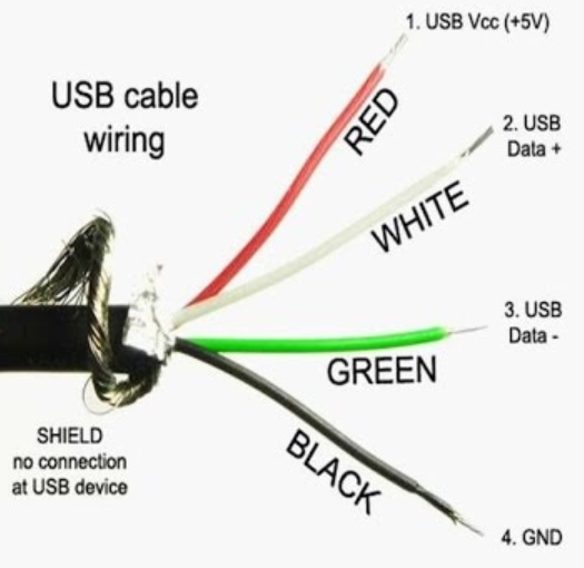
Yes I have powerd the board by 24v power supply. So I just have to solder the wires green and white too r2 and r3 ?
Should be right ?@bearer
-
you'll need a ground refrence as well but yeah.
white lead to
R2and green lead toR3
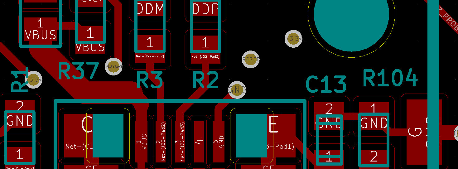
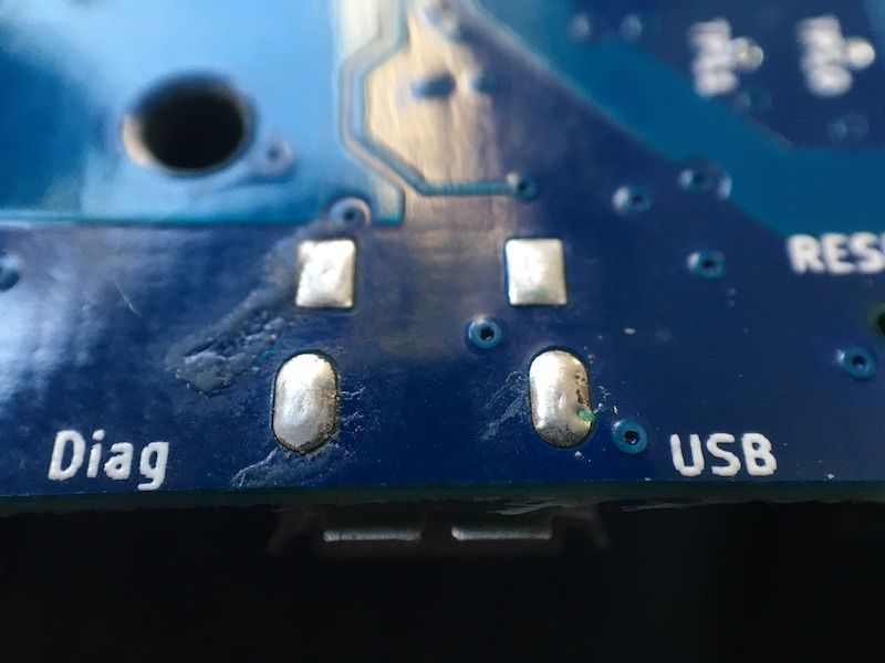
For future refrence, shows optional pads to solder Red/VBUS to and Black/GND.
-
If pin 1 is ripped up, this is an alternative ground.
Delta / Kossel printer fanatic
-
Or any other ground, on a fan or io or whatever.
-
@Danal said in Broke Usb / Duet Wifi no connection:
If pin 1 is ripped up, this is an alternative ground.
Those pads are not suitable, because they are connected to ground through a capacitor. A ground on an endstop connector would be suitable.
-
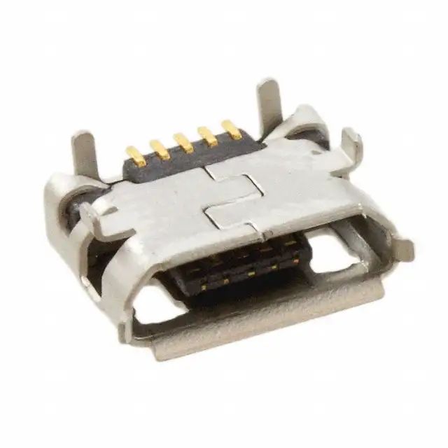
Good USB connectors are secured to the PCB with through-hole solder. This makes the mechanical connection much stronger. Otherwise they peel easily, often with pads.
-
@zapta said in Broke Usb / Duet Wifi no connection:
Good USB connectors are secured to the PCB with through-hole solder. This makes the mechanical connection much stronger. Otherwise they peel easily, often with pads.
Yes, just like the ones on the Duet 2 Wifi/Ethernet/Maestro and Duet 3!
Ian
Bed-slinger - Mini5+ WiFi/1LC | RRP Fisher v1 - D2 WiFi | Polargraph - D2 WiFi | TronXY X5S - 6HC/Roto | CNC router - 6HC | Tractus3D T1250 - D2 Eth
-
Is there a reason not to use the GND pads on the components surrounding the USB connector? The screenshot I posted show three GND pads next to the missing USB connector
(Pin 1 is 5v, and probably easier to solder to D1 than the remaining pads for the average tinkerer?)
-
Those nearby would all be fine.
-
fixed it with wiring on.
But now my Modul still not running without Usb.
https://forum.duet3d.com/topic/14247/wifi-module-not-starting-on-boot/6
-
Follow from step 6:
https://duet3d.dozuki.com/Guide/1.)+Getting+Connected+to+your+Duet/7
-
@droftarts said in Broke Usb / Duet Wifi no connection:
Yes, just like the ones on the Duet 2 Wifi/Ethernet/Maestro and Duet 3!
Very good. Not visible in the PCB screenshot above.
-
@zapta The lesson was learnt a long time ago with the Duet 0.6, where the USB port was surface mounted. I repaired a lot of them at RepRapPro, when possible. I think David redesigned the 0.85 with through hole. Don't know why the PCB picture isn't showing the via, but looks like the silkscreen or solder mask layers are covering it.
Just got a camera phone macro lens so thought I'd try it out:
Ian
Bed-slinger - Mini5+ WiFi/1LC | RRP Fisher v1 - D2 WiFi | Polargraph - D2 WiFi | TronXY X5S - 6HC/Roto | CNC router - 6HC | Tractus3D T1250 - D2 Eth
-
@droftarts said in Broke Usb / Duet Wifi no connection:
Don't know why the PCB picture isn't showing the via
Most of the layers were hidden to make it easier to see the relevant pads to solder the USB wires to. The shield pads were not a concern in that respect.
The full four layer board is quite busy it seems, and it could well be kicad placed the silkscreen on top or that the copper layer is simply a solid pad when shown without holes; but again the objective for the picture was just to show alternative locations to solder wires
(Edit, it does seem the pad are shown with rectangular cutouts, rendered with the same colour as the other round hole to the right of the usb connector. Thin yellow outline and filled with the same colour as the silkscreen)
-
@A Former User said in Broke Usb / Duet Wifi no connection:
Is #4 on the PCB not used? I'm asking because my micro USB broke when I moved the printer with the cable inserted. When desoldered the port I found out that I am missing the pad on number 4 completely.
If it so that it's not in use then I guess I'm lucky. Otherwise, where do 4 go?