Cambio elettronica
-
@Phaedrux ok allora le fasi sono corrette, un problema in meno

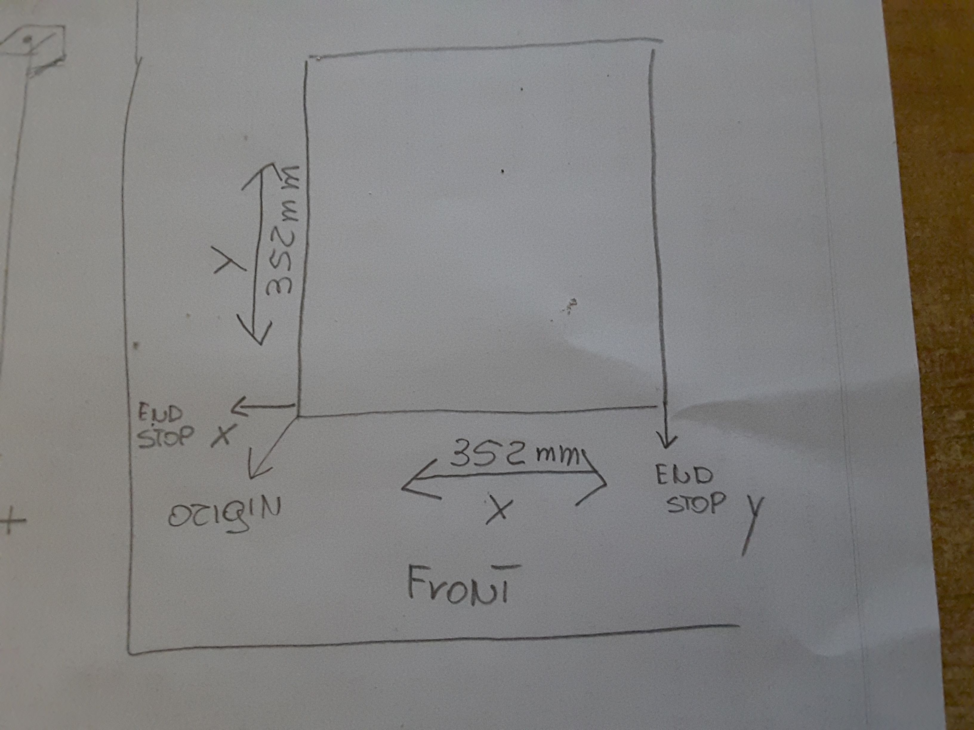
ho misurato gli assi e ho 352mm su x, e 352mm su y, si parla anche di valori negativi se la testina di stampa esce dal piatto
quindi nel comando M208 invece di X0 dovrei mettere M208 X-5 mm, perche' la testina e' fuori dal piatto di 5mm a sx come X min, e come X max dovrei mettere M208 X352 mm, perche' si parla di layout fisico giusto? -
That sounds correct.
-
-
; Configuration file for Duet WiFi (firmware version 3)
; executed by the firmware on start-up
;
; generated by RepRapFirmware Configuration Tool v2.1.8 on Thu Apr 02 2020 20:16:54 GMT+0200 (Ora legale dell’Europa centrale); General preferences
G90 ; send absolute coordinates...
M83 ; ...but relative extruder moves
M550 P"X5SA PRO" ; set printer nameM669 K1 ; select CoreXY mode
; Network
M552 S1 ; enable network
M586 P0 S1 ; enable HTTP
M586 P1 S0 ; disable FTP
M586 P2 S0 ; disable Telnet; Drives
M569 P0 S0 ; physical drive 0 goes backwards
M569 P1 S0 ; physical drive 1 goes backwards
M569 P2 S0 ; physical drive 2 goes forwards
M569 P3 S1 ; physical drive 3 goes forwards
M584 X0 Y1 Z2 E3 ; set drive mapping
M350 X16 Y16 Z16 E16 I1 ; configure microstepping with interpolation
M92 X80.00 Y80.00 Z800.00 E420.00 ; set steps per mm
M566 X900.00 Y900.00 Z12.00 E120.00 ; set maximum instantaneous speed changes (mm/min)
M203 X6000.00 Y6000.00 Z100.00 E1200.00 ; set maximum speeds (mm/min)
M201 X500.00 Y500.00 Z20.00 E250.00 ; set accelerations (mm/s^2)
M906 X800 Y800 Z800 E800 I30 ; set motor currents (mA) and motor idle factor in per cent
M84 S30 ; Set idle timeout; Axis Limits
M208 X-5 Y0 Z0 S1 ; set axis minima
M208 X352 Y330 Z400 S0 ; set axis maxima; Endstops
M574 X2 S1 P"! xstop" ; configure active-high endstop for low end on X via pin xstop
M574 Y2 S1 P"! ystop" ; configure active-high endstop for low end on Y via pin ystop
M574 Z1 S2 ; configure Z-probe endstop for low end on Z; Z-Probe
M558 P5 C"! zprobe.in" H5 F120 T6000 ; set Z probe type to unmodulated and the dive height + speeds
G31 P500 X0 Y0 Z2.5 ; set Z probe trigger value, offset and trigger height
M557 X60:300 Y50:300 S20 ; define mesh grid; Heaters
M308 S0 P"bedtemp" Y"thermistor" T100000 B4092 ; configure sensor 0 as thermistor on pin bedtemp
M950 H0 C"bedheat" T0 ; create bed heater output on bedheat and map it to sensor 0
M143 H0 S120 ; set temperature limit for heater 0 to 120C
M307 H0 B0 S1.00 ; disable bang-bang mode for the bed heater and set PWM limit
M140 H0 ; map heated bed to heater 0
M308 S1 P"e0temp" Y"thermistor" T100000 B4092 ; configure sensor 1 as thermistor on pin e0temp
M950 H1 C"e0heat" T1 ; create nozzle heater output on e0heat and map it to sensor 1
M143 H1 S280 ; set temperature limit for heater 1 to 280C
M307 H1 B0 S1.00 ; disable bang-bang mode for heater and set PWM limit; Fans
M950 F0 C"fan0" Q500 ; create fan 0 on pin fan0 and set its frequency
M106 P0 S0 H-1 ; set fan 0 value. Thermostatic control is turned off
M950 F1 C"fan1" Q500 ; create fan 1 on pin fan1 and set its frequency
M106 P1 S1 H1 T45 ; set fan 1 value. Thermostatic control is turned on; Tools
M563 P0 D0 H1 F0 ; define tool 0
G10 P0 X0 Y0 Z0 ; set tool 0 axis offsets
G10 P0 R0 S0 ; set initial tool 0 active and standby temperatures to 0C; Custom settings are not defined
-

-
asse X e Y tornano verso il finecorsa, fin qui tutto ok, ma il risultato non e' quello che mi aspettavo. "Foto in alto della dashboard"
-
@Leblond said in Cambio elettronica:
M574 X2 S1 P "! Xstop"; configure active-high endstop for low end on X via pin xstop
M574 Y2 S1 P "! ystop"; configure active-high endstop for low end on Y via pin ystopX2 and Y2 mean the endstops are at the high end of travel. So when homed the axis position would be the max value.
Is the X endstop on the right side? Is the Y endstop at the back?
-
no la stampante vista da "davanti", X si ferma a sx dove posizionato il finecorsa, Y si ferma davanti dove posizionato il finecorsa
-
ti mando schizzo
-

-
@Leblond said in Cambio elettronica:
no the printer seen from "front", X stops on the left where the limit switch is positioned, Y stops in front where the limit switch is positioned
Ok, go back to my post above: https://forum.duet3d.com/post/142912
You've managed to change the configuration to force it to work, but it's not working properly.
If the endstops are on the low end it must be M574 X1 Y1.
This also means the homing moves must be negative.
If the motors do not move the right direction at this point you must do these tests to correct the motor rotation:
https://duet3d.dozuki.com/Wiki/ConfiguringRepRapFirmwareCoreXYPrinter#Section_Testing_motor_movement
-
ok guardo
-
quindi quando si parla di parte bassa si intende il davanti della stampante e parte alta il dietro, giusto?
ho riportato i valori su S1 ma si spostano di pochi cm. e mi da errore, quindi presumo che bisogna far girare i motori al contrario? -
; Configuration file for Duet WiFi (firmware version 3)
; executed by the firmware on start-up
;
; generated by RepRapFirmware Configuration Tool v2.1.8 on Thu Apr 02 2020 20:16:54 GMT+0200 (Ora legale dell’Europa centrale); General preferences
G90 ; send absolute coordinates...
M83 ; ...but relative extruder moves
M550 P"X5SA PRO" ; set printer nameM669 K1 ; select CoreXY mode
; Network
M552 S1 ; enable network
M586 P0 S1 ; enable HTTP
M586 P1 S0 ; disable FTP
M586 P2 S0 ; disable Telnet; Drives
M569 P0 S1 ; physical drive 0 goes backwards
M569 P1 S1 ; physical drive 1 goes backwards
M569 P2 S0 ; physical drive 2 goes forwards
M569 P3 S1 ; physical drive 3 goes forwards
M584 X0 Y1 Z2 E3 ; set drive mapping
M350 X16 Y16 Z16 E16 I1 ; configure microstepping with interpolation
M92 X80.00 Y80.00 Z800.00 E420.00 ; set steps per mm
M566 X900.00 Y900.00 Z12.00 E120.00 ; set maximum instantaneous speed changes (mm/min)
M203 X6000.00 Y6000.00 Z100.00 E1200.00 ; set maximum speeds (mm/min)
M201 X500.00 Y500.00 Z20.00 E250.00 ; set accelerations (mm/s^2)
M906 X800 Y800 Z800 E800 I30 ; set motor currents (mA) and motor idle factor in per cent
M84 S30 ; Set idle timeout; Axis Limits
M208 X-5 Y0 Z0 S1 ; set axis minima
M208 X352 Y330 Z400 S0 ; set axis maxima; Endstops
M574 X1 S1 P"! xstop" ; configure active-high endstop for low end on X via pin xstop
M574 Y1 S1 P"! ystop" ; configure active-high endstop for low end on Y via pin ystop
M574 Z1 S2 ; configure Z-probe endstop for low end on Z; Z-Probe
M558 P5 C"! zprobe.in" H5 F120 T6000 ; set Z probe type to unmodulated and the dive height + speeds
G31 P500 X0 Y0 Z2.5 ; set Z probe trigger value, offset and trigger height
M557 X60:300 Y50:300 S20 ; define mesh grid; Heaters
M308 S0 P"bedtemp" Y"thermistor" T100000 B4092 ; configure sensor 0 as thermistor on pin bedtemp
M950 H0 C"bedheat" T0 ; create bed heater output on bedheat and map it to sensor 0
M143 H0 S120 ; set temperature limit for heater 0 to 120C
M307 H0 B0 S1.00 ; disable bang-bang mode for the bed heater and set PWM limit
M140 H0 ; map heated bed to heater 0
M308 S1 P"e0temp" Y"thermistor" T100000 B4092 ; configure sensor 1 as thermistor on pin e0temp
M950 H1 C"e0heat" T1 ; create nozzle heater output on e0heat and map it to sensor 1
M143 H1 S280 ; set temperature limit for heater 1 to 280C
M307 H1 B0 S1.00 ; disable bang-bang mode for heater and set PWM limit; Fans
M950 F0 C"fan0" Q500 ; create fan 0 on pin fan0 and set its frequency
M106 P0 S0 H-1 ; set fan 0 value. Thermostatic control is turned off
M950 F1 C"fan1" Q500 ; create fan 1 on pin fan1 and set its frequency
M106 P1 S1 H1 T45 ; set fan 1 value. Thermostatic control is turned on; Tools
M563 P0 D0 H1 F0 ; define tool 0
G10 P0 X0 Y0 Z0 ; set tool 0 axis offsets
G10 P0 R0 S0 ; set initial tool 0 active and standby temperatures to 0C; Custom settings are not defined
-
non funziona
-
siamo ritornati al punto di partenza quando non andava
-
@Leblond said in Cambio elettronica:
Correct.
@Leblond said in Cambio elettronica:
when we talk about the lower part we mean the front of the printer and the upper part the back, right?
Correct.
@Leblond said in Cambio elettronica:
; Axis Limits
M208 X-5 Y0 Z0 S1; minimum axis set
M208 X352 Y330 Z400 S0; set axis maxima
; Endstops
M574 X1 S1 P "! Xstop"; configure active-high endstop for low end on X via pin xstop
M574 Y1 S1 P "! ystop"; configure active-high endstop for low end on Y via pin ystop
M574 Z1 S2; configure Z-probe endstop for low end on ZCorrect.
@Leblond said in Cambio elettronica:
; homeall.g
; called to home all axes
;
; generated by RepRapFirmware Configuration Tool v2.1.8 on Thu Apr 02 2020 16:46:31 GMT + 0200 (Central European
Summer Time) G91; relative positioning
G1 H2 Z5 F6000; lift Z relative to current position
G1 H1 X-335 Y-335 F1800; move quickly to X or Y endstop and stop there (first pass)
G1 H1 X-335; home X axis
G1 H1 Y-335; home Y axis
G1 X5 Y5 F6000; go back a few mm
G1 H1 X-335 F360; move slowly to X axis endstop once more (second pass)
G1 H1 Y-335; then move slowly to Y axis endstop
G90; absolute positioning
G1 X60 Y50 F6000; go to first bed probe point and home Z
G30; home Z by probing the bedCorrect.
Now you must do these tests to find the correct motor settings.
@Leblond said in Cambio elettronica:
M569 P0 S1; physical drive 0 goes backwards
M569 P1 S1; physical drive 1 goes backwardsChange these to S0.
Then move print head to the center and send G92 X100 Y100.
Then send G91 G1 S2 X10 F3000
If the head moves diagonally in the +X and +Y directions, all is well. If it moves in the -X and -Y directions, change the S parameter to S1 in the M569 P0 command. If it moves towards +X and -Y, or towards -X and +Y, then either turn the power off and swap the X and Y motor connections, or use M584 in config.g to swap the X and Y motor drivers over.
When you have the X motor moving correctly, test the Y motor by sending from the console: G91 G1 S2 Y10 F3000
If the head moves diagonally in the +X and -Y directions, all is well. If it moves in the -X and +Y directions, change the S parameter in the M569 P1 command to S1.
-
m569 p0 s0 e m569 p1 s0 cambiati
-
@Phaedrux said in Cambio elettronica:
G92 X100 Y100 ;questo dice alla stampante che si trova a x100 e y100 giusto?
G91 G1 H2 X10 F3000 : si e' spostata in diagonale verso dx e rear -
@Leblond said in Cambio elettronica:
@Phaedrux said in Cambio elettronica:
G92 X100 Y100 ;questo dice alla stampante che si trova a x100 e y100 giusto?
Correct
G91 G1 H2 X10 F3000 : si e' spostata in diagonale verso dx e rear
Correct.
Now move on to the next move G91 G1 S2 Y10 F3000