Mixed voltage for 24V fans on toolboard.
-
Hello,
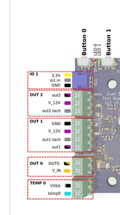
I am wiring up 2 toolboards, I would like to control the fans on my hotends. The fans are 24V and the toolboard fan out puts are 12V. I would like to wire +24v directly to the fans and switch the negative side using OUT 1on each board. Bassed on the pinout would I connect the negative to out1, which is pwm 12v? toolboard.JPG
-
A couple of people have done this, and it seems to work. I have not personally done it.
The one with the black/purple square is the one that switches ground.
-
Did you try this, and does it work?
Is this safe to do in regards to blowing anything @dc42 ?
While on topic, is it possible to somehow convert the 12v heater out to 24v without external mosfet board?RepRapFirmware supported G-codes: https://duet3d.com/wiki/G-code
-
@dintid said in Mixed voltage for 24V fans on toolboard.:
Is this safe to do in regards to blowing anything
No. you can only safely use lower voltages than what the Vfan for the mosfet is even with low side switching.
ref comment from dc42 in this thread https://forum.duet3d.com/post/160986
-
Sad to hear that, but awesome to get it clarified. Thanks mate
")
RepRapFirmware supported G-codes: https://duet3d.com/wiki/G-code
-
@dintid if you reall want to use 24v you could remove the diode (or cut the trace) that causes the problem and just make sure to not have any inducitive loads on the output.
(edit: see dc42 reply further down)
(if I were to modify it I would desolder the diode, put some PET/PEI tape over the cathode pad to insulate it, solder the anode back on the board and solder a jumper wire from the cathode to Vin/24v. that should make it work without having to resort to external mosfets or external dc/dc converters, but I've got a sneaking suspiscion the warranty would be out the window..)
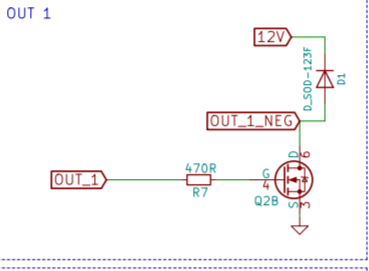
edit: forgot the schematic showing D1 (or D2 for out2)
-
@bearer I'm not at all component savvy, so that's a no go for me.
If you replace "diode", "inductive loads" and "cathode" with "blah blah blah" you'd get an idea of what I just understood from what you just said
Thanks though for the suggestion.RepRapFirmware supported G-codes: https://duet3d.com/wiki/G-code
-
@dintid fair enough, I was open to that possibility - but also figure the information is here for the next guy as well.
Diode is (usually) a small black chip with 2 terminals. Electronic check valve essentially. They're just behind the screw terminals and labeled D1 and D2 on the PCB.
Inductive loads is in simpler terms "anything" that isn't a heater, brushless fan or LED. A pump or brushed fan being the prime example of what not to connect if the diode is simply removed; making the modification means this is not a concern.
Cathode is the one of the two terminals on the Diode and is usually marked with a line on the body, and Duet people have also put a K on the PCB to show which way to mount it. (The other terminal is the Anode ref wikipedia)
As only the schematic has been released so far (there is another thread for those who want to discuss that) and not he KiCad sources or gerber files I can't easily make a diagram, but from the picture it looks like simply cutting a trace will not suffice, soldering is needed, Custom wiring to get Vin to the fan, simplest looks to be to wire it along with the heater to Vin on Out0.
-
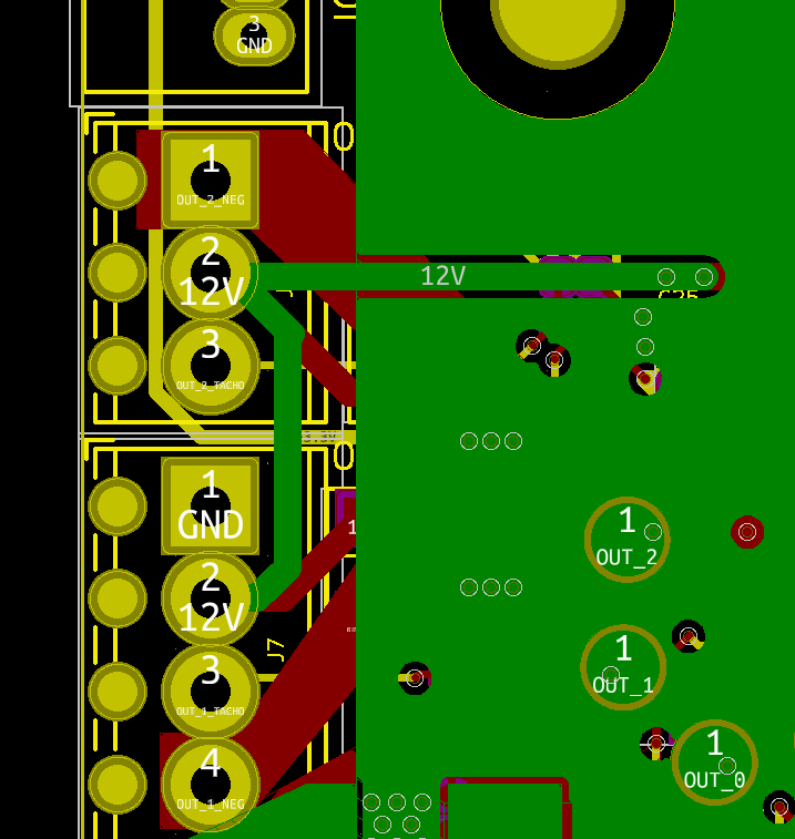
Here's the PCB for that part of the board (this is for the v1.0 board, but the v0.6 board is similar):
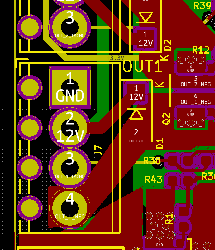
It looks to me that you can cut the trace on back copper (green in this image) that feeds 12V to the 12V pin on OUT1, and jumper that pin to VIN instead. The diode is rated at 40V so it will be OK with 24V. The mosfet is rated at 60V.
PS - that +12V trace comes via OUT2, so if you want to convert both outputs to VIN, cut the back copper trace that feeds 12V to the centre pin of OUT2 instead.
Duet WiFi hardware designer and firmware engineer
Please do not ask me for Duet support via PM or email, use the forum
http://www.escher3d.com, https://miscsolutions.wordpress.com -
@dc42 if the pcb is multilayered id be afraid to cut too deeply.
Maybe a physical jumper solution could be implemented in future versions.
Main concern for me is the BLTouch not working for me. Hopefully I’ll have time to test it on main board tomorrow.RepRapFirmware supported G-codes: https://duet3d.com/wiki/G-code
-
@dintid said in Mixed voltage for 24V fans on toolboard.:
if the pcb is multilayered id be afraid to cut too deeply.
it is, but not a problem to cut just the bottom layer - in adittion there is plenty of space to cut the trace where there aren't any mid layer signals.
if you were to try it, which output would you use with 24v? out1, out 2 or both?
-
@bearer I’m not going to cut anything, as it would introduce a new variable on my board, but if I were, I’d cut both.
-
@dc42 hypothetically if you are not using the 12v for anything, what damage would be caused by feeding Vin to the 12v through the fly back diode?
-
@baird1fa said in Mixed voltage for 24V fans on toolboard.:
@dc42 hypothetically if you are not using the 12v for anything, what damage would be caused by feeding Vin to the 12v through the fly back diode?
That's a good point! The 5V regulator is fed from +12V, however there is a protection diode between the external 12V output and the internal one. So it should be safe to connect the external 12V output to VIN. There is a 1uF capacitor C26 connected to the external 12V rail which we have specified as 16V, however the capacitor we actually use is rated at 50V. I've made a note to increase it to 50V officially.
Duet WiFi hardware designer and firmware engineer
Please do not ask me for Duet support via PM or email, use the forum
http://www.escher3d.com, https://miscsolutions.wordpress.com -
@dc42 I’m not sure I follow all of that. So if 24V was applied to Vin and Vin was used to power a fan as the + terminal and the - was connected to the out1 PWM terminal. You would feed 24V into the 12V supply through the fly back diode. But this would only affect out1 and out2 and not the 5V supply because there is protection internally to the 5V supply?
So in conclusion it would only harm the 12V output terminals if anything at all?
-
@baird1fa said in Mixed voltage for 24V fans on toolboard.:
@dc42 I’m not sure I follow all of that. So if 24V was applied to Vin and Vin was used to power a fan as the + terminal and the - was connected to the out1 PWM terminal. You would feed 24V into the 12V supply through the fly back diode. But this would only affect out1 and out2 and not the 5V supply because there is protection internally to the 5V supply?
So in conclusion it would only harm the 12V output terminals if anything at all?
Correct. You could even connect +12V at the OUT1 or OUT2 connector to VIN. Note, I haven't tested this yet, I'll try to do this tomorrow.
Duet WiFi hardware designer and firmware engineer
Please do not ask me for Duet support via PM or email, use the forum
http://www.escher3d.com, https://miscsolutions.wordpress.com -
@dc42 Did you test this David? Is it safe to do? x
-
@dc42 Have you ever tested this? it would be nice to know if this works without problems or is it just better to disconnect the 12v trace.
-
@olliss it's safe to do. The next revision of the tool board will have a jumper to do exactly this.