Hello all, I just wanted to let any who is interested know that Autodesk has updated their post processor, available to download on their site, to include the G2/G3 commands.
Best posts made by baird1fa
-
RepRap post on autodesk siteposted in CNC
-
RE: Help with heated bed configposted in Duet Hardware and wiring
Not related to 3D printers but I regularly heat large metal tubes at work and use many heaters. Up to 40 on a system and each one controlled independently. Each heater does have an effect on the others but usually it is minimal.
It might be a good idea to do that but it may also complicate the slicing setup.
I’m not sure if that was helpful or not.
-
RE: Automatically setting M558 Z valueposted in General Discussion
@Phaedrux well I was able to get the bed cleared off and run my G32 (bed.g) which I added a link to my macro and after the macro I added the M500 P31 in the bed.g and that saved the offsets correctly. So that gets me a work around.
-
RE: Help with heated bed configposted in Duet Hardware and wiring
Luckily you are using thermocouples. If you wire them all together the actual voltage signal will average out. So if you just take all the +ve leads and connect together on the same +ve terminal and take the -ve leads to the same -terminal it will average out the three sensor readings. Its a pretty old school trick.
good luck.
-
RE: External driver wiring to Duet 2 breakout boardposted in Duet Hardware and wiring
I think I just replied to your other post. But you can use the outputs, basically they are a switch so just ware an input and a ground to the alarm terminals on the driver. Then you need to setup a trigger (M581) for those inputs along with the action to take. You can run a macro or a pause or an estop.
-
RE: PWM to 10V via e0heater always gives 10Vposted in CNC
@educatingsavvas
I just wired up one of these and it works too.One thing to note is that using less than 3000hz seems to result in the generation of a 0-10v signal that the VFD sees as oscillating and then it changes frequencies a lot. It ramps up and down 10’s of hertz.
-
RE: BLTOUCH probingposted in General Discussion
It will likely be in this part of your config.g file.
G31 P25 X-31 Y0 Z0.6                               ; set Z probe trigger value, offset and trigger height
M557 X20:215 Y20:215 S64                           ; define mesh grid
Likely the X-31 is no longer accurate. With the probably area being X20-215 and a -31 offset it could still probe 11mm off the bed (I think). But those are the parameters that you need to adjust to get the probe back on the bed.
-
RE: Vary Frequency in PWM output instead of duty cycle.posted in Firmware wishlist
what you are looking for is not PWM (pulse width modulation) you want FM (Frequency Modulation). I would suspect that the duet is not setup to use FM as it is not mentioned anywhere in the documentation. As Bearer said you can change the base frequency of the PWM and if you set the PWM to 50% and then changed the base frequency it might work to act like frequency modulation, but i doubt it. Give it a try, it can't hurt.
I do believe you can buy conversion hardware that will take a PWM signal and convert it to an FM signal.
-
RE: Duet 3 rrf 3 BLTouchposted in Duet Hardware and wiring
@Phaedrux maybe he has the same issue I had and it is interference with his stepper motors. It possible it was working for testing then he tried to print and now it doesn’t work? We can only guess.
@mrenz999 Try sending an M18 E0 command before you attempt to use the probe.
-
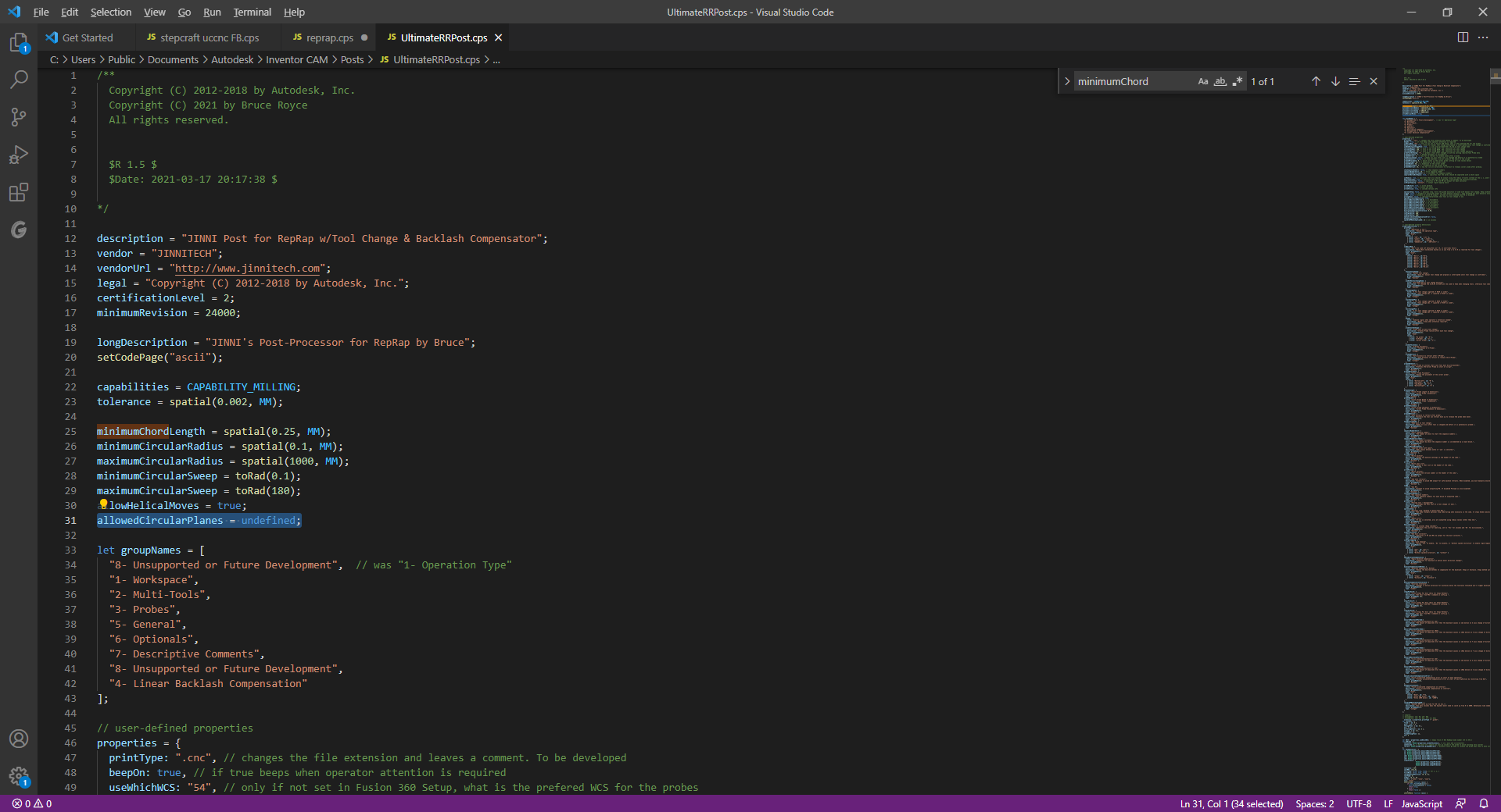
RE: The ULTIMATE RepRap Post-Processor for Fusion 360posted in CNC
I have managed to fix the G2-G3 issue with this post (or at least is was an issue for me)
there is a piece missing after allowedHelicalMove = true; which should be allowedCircularPlanes = undefined;
Then under // circular output all the i, j, and k variables are forced false that needs to be replaced with
// circular output
false
falsevar iOutput = createReferenceVariable({ prefix: "I"}, xyzFormat);
false
falsevar jOutput = createReferenceVariable({ prefix: "J"}, xyzFormat);
false
falsevar kOutput = createReferenceVariable({ prefix: "K"}, xyzFormat);
false
false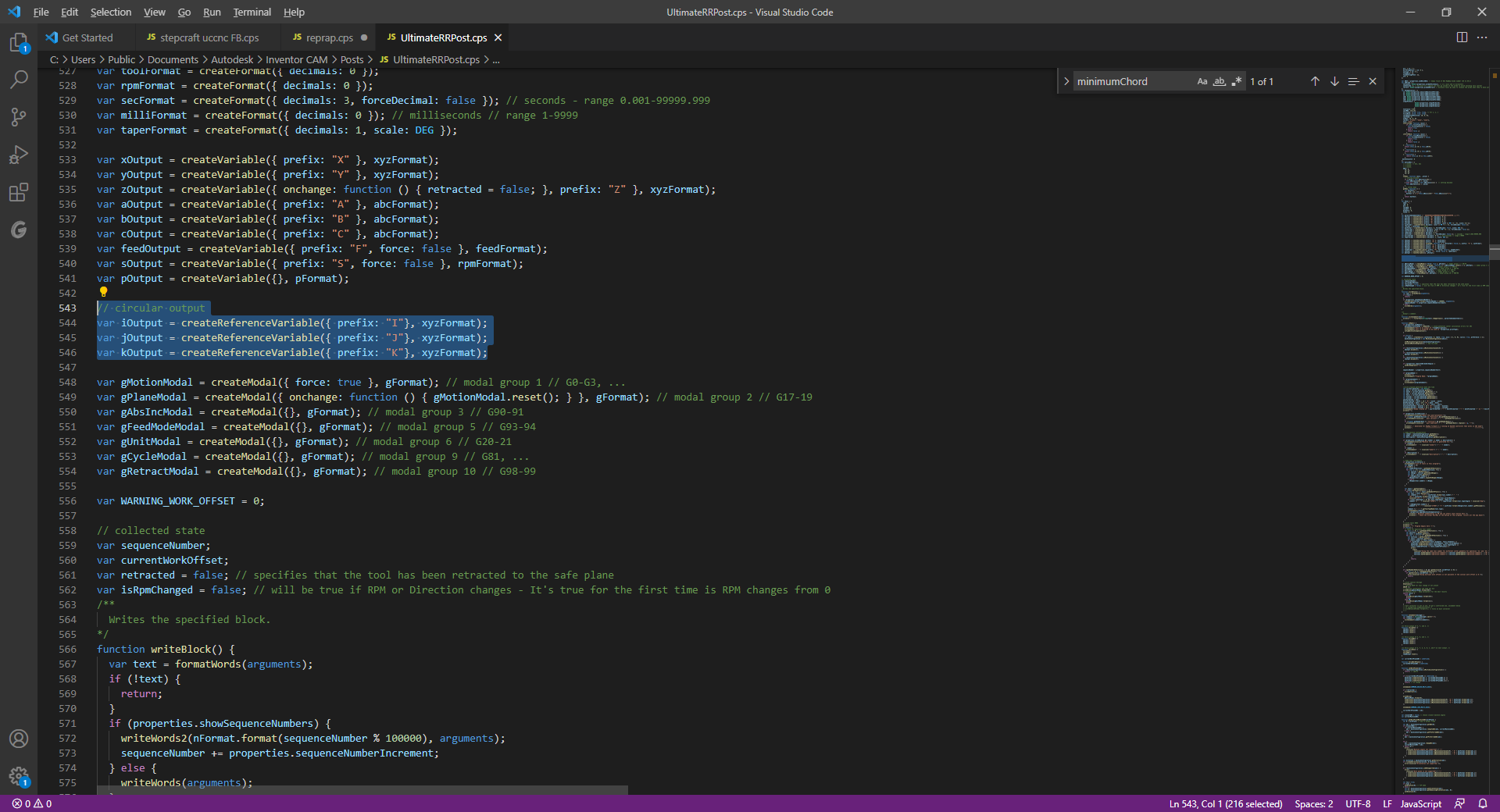
and that should give you G2 and G3 movements. I haven't tested the Gcode yet but at least circular movements are arcs and not thousands of segments.
Latest posts made by baird1fa
-
Acceleration algorithm for step pulse generatorposted in Off Topic
Hello all. I’m working on a step controller using an FPGA to generate the pulses. The issue I’m having is calculating acceleration. The software I’m using makes it easy to use clock cycles of the 40MHz for the timing of the pulse and the frequency of the pulses. I can generate consistent pulses. Where I am struggling is to make controlled movement where the acceleration is consistent over a given number of pulses then stay constant, followed by a controlled deceleration.
If I need say 100 pulses to accelerate over say 0.5 seconds then that would be 2million clock cycles for acceleration. If I shorten the timing between pulses I don’t get smooth acceleration but rather slow acceleration with a sudden quick ramp at the end.
I can’t seem to find anything on google so I thought I would reach out here as I can only assume someone on here has solved this before.
Thanks.
-
Stepper pulsesposted in General Discussion
Hello everyone. I’m wondering if any of you know what the wave form looks like for pulses being sent to steppers from the duet. Are the pulses just a fixed width (time) and there is a variable space between them. Or is it a 50% duty cycle and the frequency just varies?
Thank you.
-
RE: floor meta command not working on CNC state of boardposted in CNC
Well I just figured it out, it is because in the CNC mode, the () brackets need to be encased with {} brackets. and that isn't needed in the 3D printer mode.
-
floor meta command not working on CNC state of boardposted in CNC
Hello,
I'm running a duet 2 wifi on a CNC router as well as a 3D printer. I was using the 3D printer to practice some meta commands for an attempt to make a spoil board facing program. I was able to get the program to work the way I want it on my 3D printer and one of the functions I'm using is the "floor" command to do some division for me where I just want the integer value. The floor command is not working when I try it on my CNC router. I'm running the same version of reprap on both units. 3.5.0 rc1. Does anyone else have this same issue?
-
When would you use M110?posted in General Discussion
Hello, I'm just looking through the GCode directory and I'm curious when you would use the M110 command. Can anyone provide an example of when to use that?
Thanks.
-
RE: Duet 3 Touch Probe Digitizerposted in General Discussion
I realize this is an old thread but I'm curious if any head way has been made. I was thinking of trying to do something like this with the available touch probes. I have installed this probe on my machine and written a macro to find the XY coordinate of the corner of the work piece shown here: https://youtu.be/sxFnuANYMj0?si=RC7X4tuDhhlL49RF
With the Meta commands is it possible to make reprap generate an output file using the M28 command an the M114 command to store the point cloud data. I think all that would be needed is a set of commands like move so many mm in x then do a probe, on contact save that coordinate, lift up a bit, make another move and probe. Repeat that until there is some user defined stopping point, then move in the Y direction and move back to the X starting position and repeat for as many Y directions as needed.
Is this something that anyone has done, or is there an example of this with meta commmands. I'm very new to meta command and text based programming in general.
-
RE: Macro errorposted in CNC
I found my issue, I was using a M21 where I should have had G21 to put the macro into mm.
-
Macro errorposted in CNC
Hello everyone, I've installed a 3D touch probe on my duet run CNC machine and I'm having an issue with the macro that I'm trying to use for probing the X and Y of the workpiece.
Here is the macro that I'm using and when I call it it runs fine, but I get an error that says:
M98 P"0:/macros/Touch Probe/3D Probe corner"
Error: SD card has open file(s);This will probe the bottom Left corner of the work piece ;First Probe the Z height M21 ;This macro uses mm moves M98 P"/macros/Touch Probe/z probe.g" ;Run Z probe to find surface of material G91 ;Set relative moves G0 X-25 ;Move 25mm away from current position G0 Z-8 ;Move down 8mm, 3mm below surface of work piece G90 ;Set Absolute moves M98 P"/macros/Touch Probe/X Probe.g" ;Run X probe macro G91 ;Set Relative moves G0 Z10 ;Lift probe to clear work piece G0 X20 Y-45 ;Move Probe to position for Y probe G0 z-10 ;Move Probe into Z position for Y probe G90 ;Set Absolute moves M98 P"/macros/Touch Probe/Y Probe.g" ;Run Y probe macro G91 ;Relative move G0 Z10 ;Lift probe to clear material G90 ;Absolute move G1 X0 Y0 F500 ;Move to new soft homeI don't see any thing about this error in my google search or a search of the duet documentation site.
There are no errors is I run the files individually, only if I run the main macro.
-
RE: extracting the machine unit from object modelposted in CNC
@baird1fa I think I found the solution. It looks like the G20 and G21 are only changed temporarily when called inside of a macro and revert back once the macro is completed.
-
extracting the machine unit from object modelposted in CNC
Hello everyone,
I'm looking for some help to extract the machine unit, set by G20 and G21, from the object model to use in macros.
Essentially I want to be able to run my machine in either mm or inches. The issue I have is when my Gcode sets the machine to inches all the macros and such don't work as they were written expecting the machine to be in inches.
I'd like to add a small script at the beginning of any macro that checks if the machine is in machine is in inches and if it is sets it G21 (mm) before proceeding and then sets it back to G20 if needed to continue running the job.
I want to do this because I have macros that will run during a job and they need to be in known unit.
I have found an object model (inputs[].distanceUnit) but I'm not sure how to utilize it.
Thank you.