Precision Piezo z probes guide for duet users reference
-
DWC - Duet control web pages & sorry I should have taken in what you've written...
So I take it, that at the fourth point the probe hits the bed ??
FYI, as it looks like you are still on RRF2, if so, this was my setting for that version (which worked well)
M558 P8 I1 R0.5 H5 T24000 F250 A3 S0.08 ; Set Peizo - P probe type, I Invert, R recovery time, H dive hight, T inter-probe-point speeds, F Probing Speed, 3 Dives , S calculated difference
-
I've try your code but for me dosenìt work.. the bed don't feel the probe..
-
Hey all!
So I have been playing with the piezo probes a couple of times now. However, even after having had my hands on 4 sets of piezo probes, it just does not work.
My setup is a Duet Wifi with under-the-bed piezo sensors. They are Andromeda sensors hanging under the bed, screwed to the frame, with the central Screw propping up the bed.
The relevant Duet Code I am using is as follows:
M558 H25 T9000 A10 P3 I1 R0.4 S0.02 F500
G31 X0 Y0 Z-0.15 P100
In order to test I run following script:
G28 X

G1 Z25 F8000
G30 S-1
...the above two lines  *100

G28 X
I get a drift or roughly 0,3mm over the first 30 measurements, with increments of drift ranging from 0 to 0,018mm. After leveling out at approximately the 30-probe mark (this is by no means a hard limit) measurements jump back and forth between 0,002mm to max 0,015mm altough the larger differences are usually followed by an equally large countermovement (so if it measures 0,015 higher than the previous measurement, it is likely it is going to measure 0,015 lower the next cycle around).
I don't know what it is but with this problem I can not work with the piezo probes especially not with the arrangement I have got here.
I tried a lot and t kills me that it does not work. On top, I actually thought it was the perfect system for our business 3D printer and it not working doe not really help me at all.
I posted a similar request in the reprap forum, as I am trying to cover all my bases here and the problem persists for more than 12 months already.
Best regards
Deltasquare -
@Deltasquare said in Precision Piezo z probes guide for duet users reference:
M558 H25 T9000 A10 P3 I1 R0.4 S0.02 F500
I think this could be improved for accuracy/repeatability:
P3 - This mode is the analogue input. Usually piezos use the P8 (digital, unfiltered, faster) mode. You will probably still need to invert, which you're doing already.
H25 - this is the dive height. Unless your bed is wildly out of whack, you don't need to move the probe up this high. Try H5. Will also speed things up.
F500 - this is the probing speed. 500mm/min is FAST for probing. Most people in this thread seem to use F120. Try slow, then speed up if it still holds accuracy.Ian
-
Hi Ian!
Thank you for your quick reply!
ad dive height.:
I have run apprx 20 tests with 100 reps each for distinguishing the optimal probing height. I previously got the least offset when probing from 25mm height. My guess is that at 25mm is a multiplier of the full steps required to get to the bed.ad analog vs digital.:
I had the impression that the analog was supposed to be the more accurate, is this not true?I am implementing all your suggestions as I am writing. I will be getting back with results.
thk
dsq -
So I implemented the changes as suggested. There is no change.
In this attempt I have run 3 scripts twice each. The results are supporting one another in most cases.
Run1 & 2 were with the previous test script.
Run 3 & 5 were with the suggested improvements:
Improvements:
M558 H5 T9000 A10 P8 I1 R0.4 S0.02 F120	; M558 dive Height, Travel speed, probing Attempts, Probe type, Remain, dive speed F
G31 X0 Y0 Z-0.15 P100				; Set Z probe trigger value, offset and trigger height Z-0.012 / Z-0.45
Script Z5:
G28 X

G1 Z5 F3000
G30 S-1
... above two lines x100

G28 X
and out of curiosity i also run the same settings with following script, to move the sliders a little more, as it is likely to happen in my setup.
Script Z5 updown:
G28 X
G1 Z5 F3000

G30 S-1
G1 Z40 F6000
G1 Z5 F6000
... above three lines x100
G28 X
Results you can find here, mind the tabs:
https://drive.google.com/file/d/19arr1t3R8NCq5BxTw2s26OPm-Wabvvv0/view?usp=sharing -
@droftarts said in Precision Piezo z probes guide for duet users reference:
@Deltasquare said in Precision Piezo z probes guide for duet users reference:
M558 H25 T9000 A10 P3 I1 R0.4 S0.02 F500
I think this could be improved for accuracy/repeatability:
P3 - This mode is the analogue input. Usually piezos use the P8 (digital, unfiltered, faster) mode. You will probably still need to invert, which you're doing already.
H25 - this is the dive height. Unless your bed is wildly out of whack, you don't need to move the probe up this high. Try H5. Will also speed things up.
F500 - this is the probing speed. 500mm/min is FAST for probing. Most people in this thread seem to use F120. Try slow, then speed up if it still holds accuracy.Ian
The "P" mode for the Orion depends on which headers on the Orion you're connected to. The newer boards have both analog and digital outputs so P1 (or P3) is correct for the analog output and P8 is correct for the digital output. P3 is like P1 except it doesn't drive the Duet's output pin low which the Orion doesn't need anyway.
The unfortunate situation is that the "proper" configuration depends on which Orion you have, which Orion outputs you want to use, which Duet you have, which Duet connector the Orion is connected to, and which version of RRF you run.
The Duet connector is important because only some of the IO connectors on the Duet3 support analog input.
-
Hi gtj0!
Thank you for your input! I thought there has been a change as I was confused last time I saw a digital and an anlog input on the universal Piezo Z-Probe PCB!
Unfortunately I have not got my hands on an Orion sensor, as we are only using Andromeda sensors which only have two leads coming out compared to the 6 from the Orion. What do you suggest for the Andromeda? Would you have it plugged into Analog or Digital? (On this topic: Is the Orion the better solution of the two? I could also mount 3 Orions under the bed)
However here the Versions:
- PP-PCB v2.85
- DuetWiFi v1.04c
- Andromeda v1.0
Connection PCB <-> Duet is via the "Probe" plug.
![Picture of duet Board with version number and duet "Probe" Plug attached to the z-probe]
https://drive.google.com/file/d/1VvkJIHuc_7ZN2v5XB3PSSQCO7H-Kn-x8/view?usp=sharingFirmware Version: 2.05 (2019-12-13b1)
WiFi Server Version: 1.23
Web Interface Version: 1.22.6 -
@Deltasquare you cannot connect andromeda directly to DUET you can burn duet easily like that. andromeda needs to go into ppiezo board and from that board to DUET. old boards had only digital output and 2 pots, new boards dunno, I only have orion sensor new with integrated new board, only 1 pot and both digital and analog output (no schematic but the switched from TLC27L4 to LM324, not sure why, maybe 'cause 324 works up to 32V so will work on 24V systems without regulator but not sure and without schematic hard to tell, but in my experience old board with TLC27L4 was easier to work with ).
Anyhow if you want to use andromeda's you would need "Universal Piezo Z-Probe PCB v2.85" https://www.precisionpiezo.co.uk/product-page/universal-piezo-z-probe-pcb-v2-x-for-1-2-3-or-more-piezos and it comes with both analog and digital output or old style v1 https://www.precisionpiezo.co.uk/product-page/copy-of-piezo20-pcb-for-the-piezo20-module-1-piezo (just wire your piezos in parallel and you can use as much as you want)
-
@Deltasquare said in Precision Piezo z probes guide for duet users reference:
PP-PCB v2.85
DuetWiFi v1.04c
Andromeda v1.0Connection PCB <-> Duet is via the "Probe" plug.
use the A pin on the 2.85 pcb it is analog output and connect it to zprobe pin on the duet (only one that is analog input!!)
config
; ORION ANALOG
M558 P1 C"zprobe.in" R2 H5 F1200 T3000 A3 S0.03 K0
G31 X0 Y0 Z0 P780
M376 H10                                         ; taper compensation during 10mm
M557 X-110:110 Y-100:100 P5:5                    ; define mesh grid
but when you use the probe you need something like this (requires RRF v3)
G4S1 ; wait 1 second for sensors to stabilize G31 P{sensors.probes[0].value[0] + 8} ; set threshold value to "whatever is PP sending" + 8 G30 ; probe -
Hi All!
Thank you for your help!
Apparently the problem wasn't the z-probe at all. The z-probe was diligently reporting the right value all the time. However, the delta-konfiguartion appears to be at fault. The coordinate system drifts apprx. 0.25mm when i repeatedly probe the same point 100 times.
As this is a whole different thread with different keywords etc. I will start another thread in order to reach the right audience for that.
Thanks to everyone for supporting me with this up until now, I certainly know the piezo-precision probe far better by now.
Best regards,
DSQ -
Hello all,
I'm hoping for some help with my piezo which I've just hooked up to my coreXY - I bought it a while back but just getting around to getting it fitted!
I have taken 2 videos of it:
here, I am VERY lightly tapping and it's responding as I expectmy config.g:
; 11/5/20
; fusion3 f400-s, s/n: 1067
; duet 2.03, wifiserver 1.23, dwc 1.22.6M111 S0 ; debug off
M550 PFusion3 F400 ; web control printer name ("P" then name)
M551 Preprap ; web control password ("P" then pass, reprap = no password required)
M552 S1 ; enable wifi module
M555 P2 ; output looks like marlin
M575 P1 B57600 S1 ; comms parameters for paneldue;===* machine config *==========================;
M569 P0 S1 ; drive 0 - forward [x motor]
M569 P1 S1 ; drive 1 - forward [y motor]
M569 P2 S0 ; drive 2 - backward [z motor]
M569 P3 S0 ; drive 3 - backward [e motor]
M569 P4 S0 ; drive 4 - backwards [not used]
M574 X1 Y1 Z2 S1 ; endstop config
M669 K1 ; op mode [corexy] (2.03+)
M92 X43.56 Y43.56 Z426.67 E464.93 ; steps/mm [x,y,z,extruder]
M906 X1300 Y1300 Z1400 E1400 I100 ; motor currents (mA)
M201 X2000 Y2000 Z300 E4000 ; accelerations (mm/s^2)
M203 X33000 Y33000 Z1000 E10000 ; max speeds (mm/min)
M566 X600 Y600 Z40 E950 ; max jerk speeds mm/minute
M208 X0 Y0 Z0 S1 ; axis min
M208 X355 Y355 Z325 S0 ; axis max
M671 X-27.5:-27.5:365:365 Y-40:414:414:-40 P0.5 ; bed-levelling screws: front left (X-27.5, Y-40), rear left (X-27.5, Y414), rear right (X365,Y414), front right (X365, Y-40), 0.5mm thread pitch (m3)
G21 ; work in mm
G90 ; absolute co-ords
M83 ; relative movements (extruder);===* z-probe *=================================;
M558 P8 I1 R0.4 F400 T15000 H3 ; probe type, inverted (active high), 0.4s recovery (travel stop to probe dive), 400mm/min probing speed, 15000mm/min travel between probes, 3mm dive height
G31 X0 Y0 Z-0.1 P100 ; x,y,z probe offset from nozzle [probe is nozzle], trigger value (probe threshold)
M557 X0:355 Y0:355 P21 ; x & y min:max co-ords & mesh compensation no. probe points each axis (2.02+) ( >max: (duet wifi max: 21x21 = 441 probes)); * P5 (1.14+) = switch (default NC) for bed probing between In & Gnd pins of z-probe connector. P8 (1.20+) = P5 but unfiltered (faster response time)
my home-all:
; 29/7/19
; M561 ;; transform identity: cancels previous bed-plane (mesh)
G91 ; relative co-ords (from last position, not origin)
G1 Z10 F500 H1 ; z 10mm @ 500mm/min (ensure it's below probe trigger height)
G1 X-500 Y-500 F3000 H1 ; x & y -500mm [relative] (> max) @3000mm/min - until limit sw. detects
G1 X-500 H1 ; x -500mm [relative] (> max) @ 3000mm/min - until limit sw. detects
G1 Y-500 H1 ; y -500mm [relative] (> max) @ 3000mm/min - until limit sw. detects
G1 X5 Y5 F500 ; x & y 5mm @ 500mm/min
G1 X-10 H1 ; x -10mm @ 500mm/min - until limit sw. detects
G1 Y-10 H1 ; y -10mm @ 500mm/min - until limit sw. detects
G90 ; absolute co-ords (relative to origin)
G1 X172.5 Y172.5 F15000 ; x & y 172.5mm [absolute] @ 15000mm/min
G1 X177.5 Y177.5 F1000 ; x & y 177.5mm [absolute] (bed-centre) @ 1000mm/min
G30 ; raise bed until probe triggered & set z to trigger height
G91 ; relative co-ords (from last position, not origin)
G1 Z300 F1000 H1 ; z 300mm @ 1000mm/min
G1 Z100 F150 H3 ; z 100mm (> max) @ 150mm/min [until endstop] & set temporary z max (until power-cycled)
G1 X-172.5 Y-172.5 F15000 H1 ; x & y -172.5mm [relative] @ 15000mm/min
G1 X-50 Y-50 F1000 H1 ; x & y -50mm [relative] (> max) @1000mm/min - until limit sw. detects
G1 X-50 H1 ; x -50mm (> max) @ 1000mm/min - until limit sw. detects
G1 Y-50 H1 ; y -50mm (> max) @ 1000mm/min - until limit sw. detects
G1 X5 Y5 F500 ; x & y 5mm @ 500mm/min
G1 X-10 H1 ; x -10mm @ 500mm/min - until limit sw. detects
G1 Y-10 H1 ; y -10mm @ 500mm/min - until limit sw. detects
G90 ; absolute co-ords (relative to origin); edited 2/8/19 to remove the m561 command at start - otherwise everytime I home x,y,z it deletes the g29 mesh...
I'm confused why it doesn't read when I run it but it is triggering by a. very light touch? I tried changing I1 to I0 with the same result?
Thanks,
e_p -
Unsure why but when I try to edit the link it is marked as spam. Thew second link, where it isn't playing ball is here.
-
I sent a message through the website and got a reply but when I replied to that I haven't heard back. I've emailed precisionpiezo@yahoo.com, which brings up Idris Nowell.
I did as described here:
@DjDemonD said:
Please also do this polarity verification test "push up on the (cold) nozzle (not tap) see what happens, then release the pressure. If it triggers on push it's correct if it triggers on release the polarity is reversed of the piezo disc.See here, it triggers on release - so the polarity is reversed? I checked wiring and it is definitely correct per the duet wifi wiring drawing. I removed the +ve and Gnd from the z probe connector and reversed them; when I powered up the a red led flashes on the duet but the power is removed from the piezo board - when I tapped it, it does nothing.
How do I reverse the polarity, if not by changing the +ve and gnd?
e_p
-
@en_passant said in Precision Piezo z probes guide for duet users reference:
e connector and reversed them; when I powered up the a red led flashes on the duet but the power is removed from the piezo board - when I tapped it, it does nothing.
Did you reverse the power wires to the Piezo motherboard (connection to the duet2), or the sensor itself to the motherboard?
-
@BlueDust I removed the pins from the connector on the duet and switched them around. As it clearly didn’t work, I swiftly put them back to their original positions.
-
@en_passant
Try swapping the wires from the Piezo Sensor to the Piezo motherboard.If the Piezo triggers on press, its correct, but if it triggers on release try swapping the sensor wires and see if that fixes it.
-
@BlueDust I have an Orion V2. It doesn't have any wires?
It came with the disc pre-connected to the board. That certainly does sound like my symptom (video here) but the I have checked the wiring and it is 100% correct (I'm confident, as it's only 3 wires) from the piezoPCB to the duet probe connector.
So it behaves great with a (very light) tap from my finger... but when I run my homeall... nope!
My homeall, for reference:
G91 ; relative co-ords (from last position, not origin)
G1 Z10 F500 H1 ; z 10mm @ 500mm/min (ensure it's below probe trigger height)
G1 X-500 Y-500 F3000 H1 ; x & y -500mm [relative] (> max) @3000mm/min - until limit sw. detects
G1 X-500 H1 ; x -500mm [relative] (> max) @ 3000mm/min - until limit sw. detects
G1 Y-500 H1 ; y -500mm [relative] (> max) @ 3000mm/min - until limit sw. detects
G1 X5 Y5 F500 ; x & y 5mm @ 500mm/min
G1 X-10 H1 ; x -10mm @ 500mm/min - until limit sw. detects
G1 Y-10 H1 ; y -10mm @ 500mm/min - until limit sw. detects
G90 ; absolute co-ords (relative to origin)
G1 X172.5 Y172.5 F15000 ; x & y 172.5mm [absolute] @ 15000mm/min
G1 X177.5 Y177.5 F1000 ; x & y 177.5mm [absolute] (bed-centre) @ 1000mm/min
G30 ; raise bed until probe triggered & set z to trigger height
G91 ; relative co-ords (from last position, not origin)
G1 Z300 F1000 H1 ; z 300mm @ 1000mm/min
G1 Z100 F150 H3 ; z 100mm (> max) @ 150mm/min [until endstop] & set temporary z max (until power-cycled)
G1 X-172.5 Y-172.5 F15000 H1 ; x & y -172.5mm [relative] @ 15000mm/min
G1 X-50 Y-50 F1000 H1 ; x & y -50mm [relative] (> max) @1000mm/min - until limit sw. detects
G1 X-50 H1 ; x -50mm (> max) @ 1000mm/min - until limit sw. detects
G1 Y-50 H1 ; y -50mm (> max) @ 1000mm/min - until limit sw. detects
G1 X5 Y5 F500 ; x & y 5mm @ 500mm/min
G1 X-10 H1 ; x -10mm @ 500mm/min - until limit sw. detects
G1 Y-10 H1 ; y -10mm @ 500mm/min - until limit sw. detects
G90 ; absolute co-ords (relative to origin)Also, the relevant parts of my config:
M558 P8 I1 R0.4 F800 T15000 H5 ; probe type, inverted (active high), 0.4s recovery (travel stop to probe dive), 800mm/min probing speed, 15000mm/min travel between probes, 5mm dive height
G31 X0 Y0 Z-0.1 P500 ; x,y,z probe offset from nozzle, probe thresholdM201 X2000 Y2000 Z100 E4000 ; accelerations (mm/s^2)
M203 X33000 Y33000 Z1000 E10000 ; max speeds (mm/min)
M566 X600 Y600 Z40 E950 ; max jerk speeds (mm/min)I have reduced my z settings for M201, M203 & M566 to try to help with this but still the same!
e_p
-
@en_passant for the same exact problem I removed the PP from my printer and returned bltouch
 but I can give you few pointers on what I did to make it work so far (I just gave up finally as don't have nervez to fiddle with it every time I change something on the x-carriage)...
-
use analog output, your pp supports it, the digital one is impossible to setup properly (you have to connect the analog signal to zprobe input)
-
after a lot of fiddling I hooked the scope to the wires, lot of garbage, feed the gnd+analog-signal to the zmin,gnd connector on the duet using coax cable, I ended up using some high end rf cable but a simple coaxial microphone cable or balanced audio cable or something like that will get the job done. With coax cable you get lot of noise down
-
if you have a heat break fan attached on the heatbreak (like on E3D V6 for e.g. ) very good idea is to attach that fan to a controllable fan output port on the duet and have that fan shut down when you do Z-probing. Slight imbalance of the fan's propeller will increase noise on the PP a lot. I personally have that fan configured to run only if nozzle temp is greater than 35C and probing cold solves that issue
-
use RRF3 and dynamic code so for e.g. my homez.g looks like this:
G90 G0 X0Y0 F3000 ; wait 3sec for the probe to "stabilize" G4S3 ; configure the probe treshold to "now+3" G31 P{sensors.probes[0].value[0] + 3} ; probe the point G30-
"very light tap from your finger" is "fast", PP need a "fast change" in order to react, when your board "sneak slowly" it does not trigger
-
while orion should be very sensitive, it kinda isn't
so you need to tweak it out a bit. The 4 screws holding the orion in sandwitch between top and bottom .. you need to get them loose. I fingertighten them and then loose all four 1/4 of the circle, test the probe, loose again 1/4 circle, test probe ... and that till it's loose enough to properly trigger.
When you look on the scope how the signal on the analog output looks like, it goes down and then up so to properly trigger you want to configure your probe inverted (the ! in front of zprobe.in) and this "dip" will actually be "jump" that way.
M558 P1 C"!zprobe.in" R2 H6 F2400 T3600 A4 S0.03 K0
G31 X0 Y0 Z-0.1 P250
The "step 6" is what you need to do every time you reassemble the darn thing and is why I gave up and went with easier solution as with orion I was getting even worse repeatability than with bltouch
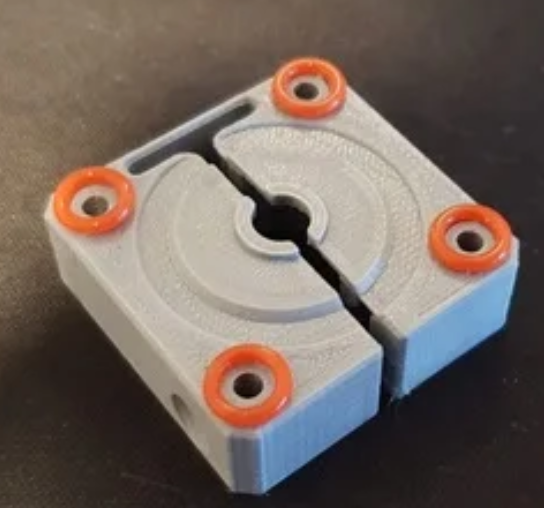
and last time I had to reassemble everything 2 hours of fiddling with screws were just too much there's btw a part that supposedly work better, it adds 4 o-rings. Have not tried but if you can get the o-rings might worth the try.
https://www.thingiverse.com/thing:3122283
-
-
Forgot one more thing, the top part, make sure you drill those holes so that screws can slide through them easily. The screws need to be biting only the bottom part, they need to be able to slide easily through the top part. Ideally, you should use screws that are threaded only at the bottom
")
-
undefined tekstyle referenced this topic 27 Jul 2022, 05:39
-
undefined tekstyle referenced this topic 27 Jul 2022, 05:40
-
undefined tekstyle referenced this topic 27 Jul 2022, 05:40