Not Homing correctly At all. and nozzle issues
-
@moe-adams9093 said in Not Homing correctly At all. and nozzle issues:
very slow to raise temp and it stops at 135c
either the thermistor is reporting the wrong temperature
or your heater is for the wrong voltage and you're effectively getting a fraction of the wattage you expect
or there is alot of losses in your wiring
or leprechauns; idk? -
@moe-adams9093 M122 Please.
FYI if you click the button that looks like </>, just above, you can paste your text in there.
iehttps://duet3d.dozuki.com/Wiki/Tuning_the_heater_temperature_controlMakes it easier to read!
Also, might worth checking the hotend connections, make sure the ferrules are tight. -
Can you post a photo of the hotend?
Is there something in direct physical contact with the heat block?
Is the fan blowing directly on the block without a silicone sock?
Perhaps the Ender 5 Plus is using a different thermistor than other creality hotends and your thermistor values are completely off. -
@Phaedrux hello can you please help me solve this issue so my ender 5 plus has 2 Zmotors and when I run G32 it doesn't compensate or level the bed very well it still off from corner to corner so I found that I need to set an independent Zmotors to get auto bed leveling up and running I connected first Z motor LeftSide to Z-drive and the second one right side to E1 I spent days reading the duet form but it's not working for me or I have no clue what I'm doing, if you please point me in the right direction that would be highly appreciated
here's my config.g file
; Configuration file for Duet Maestro (firmware version 2.03)
; executed by the firmware on start-up
;
; generated by RepRapFirmware Configuration Tool v2.1.8 on Thu Apr 30 2020 23:57:45 GMT-0500 (Central Daylight Time); General preferences
G90 ; send absolute coordinates...
M83 ; ...but relative extruder moves
M550 P"Ender5Plus" ; set printer name; Network
M552 P0.0.0.0 S1 ; enable network and acquire dynamic address via DHCP
M586 P0 S1 ; enable HTTP
M586 P1 S0 ; disable FTP
M586 P2 S0 ; disable Telnet; Drives
M569 P0 S1 ; physical drive 0 goes forwards
M569 P1 S1 ; physical drive 1 goes forwards
M569 P2 S0 ; physical drive 2 goes backwards
M569 P3 S0 ; physical drive 3 goes backwards
M584 X0 Y1 Z2 E3 ; set drive mapping
M350 X16 Y16 Z16 E16 I1 ; configure microstepping with interpolation
M92 X80.00 Y80.00 Z800.00 E96.00 ; set steps per mm
M566 X480.00 Y480.00 Z24.00 E300.00 ; set maximum instantaneous speed changes (mm/min)
M203 X30000.00 Y30000.00 Z600.00 E3000.00 ; set maximum speeds (mm/min)
M201 X500.00 Y500.00 Z100.00 E5000.00 ; set accelerations (mm/s^2)
M906 X960 Y980 Z960 E960 I30 ; set motor currents (mA) and motor idle factor in per cent
M84 S30 ; Set idle timeout; Axis Limits
M208 X0 Y0 Z0 S1 ; set axis minima
M208 X365 Y365 Z415 S0 ; set axis maxima; Endstops
M574 X1 Y1 S1 ; set active low and disabled endstops
M574 Z1 S2 ; set endstops controlled by probe; Z-Probe
M558 P9 H2 F120 T6000 ; set Z probe type to bltouch and the dive height + speeds
G31 P500 X0 Y0 Z2 ; set Z probe trigger value, offset and trigger height
M557 X5:350 Y5:350 S50 ; define mesh grid; Heaters
M141 H2 ;Assign chamber heater to heater 2
M307 H2 A11 C99000 D2000 B1 ; chamber heater operates in bang-bang mode
M305 P2 T10000 B3988 C0 R2200 ; Set thermistor + ADC parameters for bed
M143 H2 S80 ; set temperature limit for heater 2 to 80C
M305 P0 T98801 B4138 R2200 ; set thermistor + ADC parameters for heater 0
M143 H0 S130 ; set temperature limit for heater 0 to 130C
M305 P1 T98801 B4138 R2200 ; set thermistor + ADC parameters for heater 1
M143 H1 S300 ; set temperature limit for heater 1 to 300C; Fans
M106 P0 S0.2 I0 F500 H1 T45 ; set fan 0 value, PWM signal inversion and frequency. Thermostatic control is turned on
M106 P1 S0.2 I0 F500 H1 T45 ; set fan 1 value, PWM signal inversion and frequency. Thermostatic control is turned on; Tools
M563 P0 S"Nozzle" D0 H1 F0 ; define tool 0
G10 P0 X0 Y0 Z0 ; set tool 0 axis offsets
G10 P0 R0 S0 ; set initial tool 0 active and standby temperatures to 0C; Custom settings are not defined
; Miscellaneous
M501 ; load saved parameters from non-volatile memory
M911 S10 R11 P"M913 X0 Y0 G91 M83 G1 Z3 E-5 F1000" ; set voltage thresholds and actions to run on power loss
T0 ; select first tool
bed file
bed.g
; called to perform automatic bed compensation via G32
;
; generated by RepRapFirmware Configuration Tool v2.1.8 on Thu Apr 30 2020 23:57:44 GMT-0500 (Central Daylight Time)
M561 ; clear any bed transform
G29 ; probe the bed and enable compensation
; homez.g
; called to home the Z axis
;
; generated by RepRapFirmware Configuration Tool v2.1.8 on Fri May 01 2020 00:50:10 GMT-0500 (Central Daylight Time)
G91 ; relative positioning
G1 H2 Z2 F6000 ; lift Z relative to current position
G90 ; absolute positioning
G1 X5 Y5 F6000 ; go to first probe point
G30 ; home Z by probing the bed; Uncomment the following lines to lift Z after probing
;G91 ; relative positioning
;G1 Z2 F100 ; lift Z relative to current position
;G90 ; absolute positioning
so when I added this code to config.g file
M584 X0 Y1 Z2:4 E3; two Z motors connected to driver outputs Z and E1
M671 X-20:220 Y0:0 S0.5 ; leadscrews at left (connected to Z) and right (connected to E1) of X axis
M208 X-5:205 Y0:200 ; X carriage moves from -5 to 205, Y bed goes from 0 to 200it didnt work right at all
please help if you can thank you
-
@moe-adams9093 said in Not Homing correctly At all. and nozzle issues:
; Drives
M569 P0 S1 ; physical drive 0 goes forwards
M569 P1 S1 ; physical drive 1 goes forwards
M569 P2 S0 ; physical drive 2 goes backwards
M569 P3 S0 ; physical drive 3 goes backwards
M584 X0 Y1 Z2 E3 ; set drive mappingYou're going to need to define drive 4 for use as a second Z axis in config.g and change your bed.g to do the probing for the leveling adjustment.
; Drives
M569 P0 S1 ; physical drive 0 goes forwards (X axis)
M569 P1 S1 ; physical drive 1 goes forwards (Y axis)
M569 P2 S0 ; physical drive 2 goes backwards (Z1 axis)
M569 P3 S0 ; physical drive 3 goes backwards (E axis)
M569 P4 S0 ; physical drive 4 goes backwards (Z2 axis)
M584 X0 Y1 Z2:4 E3 ; set drive mapping
M671 X-20:220 Y0:0 S0.5 ; leadscrews at left (connected to Z) and right (connected to E1) of X axis
For the points in M671 you need to find the coordinates of your own bed to measure, you can't just use the example points.
You will connect one Z motor to the Z1 (drive 2), put the jumpers back in the second port. Then connect the other Z motor to the E1 (drive 4)
For bed.g you'll also have to find the points to probe with G30
G28 ; home
M401 ; deploy Z probe (omit if using bltouch)
G30 P0 X20 Y100 Z-99999 ; probe near a leadscrew, half way along Y axis
G30 P1 X180 Y100 Z-99999 S2 ; probe near a leadscrew and calibrate 2 motors
M402 ; retract probe (omit if using bltouch)
The G30 P1 will likely be further to the right on your larger bed so adjust the CX position accordingly.
-
Thank you very much for all your help. I will make these adjustments tomorrow, but how can I find points in M671 coordinates of my own bed measuring, is their sort of documentation can explain how to find the coordinate positions of my bed. thank you again
-
You just need to choose a point close to the lead screw but still on the bed and both need to be in line on the Y axis.
-
@Phaedrux said in Not Homing correctly At all. and nozzle issues:
G28 ; home M401 ; deploy Z probe (omit if using bltouch) G30 P0 X20 Y100 Z-99999 ; probe near a leadscrew, half way along Y axis G30 P1 X180 Y100 Z-99999 S2 ; probe near a leadscrew and calibrate 2 motors M402 ; retract probe (omit if using bltouch)
THANK YOU. it worked and I found my correct bed coordinate points. do I have to change any config for my BLtouch current settings are
Z-Probe
M558 P9 H2 F120 T6000 ; set Z probe type to bltouch and the dive height + speeds
G31 P500 X0 Y0 Z2 ; set Z probe trigger value, offset and trigger height
M557 X5:350 Y5:350 S50 ; define mesh grid
I have version 3 -
The dive height is a little low. It should be at least a mm more than the trigger height. Try M558 H3
Also change G31 P500 to G31 P25
Have you calibrated our probe and measured the offsets yet?
https://duet3d.dozuki.com/Wiki/Test_and_calibrate_the_Z_probe
-
so I have adjusted all the settings accordingly here's a photo of the hight map
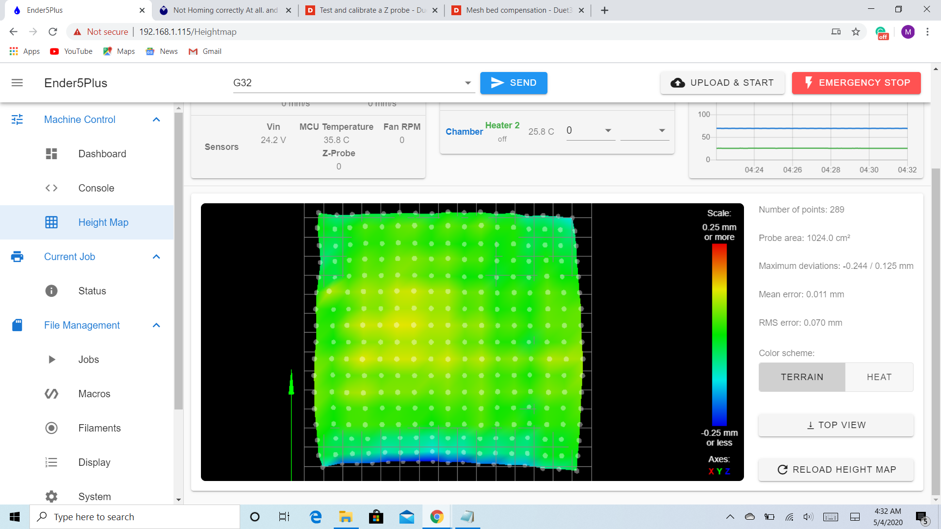 so I don't if that's ok or it should be 0 all the way I tried to print a file 340 x 340 and it looks like it's not adjusting probably. here's my updated file config.g
; Configuration file for Duet Maestro (firmware version 2.03)
; executed by the firmware on start-up
;
; generated by RepRapFirmware Configuration Tool v2.1.8 on Thu Apr 30 2020 23:57:45 GMT-0500 (Central Daylight Time); General preferences
G90 ; send absolute coordinates...
M83 ; ...but relative extruder moves
M550 P"Ender5Plus" ; set printer name; Network
M552 P0.0.0.0 S1 ; enable network and acquire dynamic address via DHCP
M586 P0 S1 ; enable HTTP
M586 P1 S0 ; disable FTP
M586 P2 S0 ; disable Telnet; Drives
M569 P0 S1 ; physical drive 0 goes forwards
M569 P1 S1 ; physical drive 1 goes forwards
M569 P2 S0 ; physical drive 2 goes backwards
M569 P3 S0 ; physical drive 3 goes backwards
M569 P4 S0 ; physical drive 4 goes backwards (Z2 axis)
M584 X0 Y1 Z2:4 E3 ; set drive mapping
M671 X0:285 Y0:180 S0.5 ; leadscrews at left (connected to Z) and right (connected to E1) of X axis
M350 X16 Y16 Z16 E16 I1 ; configure microstepping with interpolation
M92 X80.00 Y80.00 Z800.00 E96.00 ; set steps per mm
M566 X480.00 Y480.00 Z24.00 E300.00 ; set maximum instantaneous speed changes (mm/min)
M203 X30000.00 Y30000.00 Z600.00 E3000.00 ; set maximum speeds (mm/min)
M201 X500.00 Y500.00 Z100.00 E5000.00 ; set accelerations (mm/s^2)
M906 X960 Y980 Z960 E960 I30 ; set motor currents (mA) and motor idle factor in per cent
M84 S30 ; Set idle timeout; Axis Limits
M208 X0 Y0 Z0 S1 ; set axis minima
M208 X365 Y365 Z415 S0 ; set axis maxima; Endstops
M574 X1 Y1 S1 ; set active low and disabled endstops
M574 Z1 S2 ; set endstops controlled by probe; Z-Probe
M558 P9 H3 F120 T6000 ; set Z probe type to bltouch and the dive height + speeds
G31 P25 X0 Y0 Z1.758 ; set Z probe trigger value, offset and trigger height
M557 X5:335 Y5:335 S20 ; define mesh grid; Heaters
M141 H2 ;Assign chamber heater to heater 2
M307 H2 A11 C99000 D2000 B1 ; chamber heater operates in bang-bang mode
M305 P2 T10000 B3988 C0 R2200 ; Set thermistor + ADC parameters for bed
M143 H2 S80 ; set temperature limit for heater 2 to 80C
M305 P0 T98801 B4138 R2200 ; set thermistor + ADC parameters for heater 0
M143 H0 S130 ; set temperature limit for heater 0 to 130C
M305 P1 T98801 B4138 R2200 ; set thermistor + ADC parameters for heater 1
M143 H1 S300 ; set temperature limit for heater 1 to 300C; Fans
M106 P0 S0.5 I0 F500 H1 T45 ; set fan 0 value, PWM signal inversion and frequency. Thermostatic control is turned on
M106 P1 S0.5 I0 F500 H1 T45 ; set fan 1 value, PWM signal inversion and frequency. Thermostatic control is turned on; Tools
M563 P0 S"Nozzle" D0 H1 F0 ; define tool 0
G10 P0 X0 Y0 Z0 ; set tool 0 axis offsets
G10 P0 R0 S0 ; set initial tool 0 active and standby temperatures to 0C; Custom settings are not defined
; Miscellaneous
M501 ; load saved parameters from non-volatile memory
M911 S10 R11 P"M913 X0 Y0 G91 M83 G1 Z3 E-5 F1000" ; set voltage thresholds and actions to run on power loss
T0 ; select first tooland file bed.g
; bed.gG28 ; home
M401 ; deploy Z probe (omit if using bltouch)
G30 P0 X0 Y180 Z-99999 ; probe near a leadscrew, half way along Y axis
G30 P1 X285 Y180 Z-99999 S2 ; probe near a leadscrew and calibrate 2 motors
M402 ; retract probe (omit if using bltouch)G29 S0
G29 S1I don't know if i have to enable some settings to run hight map while it prints maybe from slicer or from DWC. thank you for all your help
-
when I run G32 here's the message I get
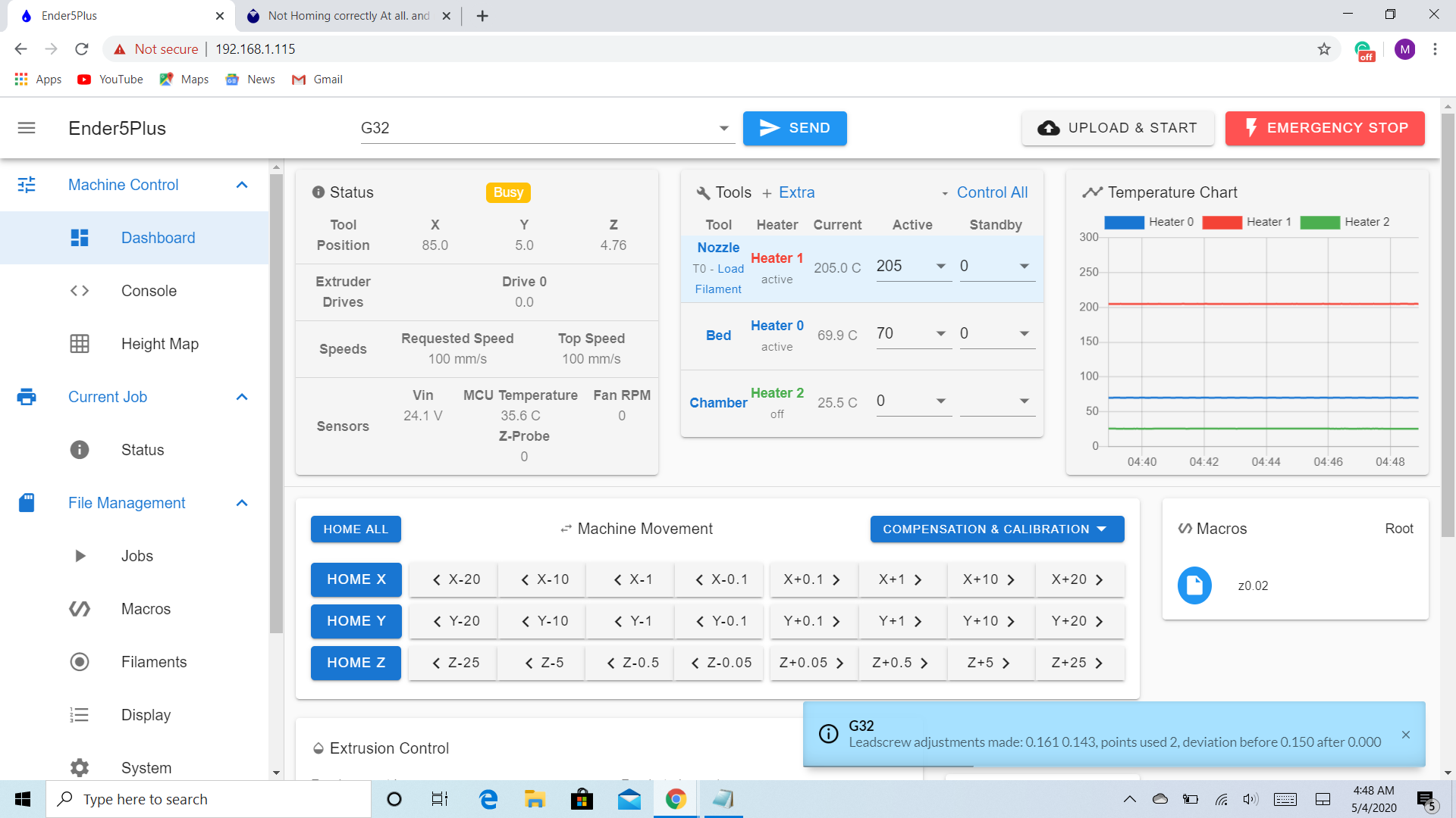
does that meat its successfully calibrated. -
also here's the message when I run G29.
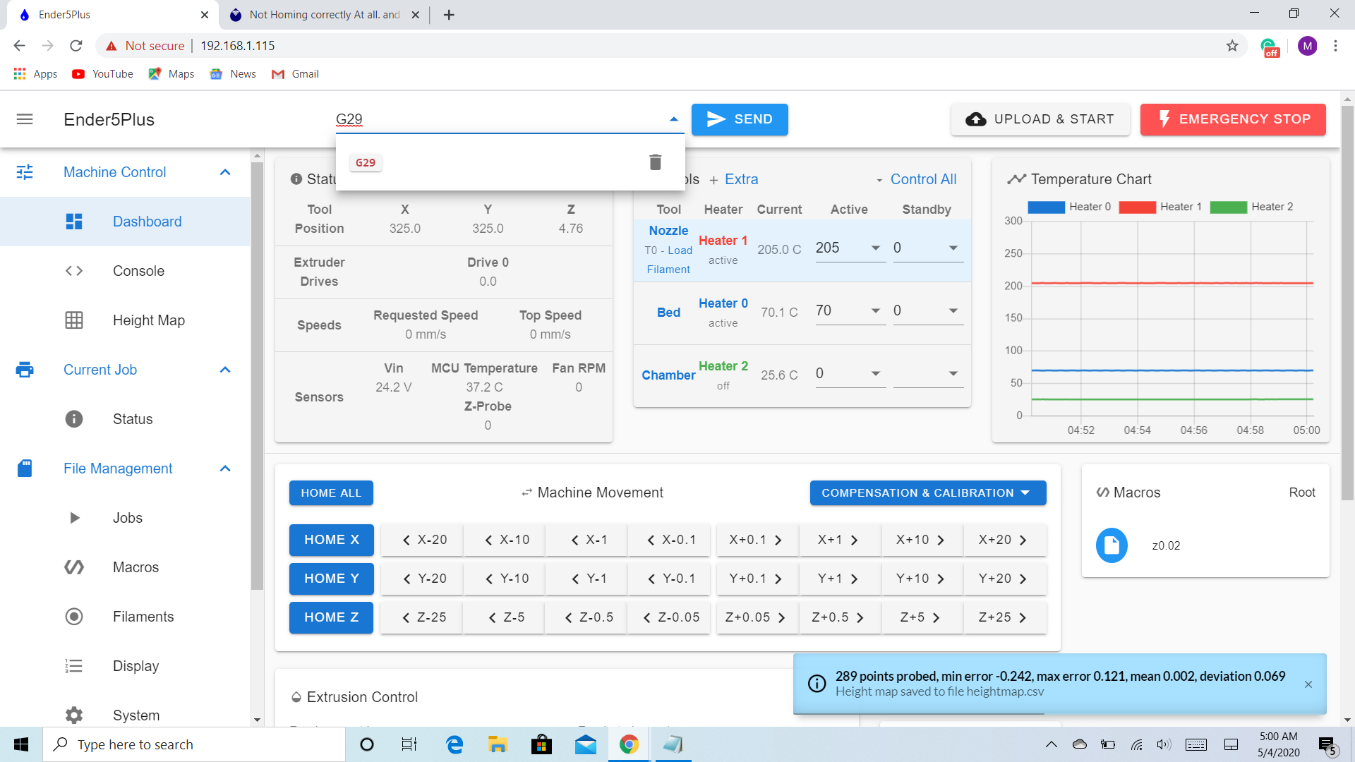
please let me know if that looks good sorry I know I have been asking you a lot. Thanks again -
Print a test file like this one with mesh enabled and again disabled. You should be able to tell if it's being applied correctly.
-
Yes I did what you told me and it looks like its not working properly. Any other suggestions would be helpful. Thanks
-
@moe-adams9093 What slicer are you using? Please post your start GCode from your slicer.
Regards,
Paul -
@moe-adams9093 said in Not Homing correctly At all. and nozzle issues:
G31 P25 X0 Y0 Z1.758
You need to measure your X and Y probe offset otherwise the corrections will be off in X Y position.
The heightmap itself looks ok. After measuring the offset redo the G29 and reprint the test file to see if it's behaving better.
-
Thank you for the additional information so my x offset is 44mm and the y offset is -5mm but when I try to run mesh compensation its starting from 44 to 285 and my actual build volume is 350 x 350 so please correct me on that one am I loosing that left over space since it only probing from 44 to 285. Also when I checked my old configuration from the original bord it says offest x0 y0 z1.78 so I don't if that does matter or not. Please let me know thank you
