Possible PWM port issue & RRF3 Question
-
@Phaedrux that is the RRF Config output! Lol That’s why I was confused. I could have selected the wrong setting somewhere.
Thanks for the link, I’ll dig in after the kiddos go to bed. -
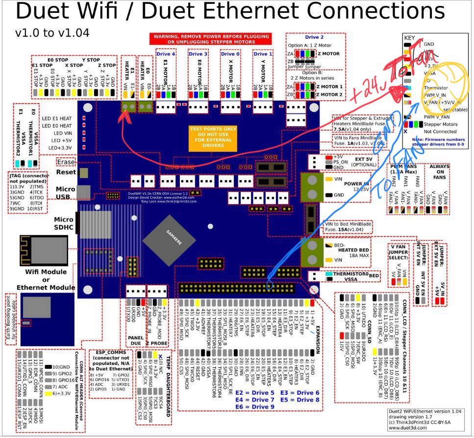
@Phaedrux When you tag into E1 heater and Heater 7, just to clarify, I would hook up to E1 to the positive lead to fan. Then I would hook up "13) heater4" (as an example) pin to the negative lead of the fan?
-
@jallen810 said in Possible PWM port issue & RRF3 Question:
I could have selected the wrong setting somewhere.
Post your config.g then. Maybe you had RRF2 selected?
I'm not sure what you mean by this.
When you tag into E1 heater and Heater 7, just to clarify, I would hook up to E1 to the positive lead to fan. Then I would hook up "13) heater4" (as an example) pin to the negative lead of the fan?
-
@Phaedrux I had a blonde moment, I can't use a normal 2pin fan can I?
I need a 3+ wire fan right? (sorry never actually used PWM function of fans before)My artillery sidewinder specs:
Xaxis: homes at 0, left side (Panasonic GL8H optical NPN NC sensor)
Yaxis: homes at back, but 0 is actually at the front (Panasonic GL8H optical NPN NC sensor)
Z = Inductive ABL probe (Panasonic GXHL15A NPN NC sensor)Lastly, here is my RRFconfigurator custom config.g for RRF3.1:
; Configuration file for Duet WiFi (firmware version 3) ; executed by the firmware on start-up ; ; generated by RepRapFirmware Configuration Tool v3.1.4 on Sat Aug 15 2020 15:29:14 GMT-0400 (EDT) ; General preferences G90 ; send absolute coordinates... M83 ; ...but relative extruder moves M550 P"Sidewinder X1 RRF3" ; set printer name ; Network M552 S0 M552 S1 P192.168.1.50 ; Assign fixed IP address M553 P255.255.255.0 ; Assign Netmask to match my network M554 P192.168.1.1 ; Assign Gateway IP address to match network M552 S1 ; enable network M586 P0 S1 ; enable HTTP M586 P1 S0 ; disable FTP M586 P2 S0 ; disable Telnet ; Drives M569 P0 S1 ; physical drive 0 goes forwards M569 P1 S0 ; physical drive 1 goes backwards M569 P2 S0 ; physical drive 2 goes backwards M569 P3 S0 ; physical drive 3 goes backwards M584 X0 Y1 Z2 E3 ; set drive mapping M350 X16 Y16 Z16 E16 I1 ; configure microstepping with interpolation M92 X80.00 Y80.00 Z400.00 E415.00 ; set steps per mm M566 X900.00 Y900.00 Z60.00 E1200.00 ; set maximum instantaneous speed changes (mm/min) M203 X9000.00 Y9000.00 Z1500.00 E3000.00 ; set maximum speeds (mm/min) M201 X500.00 Y500.00 Z20.00 E166.67 ; set accelerations (mm/s^2) M906 X800 Y800 Z800 E800 I30 ; set motor currents (mA) and motor idle factor in per cent M84 S30 ; Set idle timeout ; Axis Limits M208 X0 Y0 Z0 S1 ; set axis minima M208 X300 Y340 Z400 S0 ; set axis maxima ; Endstops M574 X2 S1 P"xstop" ; configure active-high endstop for high end on X via pin xstop M574 Y2 S1 P"ystop" ; configure active-high endstop for high end on Y via pin ystop M574 Z2 S2 ; configure Z-probe endstop for high end on Z ; Z-Probe M558 P1 C"zprobe.in" H5 F600 T6000 ; set Z probe type to unmodulated and the dive height + speeds G31 P1000 X40 Y-41 Z2.5 ; set Z probe trigger value, offset and trigger height M557 X45:295 Y10:280 S40 ; define mesh grid ; Heaters M308 S0 P"bedtemp" Y"thermistor" T100000 B4138 ; configure sensor 0 as thermistor on pin bedtemp M950 H0 C"bedheat" T0 ; create bed heater output on bedheat and map it to sensor 0 M307 H0 B1 S1.00 ; enable bang-bang mode for the bed heater and set PWM limit M140 H0 ; map heated bed to heater 0 M143 H0 S130 ; set temperature limit for heater 0 to 130C M308 S1 P"e0temp" Y"thermistor" T500000 B4723 C1.19622e-7 ; configure sensor 1 as thermistor on pin e0temp M950 H1 C"e0heat" T1 ; create nozzle heater output on e0heat and map it to sensor 1 M307 H1 B0 S1.00 ; disable bang-bang mode for heater and set PWM limit ; Fans M950 F0 C"fan0" Q500 ; create fan 0 on pin fan0 and set its frequency M106 P0 C"Layer Fan 1" S0 H-1 ; set fan 0 name and value. Thermostatic control is turned off M950 F1 C"fan1" Q500 ; create fan 1 on pin fan1 and set its frequency M106 P1 C"HE Fan 2" S1 H1 T45 ; set fan 1 name and value. Thermostatic control is turned on ; Tools M563 P0 D0 H1 F0 ; define tool 0 G10 P0 X0 Y0 Z0 ; set tool 0 axis offsets G10 P0 R0 S0 ; set initial tool 0 active and standby temperatures to 0C ; Custom settings are not defined ; Miscellaneous M575 P1 S1 B57600 ; enable support for PanelDue M501 ; load saved parameters from non-volatile memory M911 S10 R11 P"M913 X0 Y0 G91 M83 G1 Z3 E-5 F1000" ; set voltage thresholds and actions to run on power loss and for reference, here is the back up of the RRF2.03. config.g that I made just before updating to RRF3 this afternoon:
; Configuration file for Duet WiFi (firmware version 2.03) ; executed by the firmware on start-up ; ; generated by RepRapFirmware Configuration Tool v2.1.8 on Sat Apr 11 2020 14:47:32 GMT-0400 (Eastern Daylight Time) ; Revised by Jake Allen on 4.18.2020 @ 10:30am EST ;-----General preferences----------------------------------------------------------------------------------------------------------------- G90 ; send absolute coordinates... M83 ; ...but relative extruder moves M550 P"Sidewinder X1" ; set printer name ;-----Network---------------------------------------------------------------------------------------------------------------------------- M552 S0 ;M552 S1 P192.168.1.50 ; Assign fixed IP address M553 P255.255.255.0 ; Assign Netmask to match my network M554 P192.168.1.1 ; Assign Gateway IP address to match network M552 S1 ; enable network M586 P0 S1 ; enable HTTP M586 P1 S0 ; disable FTP M586 P2 S0 ; disable Telnet ;-----Drives----------------------------------------------------------------------------------------------------------------------------- M569 P0 S0 D2 ; (X-Axis) drive 0 goes forwards (Jake wrong config M569 P0 S1) M569 P1 S1 D2 ; (Y-Axis) drive 1 goes forwards M569 P2 S1 D2 ; (Z-Axis) drive 2 goes forwards M569 P3 S1 D2 ; (Extruder) drive 3 goes backward with Bondtech (titan = S0, Bondtech = S1) M584 X0 Y1 Z2 E3 ; set drive mapping M350 X16 Y16 Z16 E16 I1 ; configure micro-stepping with interpolation M92 X80.12 Y80.12 Z399.78 E415.0 ; set steps per mm (from Jake's Marlin Setup) (titan=446mm) M566 X800.00 Y980.00 Z60.00 E2500.00 ; set maximum instantaneous speed changes (mm/min) --> E180 to E2500, Z12 to Z60 M203 X9000.00 Y9000.00 Z1500.00 E3000.00 ; set maximum speeds (mm/min) --> X&Y from 6000 (100mm/s) to 9000 (150mm/s) M201 X800.00 Y800.00 Z400.00 E10000.00 ; set accelerations (mm/s^2) E10000 M906 X800 Y800 Z800 E800 I30 ; set motor currents (mA) and motor idle factor in per cent M84 S30 ; Set idle timeout ;-----Axis Limits------------------------------------------------------------------------------------------------------------------------ M208 X0 Y0 Z0 S1 ; set axis minima M208 X300 Y340 Z400 S0 ; set axis maxima (Changed Y from 300 to 345 to compensate for offset) ;-----Endstops--------------------------------------------------------------------------------------------------------------------------- M574 X1 Y1 S0 ; set active low and disabled endstops (To enable Z-endstop add "Z1 or Z2" after y M574 Z1 S2 ; Define Z to use probe. S2=Home to min ;-----Z-Probe (BLtouch)------------------------------------------------------------------------------------------------------------------ M307 H3 A-1 C-1 D-1 ; (Duet3d method) disable Heater7 to free up PWM channel 5 on Duex board for BLTouch M558 P5 H5 F600 A1 I1 ; GLH8 EndstopABL, Mode P=5, StartProbeH=5mm, Speed=300mm/min, #probes A=3, Invert signal for Endstop I=1 ;BLTOUCH; M558 P9 H5 F100 T9000 ; (Duet3D method) P=Select Z-probe mode=9 BLtouch. H=DiveHeight abv bed(mm), F=Speed bed moves, T=TravelSpeed btwn pts G31 P25 X40 Y-41 Z1.385 ; P=Z probe trigger value,X&Y=offset mount relative to nozzle (mm), Z=trigger height 1.84 ;(4020 Mosquito J&L Mount + HL15 Zoff=0.7mm, x=40, y=-41) ;(M18 probe,z=1.85mm, x=40, y=-50) ;Stock z-end=0.58 ; Change P500 to P25 and X&Y=0 to X=40 & Y=-38 for probe offset vs. nozzle (3DChanh X58 Y-36) M557 X45:295 Y10:280 S40 ; define mesh grid (S20 = 143 points, S45 = 36pts) (Prev: M557 X15:285 Y15:285) ; Change X0:225 Y45:300 S45 to--> M557 X60:300 Y0:260 S20, S20=156pts, try S24 & S40 =100 & 36pts, Previously S=30 ;-----Heaters---------------------------------------------------------------------------------------------------------------------------- M140 H0 ; remap heated bed to heater 1 M307 H0 B1 S1.00 ; enable bang-bang mode for the bed heater and set PWM limit M305 P0 T100000 B4138 R4700 ; set Bed thermistor + ADC parameters for heater 0 M143 H0 S125 ; set temperature limit for heater 0 to 125C ;M305 P1 T100000 B4138 R4700 ;104GT E3D thermistor set thermistor + ADC parameters for heater 1 M305 P1 T500000 B4723 C1.196220e-7 H20 ; Slice Engr 450°C thermistor Set thermistor +ADC parameters for H1 M143 H1 S320 ; set temperature limit for heater 1 to 300C ;-----Fans-------------------------------------------------------------------------------------------------------------------------------- M106 P1 S0 H-1 C"Layer_Fan" F500 ; Part Cool Layer Fan (8.14.20 blew Mosfets, some cntl Fan1 port so remapped) ;M106 P1 S1 H1 T45 C"Heatsink_Fan" F500 ; Hotend Heatsink Fan ;M106 P2 S0.75 H0 T45 C"BoardCool" F500 ; Ducted 4020 DuetBoard Cooling Fan, Bed=45c turn on fan 75% ;-----Tools------------------------------------------------------------------------------------------------------------------------------- M563 P0 S"HOTEND" D0 H1 F1 ; define tool 0 (8.14.20 change from F0 to F1 bc of blown mosfet remap) G10 P0 X0 Y0 Z0 ; set tool 0 axis offsets G10 P0 R0 S0 ; set initial tool 0 active and standby temperatures to 0C ; Custom settings are not defined ;-----Miscellaneous----------------------------------------------------------------------------------------------------------------------- M501 ; load saved parameters from non-volatile memory M911 S10 R11 P"M913 X0 Y0 G91 M83 G1 Z3 E-5 F1000" ; set voltage thresholds and actions to run on power loss T0 ; select first tool -
@jallen810 said in Possible PWM port issue & RRF3 Question:
I had a blonde moment, I can't use a normal 2pin fan can I?
I need a 3+ wire fan right? (sorry never actually used PWM function of fans before)to use with E1 output? you can use 2 pin fan. 3pin fans have tachometer for RPM feedback, 4pin fans have PWM input but i'd hesitate to drive the PWM input from a pin on the duet without doin some research
-
@bearer okay so @Phaedrux said I can tag into the E1 heater for the 24v and then pick a heater pin on the expansion slot. My question is how do I actually physically wire this thing up?
Red wire [from fan +V] ---> Heater4 (pin13)
Black wire [from fan -V] ----> E1+24vLike this:
-
@jallen810 said in Possible PWM port issue & RRF3 Question:
So... I have a question, why are the PWM fan ports not protected by a fuse? The only issues I have ever had with this board has been these MOSFETs . I love this board, but this is a serious Debbie Downer...
They are, on version 1.03 and later boards... but sadly fuses blow much more slowly than mosfets do.
On later production we've switched to mosfets with a higher peak current rating, although that's unlikely to help when the output is shorted.
-
@jallen810 said in Possible PWM port issue & RRF3 Question:
Red wire [from fan +V] ---> Heater4 (pin13)
Black wire [from fan -V] ----> E1+24vboth wires to E1 output if the fan is 24v.
red wire to Vin
black wire to E1-
(E1- is switched to ground when the output is enabled, to use heater4 or any of the other pins on the expansion you'll need an external mosfet to sink more current than the microcontroller can handle) -
Just in case it wasn't totally clear, both fan wires will go the the E1 heater connector.
Then in your config.g you would need the follow assuming you're going to use it as Fan0.
Where you have:
M950 F0 C"fan0" Q500you would change it toM950 F0 C"e1heat" Q500The pin name e1heat comes from this list: https://duet3d.dozuki.com/Wiki/RepRapFirmware_3_overview#Section_Pin_names_for_Duet_2_WiFi_Ethernet
-
@Phaedrux so I talked with @bearer and he explained this and we tested my wiring across E1vin and mains negative. Fan worked, wiring correct.
1.) Then I hooked up fan negative to E1negative and changed the config line u said above.
Powered up and nothing, using fan control on both DWC and PanelDue are non responsive. my E1 LED is not lighting up. It’s almost like we forgot to associate something? Ideas?2.) Also, we’re you able to see anything in the config I posted that would suggest why my probe isn’t working and why my homing isn’t working?
3.) Lastly, I’ve tested X,Y,Z movement. Y & Z work as expected. But X only moves in the negative direction (left as it is configured currently) it does not respond when asked to move +x. Does this mean I swapped one of my stepper wire pairs? How do i identify and test that without blowing something up? -
Can you post the changes you've made for the fan?
Well your probe settings from your 3.1.1 and 2.03 are very different. One is using probe type P1 and the other P5. What I'm not familiar with probe you list, but if it worked with P5 before it should work with P5 in RRF3. So try to compare and match your settings. The only major difference between RRF2 and RRF3 there is the pin name is now included in the M558.
For your x movement problem, it could be a case of motor rotation direction or incorrect homing switch location.
In your 2.03 config your endstops are configured as low end, but in your 3.1.1 config you have them listed as high end. Which is it?
-
@Phaedrux i tested the TR8 mosfet for E1 and i only get 4.5v out of it. my guess it was also blown. @bearer is helping setup external mosfets to control my fans via the 50pin expansion header. I think i am set there.
I played with the probe settings after noticing the same things u just mentioned.
I tried both probe types 1 & 5, I tried inverting the signal with a "!" in front of the C var, i tried changing the end stops for XYZ from 0, 1, 2.
Nothing works, the only thing i notice is the probe reading is 1000 for P1 and 983 for P5 when no metal is present (probe light off). When i put a metal object under it, the reading drops to ~20.
It acts this way for every permutation of the above code changes.
I know this, my optical sensors were wired in RRF2 to the same pin as they are now, just ~1m extra wire in between. These sensors have to run 5v+, not 3.3v per the way the OEM wired them. But if i download the sensor Mfgr's data sheet it says, it needs 12-24v in. GL_8H Sidewinder X1 Endstops Data Sheet.pdfDo you suppose the extra length of wire causes enough resistance that the 5v that previously worked, now is not sufficient? If so, i could re-wire to pull off the main's power in... just a lot of extra work that i may not need to do...
-
@jallen810 said in Possible PWM port issue & RRF3 Question:
When i put a metal object under it, the reading drops to ~20.
I think that would be the inversion, so you'd need the ! in the pin name.
You might also need the pullup resistor enabled by adding a
^to the pin nameM558 P5 C"!^zprobe.in" H5 F600 T6000 -
@Phaedrux okay I will try that, what exactly is the application for this pull up resistor? Could it be the reason my endstops are acting funny?
It almost acts like the machine thinks it’s homes as soon as I push the home button... very weird.My homex,y,z and all fills are updated from S to H.. so that looks fine... any other ideas other than I just need to try running 24v of power to them?
-
@jallen810 A pull-up (or pull-down) resistor is a resistor used to ensure a known state for a signal. A switch should either send a 3.3V, or be connected to GND (0V), but some switches 'float' and give a partial voltage, which can lead to unexpected triggering. A pull up resistor will make sure that voltage is 3.3V. However, I don't think this is your issue.
Your probe:
Old RRF2 config:M558 P5 H5 F600 A1 I1The 'I1' means the probe is inverted. A1 is the number of times the probe will probe each point (1 is default). No travel speed 'T' set.
New RRF3 config:M558 P1 C"zprobe.in" H5 F600 T6000Wrong probe type, not inverted. Try:M558 P5 C"!zprobe.in" H5 F600 T6000See https://duet3d.dozuki.com/Wiki/Gcode?revisionid=HEAD#Section_M558_Set_Z_probe_type for details.
Your endstops:
Old RRF2 config:M574 X1 Y1 S0endstops on low end, S0 means active low
New RRF3 config:M574 X2 S1 P"xstop"andM574 Y2 S1 P"ystop"
Both set at wrong end (X2 and Y2 should be X1 and Y1, unless you've changed the position). S1 is fine (says it's a microswitch), but needs to be inverted. Try:M574 X1 S1 P"!xstop" M574 Y1 S1 P"!ystop" See https://duet3d.dozuki.com/Wiki/Gcode?revisionid=HEAD#Section_M574_RepRapFirmware_Num_3 and https://duet3d.dozuki.com/Wiki/Connecting_endstop_switches for details.
Ian
-
@droftarts @Phaedrux @bearer
Thank you all for your help with this upgrade to RRF3, I did finally get everything working properly again! I am running my first print now! Woot woot!One last question to you @droftarts, I figured out that I had to invert my endstop signals ~2hr before your comment but I had to do the following:
CONFIG.g
;----Endstops-------------------------------------------------------------------------------------------------------------------------------------------------------------------------- M574 X1 S1 P"!xstop" ; configure active-low endstop for low end on X via pin xstop M574 Y1 S1 P"!ystop" ; configure active-low endstop for low end on Y via pin ystop M574 Z1 S2 ; configure Z-probe endstop for low end on Z HOMEX.g
; homex.g ; called to home the X axis ; ; generated by RepRapFirmware Configuration Tool v3.1.4 on Sat Aug 15 2020 15:29:15 GMT-0400 (EDT) G91 ; relative positioning G1 H2 Z5 F6000 ; lift Z relative to current position G1 H1 X-305 F1800 ; move quickly to X axis endstop and stop there (first pass) 305 G1 H2 X5 F6000 ; go back a few mm G1 H1 X-305 F360 ; move slowly to X axis endstop once more (second pass) G1 H2 Z-5 F6000 ; lower Z again G90 ; absolute positioning HOMEY.g
; homey.g ; called to home the Y axis ; ; generated by RepRapFirmware Configuration Tool v3.1.4 on Sat Aug 15 2020 15:29:15 GMT-0400 (EDT) G91 ; relative positioning G1 H2 Z5 F6000 ; lift Z relative to current position G1 H1 Y-340 F1800 ; move quickly to Y axis endstop and stop there (first pass) G1 H2 Y-5 F6000 ; go back a few mm G1 H1 Y-340 F360 ; move slowly to Y axis endstop once more (second pass) G1 H2 Z-5 F6000 ; lower Z again G90 ; absolute positioning Question is: Why did I have to switch my "home" coordinate for both X&Y from 305/340 to -305/-340 when I switched to RRF?
-
@jallen810 said in Possible PWM port issue & RRF3 Question:
Question is: Why did I have to switch my "home" coordinate for both X&Y from 305/340 to -305/-340 when I switched to RRF?
The question is, where are your endstops?
For X if its on the left side, it's at the low end and moves to the endstop would be negative.
For Y, if it's at the front, it's at the low end and moves to the endstop would be negative. And vice versa.
-
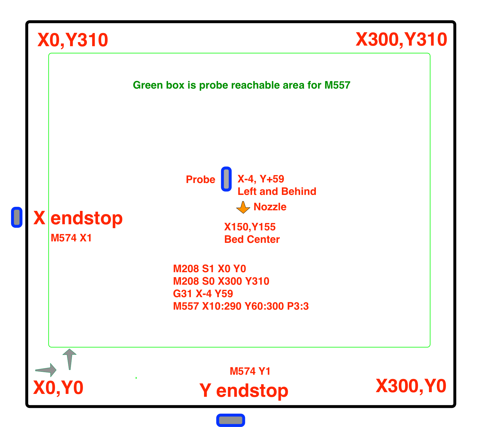
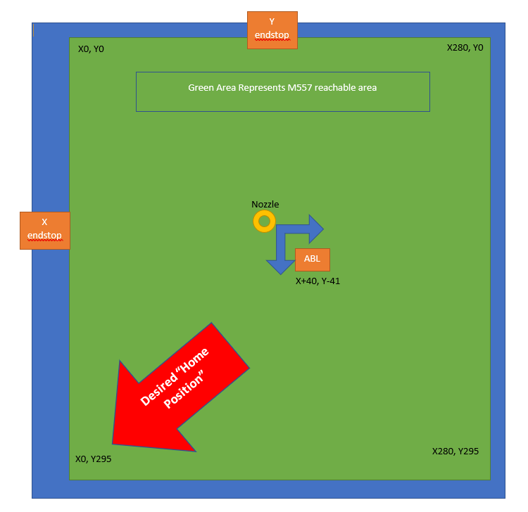
@Phaedrux here is how my bed is oriented, mind you, the code i placed above works as this diagram shows, it just doesn't make sense that is it not exactly the same as my RRF2.x was. It would seem that should not change from one to the next.
[Lastly, note i need to update my M557, i just noticed a typo when i was making this diagram") ]
]
-
@jallen810 You have a max Y endstop, and a minimum X endstop. Also, your drive direction assignments (S parameter in M569) are all different between your RRF2 and RRF3 configs:
RRF2;-----Drives----------------------------------------------------------------------------------------------------------------------------- M569 P0 S0 D2 ; (X-Axis) drive 0 goes forwards (Jake wrong config M569 P0 S1) M569 P1 S1 D2 ; (Y-Axis) drive 1 goes forwards M569 P2 S1 D2 ; (Z-Axis) drive 2 goes forwards M569 P3 S1 D2 ; (Extruder) drive 3 goes backward with Bondtech (titan = S0, Bondtech = S1) RRF3
; Drives M569 P0 S1 ; physical drive 0 goes forwards M569 P1 S0 ; physical drive 1 goes backwards M569 P2 S0 ; physical drive 2 goes backwards M569 P3 S0 ; physical drive 3 goes backwards So I think you have some additional sorting out to do, and that nothing has changed in behaviour between RRF2 and RRF3 in this respect. I think your RRF2 config was just wrong!
First, get your drives going the right way, by testing a +ve X move sends the nozzle to the right, and a +ve Y move sends the nozzle towards the back of the bed.
Then get the endstop settings correct. Should be:
M574 X1 S1 P"!xstop" M574 Y2 S1 P"!ystop" Lastly, your homeall.g and homey.g should change so that the large Y move is positive; the large X should stay negative. eg:
G91 ; relative positioning G1 H2 Z5 F6000 ; lift Z relative to current position G1 H1 Y340 F1800 ; move quickly to Y axis endstop and stop there (first pass) G1 H2 Y-5 F6000 ; go back a few mm G1 H1 Y340 F360 ; move slowly to Y axis endstop once more (second pass) G1 H2 Z-5 F6000 ; lower Z again G90 ; absolute positioning Ian
-
@jallen810 said in Possible PWM port issue & RRF3 Question:
here is how my bed is oriented, mind y
be careful of your slicer settings if you deviate from the normal cartesian layout shown by Phaedrux , you could easily end up with parts mirrored along one or more axes.