10th stepper driver from CONN LCD port
-
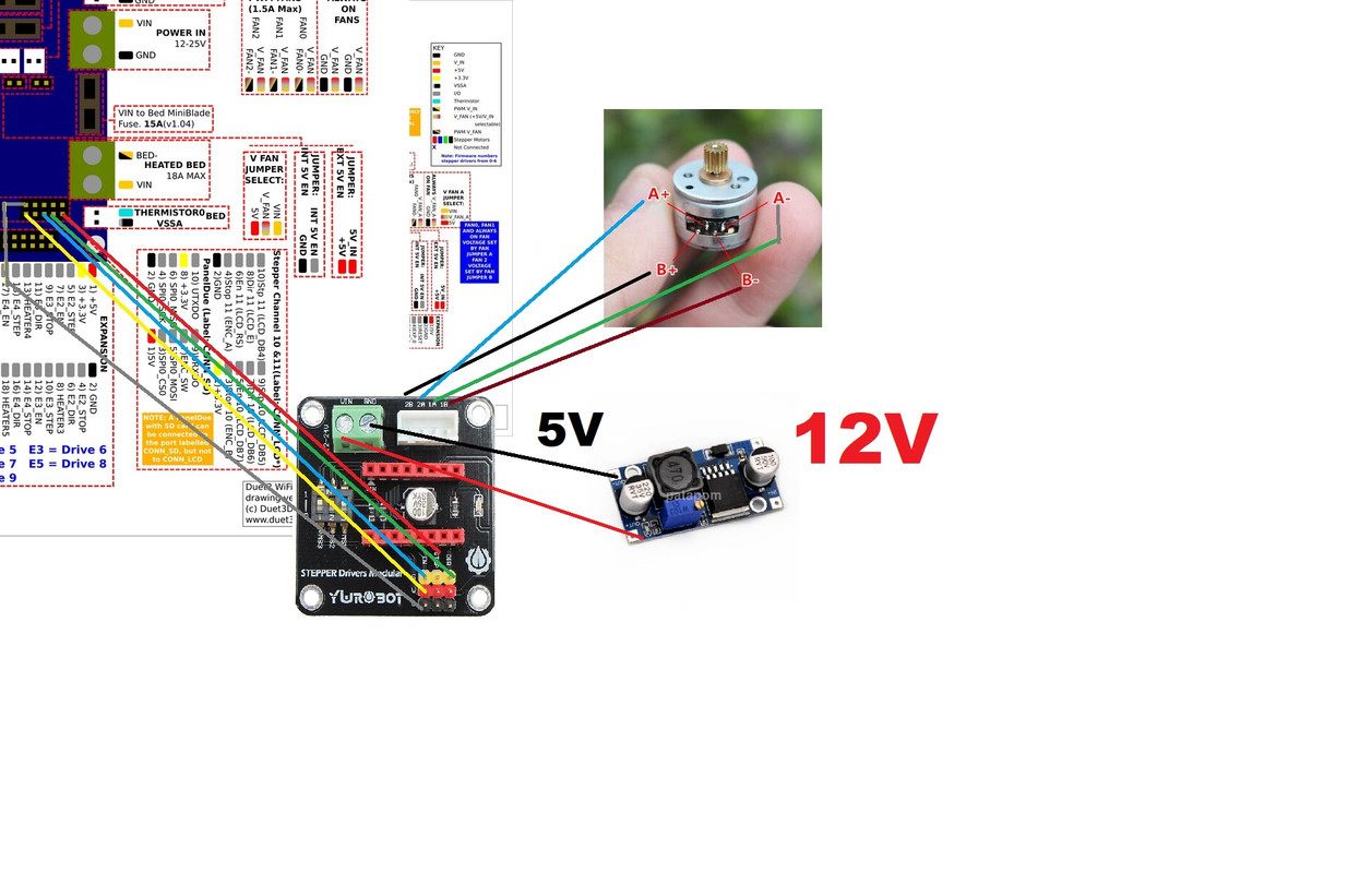
i am trying to connect a stepper driver to the CONN LCD pins but i can't get it to work. i have this motor attached to a stepper motor driver breakout board with a4988 driver and using a buck step-down converter to drop the voltage to the motor from 12V to 5V. Can someone help check out my configuration and see if it is set up correct? right not, i have all the stepper 10 pins hooked up (3 pins) and i have the V and G on the board going to the 3.3v and GND pin on the CONN LCD. issuing a G1 U10 does nothing. the motor body also gets really hot for doing nothing.
stepper motor used:
6.Gearbox gear ratio: 1:95.5 (about 1910 pulses the output shaft turn 360 degrees)
7.Step angle: motor is 18 degree;output shaft is about 0.188 degree
8.Stepper motor: 2-phase 4-wire
9.Phase resistance: 24.6 ohms
10.@6V short-circuit current: 0.23Abreakout board
https://www.reprap.me/3d-printer-42-stepper-motor-drive-expansion-board-8825-a4988.html; Drives
M569 P0 S0 ; physical drive 0 goes backwards
M569 P1 S0 ; physical drive 1 goes backwards
M569 P2 S0 ; physical drive 2 goes backwards
M569 P3 S0 ; physical drive 3 goes backwards
M569 P4 S0 ; physical drive 4 goes backwards
M569 P5 s0 ; physical drive 5 goes backwards
M569 P6 S0 ; physical drive 6 goes backwards
M569 P7 S0 ; physical drive 7 goes backwards
M569 P8 S0 ; physical drive 8 goes backwards
M569 P9 S0 ; physical drive 9 goes backwards
M569 P10 S0 ; physical drive 10 goes backwards CONN LCD #10 (tool changer)
M584 X0 Y1 Z2:3:4 E5:6:7:8:9 ; set drive mapping
M584 U10 ; set drive mapping U axis as CONN LCD #10 tool changer. uses E0 endstop by defaultM201 X3131.03 Y3131.03 z0 e1000 ; set max acceleration mm/s^2
m205 X100 Y100 E40 ; Set max instantaneous speed change (jerk) mm/s
M671 X20:400:20 Y20:141:330 s20 ; Z leadscrews are at (11,20), (411,141.7), (11,400). max correction 20mmM350 X16 Y16 Z16 U16 E16:16:16:16:16 I1 ; configure microstepping with interpolation
M92 X100.502 Y100.908 Z1600 U1186 E400:400:400:400:400 ; set steps per mm
M566 X900 Y900 Z12 U900 E120:120:120:120:120 ; set maximum instantaneous speed changes (mm/min)
M203 X6000 Y6000 Z180 U6000 E1200:1200:1200:1200:1200 ; set maximum speeds (mm/min)
M201 X500 Y500 Z20 U500 E850:850:850:850:850 ; set accelerations (mm/s^2)
M906 X1700 Y1700 Z1700 U0.0488 E595:595:595:595:595 I30 ; set motor currents (mA) and motor idle factor in percent
M84 S30 ; Set idle timeout; Axis Limits
M208 X-20 Y0 Z0 U0 S1 ; set axis minima
M208 X435 Y398 Z365 U50 S0 ; set axis maxima; Endstops
M574 X1 S1 P"xstop" ; configure active-high endstop for low end on X via pin xstop
M574 Y1 S1 P"ystop" ; configure active-high endstop for low end on Y via pin ystop
M574 Z1 S2 ; configure Z-probe endstop for low end on Z
M574 U1 S1 P"e0stop" ; configure active-high endstop for low end on U avia pin e0stop -
@tekstyle I'm assuming you've seen https://duet3d.dozuki.com/Wiki/Using_external_stepper_motor_drivers
Are you using an A4988 stepper driver (eg stepstick/Pololu-type) or something else? Whatever it is, have you checked that it works with a 5V input? The breakout board says 12-24V on it for input. Can you post a picture of your wiring?
In your config.g you have 2x M201 lines, and an M205 and M566 line (both set jerk, but mm/sec in M205, mm/min in M566). I'd comment out the earlier ones. Your M906 has an entry for U, set very low, and can be removed as the motor current is set on the stepper driver on the breakout board. However, I don't think these lines are what's stopping it.
It's a tiny motor, so hard to say what will actually make it turn. Look at the stepper driver (whichever it is) datasheet to check if it can output the low current this motor needs, with the input voltage used.
Ian
Bed-slinger - Mini5+ WiFi/1LC | RRP Fisher v1 - D2 WiFi | Polargraph - D2 WiFi | TronXY X5S - 6HC/Roto | CNC router - 6HC | Tractus3D T1250 - D2 Eth
-
yes, I am using a A4988 driver. I forgot to mention that. i have not checked if it works with 5V but how do I do that? according to the datasheet, I think it does? 3-5.5v?https://bangmuin.xyz/a4988-stepper-motor-driver-datasheet/
i'll edit those lines you mentioned when I get home. I might have missed the U parameter or have just copy and pasted twice when I was posting this. I'll also mess when the current without the gear reducer as well so i can see the shaft spin.
-
so i deleted the earlier extra lines. as well as the U# for the current. I can see a little movement on the motor but it still gets very hot . i'll try to adjust the knob on the A4988 driver but is there anyway I can test what the current Current is set at?
-
@tekstyle the A4988 is probably set such that it’s supplying way too much current for your little motor. You usually adjust the trimpot on the A4988 board, and measure the voltage between trimpot and ground to know what it’s set to. But what voltage you set it to depends on the driver board components. What board is it? Stepstick, Pololu, or random Chinese? See https://reprap.org/wiki/StepStick which has a lot of information about this. Post a good, close up photo of the A4988 board if you’re not sure.
Ian
-
@tekstyle also, looks like you wired the stepper motor wrong. Wire it 1A on the board to A+ on the motor, 1B to A-, 2A to B+, 2B to B-.
Ian
Bed-slinger - Mini5+ WiFi/1LC | RRP Fisher v1 - D2 WiFi | Polargraph - D2 WiFi | TronXY X5S - 6HC/Roto | CNC router - 6HC | Tractus3D T1250 - D2 Eth
-
i got this driver off a anycubic kossel mini used. most likely chinese generic stuff. however the R5 resistor shows "30C". i read most generic stuff are 0.1 ohm but according to a SMD resistor code calculator i found online, "30C" = 20K ohm. sigh
-
i adjusted the current to .1V. still gets hot but doesn't burn to the touch anymore like it used to. my new settings below. This seems to work fine. 1910mm would turn it 1 revolution as stated based on the gear ratio. I have played with different microstepping in hope of reducing the heat and increasing the speed with no luck. I might need to look for a new gearbox with a smaller reduction. the A4988 input voltage is 12V during this test. Thank you for your help!
M584 U10 ; set drive mapping U axis as CONN LCD #10 tool changer. uses E0 endstop by default
M671 X20:400:20 Y20:141:330 s20 ; Z leadscrews are at (11,20), (411,141.7), (11,400). max correction 20mm
M350 X16 Y16 Z16 E16:16:16:16:16 I1 ; configure microstepping with interpolation
;M350 U1 I0 ; configure microstepping without interpolation
M92 X100 Y100 Z1600 U0.5 E400:400:400:400:400 ; set steps per mm
M566 X900 Y900 Z12 U9999 E120:120:120:120:120 ; set maximum instantaneous speed changes (mm/min)
M203 X6000 Y6000 Z180 U99999 E1200:1200:1200:1200:1200 ; set maximum speeds (mm/min)
M201 X500 Y500 Z20 U9999 E850:850:850:850:850 ; set accelerations (mm/s^2)
M906 X1700 Y1700 Z1700 E595:595:595:595:595 I30 ; set motor currents (mA) and motor idle factor in percent
M84 S30 ; Set idle timeout -
@tekstyle it’s the sense resistor value that’s really important and they are hidden by the heatsink. As you’re running it at such a low current, that won’t be doing anything (will barely do anything at high current either), so take it off and take another photo.
Did you need to rewire the motor wires to get it to work?
A motor that small isn’t going to have much performance, and possibly the stepper driver is having problems working at the bottom of its range. Now you know it works, perhaps try something a bit bigger.
Ian
-
@tekstyle I have the exact same breakout board running a set of TMC2130's for my Z-axis. I use a 24V supply into VIN (no need for the buck converter) and the 3.3V for logic from the Duet like you.
I've had similar problems with hot motors/drivers and irregular movement when setting it up. It mostly came back to the current settings. Originally I forgot to adjust the trim pot's and was running the drivers (and motors) way over their rated current and they got very hot very quickly. Luckily I think the TMC2130's had a thermal protection so shut down, giving some irregular, jerky motion and I shut it down before any lasting damage was done. @droftarts it may be worth adding a note reminding people about setting the trim-pots on the external drivers page? It's easily overlooked when you're used to the Duet's digipots....
In general I've found that, running them at high speeds, accel & jerk (like your config) still makes them susceptible to heating up and skipping steps. Microstepping has little effect on heat as you're still asking the motor to do the same motion at the same current, you're just feeding the motor a smoother step signal.
FYI, according to this https://reprap.org/wiki/Pololu_stepper_driver_board, A4988 stepsticks are typically fitted with a 0.05ohm sense resistor. At 0.1Vref, that would give a current of ~0.25A so you are already at the upper limit of what the motor can do. Typical advice for normal axis motors is to run them at 50-85% rated current to stop them getting too hot. Not sure how exactly you can relate that to your small motor, but you'll probably want to go lower then you currently are? As draftofarts said, you might get into issues being at the lower end of the driver's range.
You could change the gearbox, but you'll just be trading speed for torque if you use the same motor/driver/setup (not sure which is your limiter at the moment though?)
-
i don't think torque matters too much. the final gear is going to be turning a larger gear which will help multiply the torque that will be attached to a twist lock shaft and it only needs to do 1/2 turns CW and CCW. I'll play with the voltage and see if I can lower it some more without affecting the motion of the motor.
i am most likely going to keep it on full step. my understanding is that when it is not moving, only 1 of the phases will be energized at a time vs. half step. hopefully, this will reduce some of the heat.
-
Most stepper drivers run both phases at full current all the time when in full step mode. Whereas in microstepping modes, when one phase has full current the other has no current.
-
So I am building lifting dual extruder over Chinese coreXY machine.
And I decided to use this small stepper hacked to bipolar https://www.instructables.com/id/Driving-a-12V-28BYJ-48-Stepper-With-the-A4988-Step/
So I did read all the info in this forum and duet3d manuals .
First test with ramps board and 4988 as per manual and no luck at all
Then used E1 stepper conection and after some trial and error came up with this config , works relatively cool ( about 30 deg C) and quiet; Drives
M569 P0 S0 ; physical drive 0 goes forwards
M569 P1 S0 ; physical drive 1 goes forwards
M569 P2 S0 ; physical drive 2 goes backwards
M569 P3 S0 ; physical drive 3 goes forwards
M569 P4 S0 ;
M584 X0 Y1 Z2 U4 E3 ; set drive mapping
M350 U64 I0 ;
M350 X16 Y16 Z16 E16 I1 ; configure microstepping with interpolation
M92 X159.8 Y159.8 Z1600.00 U13100 E395.00 ; set steps per mm
M566 X400.00 Y400.00 Z12.00 U9999.00 E150.00 ; set maximum instantaneous speed changes (mm/min)
M203 X12000.00 Y12000.00 Z100.00 U360.00 E4200.00 ; set maximum speeds (mm/min)
M201 X1000.00 Y1000.00 Z100.00 U400.00 E1000.00 ; set accelerations (mm/s^2)
M906 X900 Y900 Z900 E1100 U90 I30 ; set motor currents (mA) and motor idle factor in per cent
M84 S30 ; Set idle timeout -
*So I am going to run my second extrude trough a4988 on ramps board or go for duex5 in the future as I also plan a retracting nozzle cleaning brush with priming bucket
