Creating a new IDEX 3D Printer with Duet 2 WIFI
-
Hello to all 3D printing lovers.
For over a year now, I have been developing a new printer with a dual direct and independent extruder that will print at high speed and excellent quality on two parts at the same time. As well as open software that will allow you to customize the printer to fit your needs and give you the opportunity to modify and add new functions.This year I am going to launch a small production for the release of this product in Europe and further around the world.
It will be an affordable DIY kit.In the final step, I ran into a software configuration problem.
Unfortunately, the Duet3d website does not describe this process in great detail. And I want to ask you for help.So what we have:
Closed 6mm Dibond case
Motherboard Duet 2 wifi + Duex5 + 4.3" display
220v Silicone Heated Bed
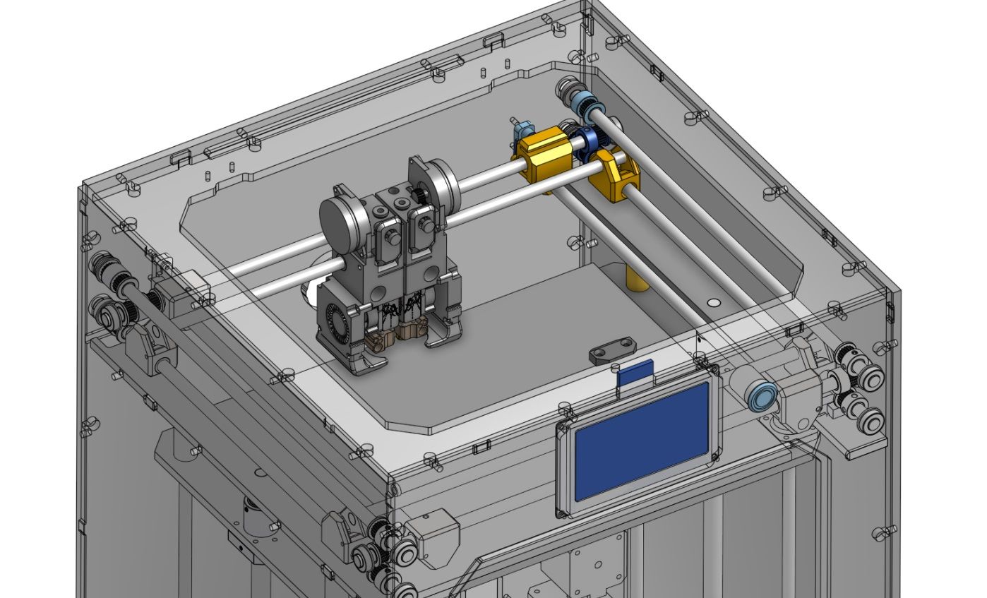
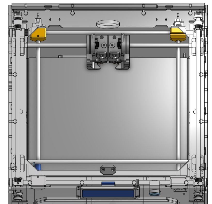
Two BMG extruders with micro motors Nema 14
Two axes X and U
Print size in the first version 220x220x300
Z Axis consists of two SFU1204
Chamber ventilation
Further heating the chamber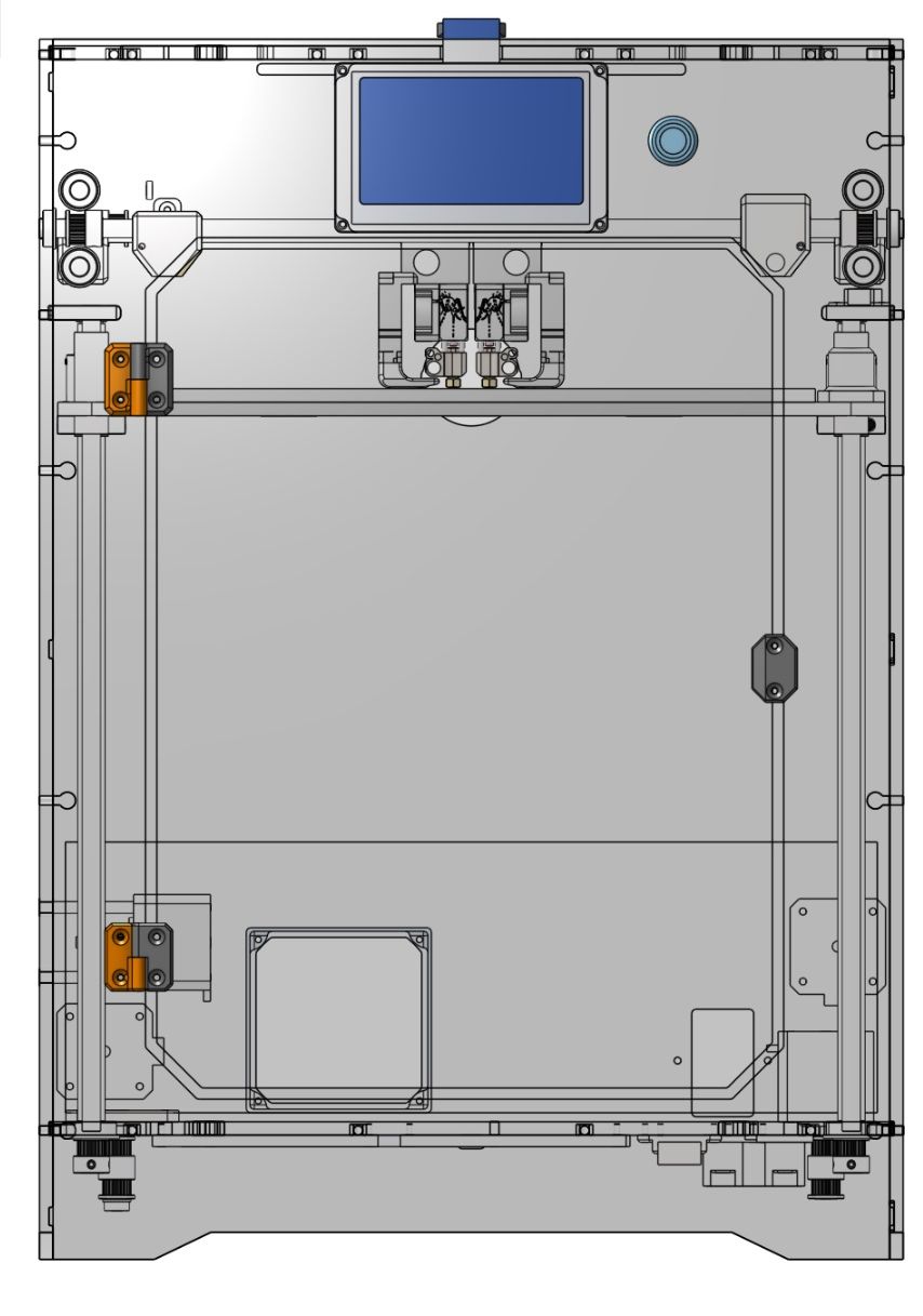


Issues known to me:
I have managed to start printing with the left extruder so far. Mirror and parallel mode does not work.
Mesh Bed Leveling
Which slicer CURA or BCN3D.
Start and end G-Code.
Airflow ( Blower) does not work.
Macros
Well, in general, my Config.g does not inspire confidence in meconfig.g
homeall.g
tpre0.g tpost3.g tpost2.g tpost1.g tpost0.g tfree3.g tfree2.g tfree1.g tfree0.g stop.g pause.g homez.g homey.g homex.g homeu.g -
; Configuration file for Duet WiFi (firmware version 3)
; executed by the firmware on start-up
;
; generated by RepRapFirmware Configuration Tool v3.1.4 on Tue Aug 25 2020 12:07:49 GMT+0200 (Mitteleuropäische Sommerzeit); Divers
M564 H0
; General preferences
m80 ; Power ON
G90 ; send absolute coordinates...
M83 ; ...but relative extruder moves
M550 P"DE-TechArt IDEX V1" ; set printer name; Network
M552 S1 ; enable network
M586 P0 S1 ; enable HTTP
M586 P1 S0 ; disable FTP
M586 P2 S0 ; disable Telnet; Drives
M569 P0 S0 ; physical drive 0
M569 P1 S1 ; physical drive 1
M569 P2 S1 ; physical drive 2
M569 P3 S1 ; physical drive 3
M569 P5 S1 ; physical drive 4
M569 P6 S1 ; physical drive 5
M584 X0 Y1:4 U3 Z2 E5:6 ; set drive mapping
M350 X16 Y16 U16 Z16 E16:16 I1 ; configure microstepping with interpolation
M92 X100 Y100 U100 Z1200 E832:832 ; Set steps per mm
M566 X620 Y620 U620 Z80 E500:500 P1 ; Set maximum instantaneous speed changes (mm/min)
M203 X12000 Y12000 U12000 Z900 E3600:3600 ; Set maximum speeds (mm/min)
M201 X1900 Y1900 U1900 Z250 E800:800 ; Set accelerations (mm/s^2)
M906 X850 Y850 U850 Z500 E300:300 I20 ; Set motor currents (mA) and motor idle factor in per cent; Axis Limits
M208 X123 Y115 U123 Z100 ; Set axis maxima
M208 S1 X-123 Y-115 U-123 Z0 ; Set axis minimum; Endstops
M574 X1 S1 P"!xstop" ; configure active-high endstop for low end on X via pin xstop
M574 Y1 S1 P"!ystop" ; configure active-high endstop for low end on Y via pin ystop
M574 U2 S1 P"!e0stop" ; configure active-high endstop for low end on U via pin ustop; Z-Probe
M558 P1 C"!^zprobe.in" H5 F120 T6000 ; Set Z probe type to inverted, unfiltered piezo and the dive height + speeds
G31 P700 X0 Y0 U0 Z-0.2
M557 X-98:98 Y-98:98 S70 ; Define mesh grid; Heaters
M308 S0 P"bedtemp" Y"thermistor" T100000 B4138 ; configure sensor 0 as thermistor on pin bedtemp
M950 H0 C"bedheat" T0 ; create bed heater output on bedheat and map it to sensor 0
M307 H0 B0 S1.00 ; disable bang-bang mode for the bed heater and set PWM limit
M140 H0 ; map heated bed to heater 0
M143 H0 S120 ; set temperature limit for heater 0 to 120CM308 S1 P"duex.e2temp" Y"thermistor" T100000 B4138 ; configure sensor 1 as thermistor on pin duex.e2temp
M950 H1 C"duex.pwm1" T1 ; create nozzle heater output on duex.pwm1 and map it to sensor 1
M307 H1 B0 S1.00 ; disable bang-bang mode for heater and set PWM limitM308 S2 P"e1temp" Y"thermistor" T100000 B4138 ; configure sensor 2 as thermistor on pin e1temp
M950 H2 C"e1heat" T2 ; create nozzle heater output on e1heat and map it to sensor 2
M307 H2 B0 S1.00 ; disable bang-bang mode for heater and set PWM limit; Fans
M950 F0 C"duex.fan8" Q500 ; create fan 0 on pin duex.fan8 and set its frequency
M106 P0 S0 H-1 C"Blower X"; set fan 0 value. Thermostatic control is turned off
M950 F1 C"duex.fan7" Q500 ; create fan 1 on pin duex.fan7 and set its frequency
M106 P1 S0 H1 T45 C"Fan X" ; set fan 1 value. Thermostatic control is turned onM950 F2 C"fan0" Q500 ; create fan 2 on pin fan0 and set its frequency
M106 P2 S0 H-1 C"Blower U"; set fan 1 value. Thermostatic control is turned off
M950 F3 C"fan1" Q500 ; create fan 3 on pin fan1 and set its frequency
M106 P3 S0 H2 T45 C"Fan U" ; set fan 3 value. Thermostatic control is turned onM950 F4 C"duex.fan5" Q500 ; create fan 4 on pin duex.fan6 and set its frequency
M106 P4 S1 H-1 C"LED" ; set fan 4 value. Thermostatic control is turned offM950 F5 C"duex.fan6" Q500 ; create fan 4 on pin duex.fan6 and set its frequency
M106 P5 S1 H-1 C"LED" ; set fan 4 value. Thermostatic control is turned off; Tools
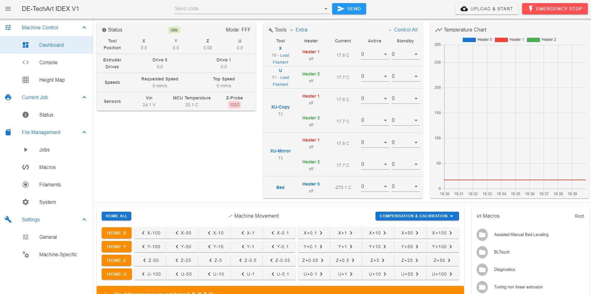
M563 P0 D0 H1 X0 F1 S"X" ; define tool X tool 0 uses extruder 1, heater 1 and fan 1
G10 P0 X0 Y0 Z0 R0 S0 ; set tool 0 axis offsetsM563 P1 D1 H2 X3 F3 S"U" ; define tool U tool 1 uses extruder 1, heater 2 and fan 3
G10 P1 Y0 U0 Z0 S0 R0 ; set tool 1 axis offsetsM563 P2 D0:1 H1:2 X0:3 F1:3 S"XU-Copy" ; define tool X+U copy mode
G10 P2 X58.75 Y0 U-58.75 S0 R0 ; set tool offsets and temperatures
M567 P2 E1:1 ; set mix ratio 100% on both extrudersM563 P3 D0:1 H1:2 X0:3 F1:3 S"XU-Mirror" ; define tool X+U mirror mode
G10 P3 X58.75 Y0 U-58.75 S0 R0 ; set tool offsets and temperatures
M567 P3 E1:1 ; set mix ratio 100% on both extruders; Miscellaneous
M501 ; load saved parameters from non-volatile memory
;T0 ; select first tool; CPU temp calibration
M912 P0 S-11; Automatic power saving
M911 S22 R23 P"M913 X0 Y0 U800 G91 M83 G1 Z3 E-1 F1000" ; Set voltage thresholds and actions to run on power loss -
; homeall.g
; called to home all axesM106 P0 S0 ; Part cooling Fan off
G91 ; relative positioningG1 H2 Z5 F6000 ; lift Z relative to current position
G1 H1 X-650 Y-550 U650 F5000 ; first pass XYU
G1 H2 X5 Y5 U-5 F6000 ; go back a few mm
G1 H1 X-20 Y-20 U20 F360 ; second pass XYG90 ; absolute positioning
G1 X0 Y0 U600 F8000 ; first bed probe point -> move X to the middle of the Bed, U outside and home ZG30
; homeu.g
; called to home the U axis
;
; generated by RepRapFirmware Configuration Tool v3.1.4 on Tue Aug 25 2020 12:07:49 GMT+0200 (Mitteleuropäische Sommerzeit)
G91 ; relative positioning
G1 H1 U215 F1800 ; move quickly to Y axis endstop and stop there (first pass)
G1 H2 U-5 F6000 ; go back a few mm
G1 H1 U215 F360 ; move slowly to Y axis endstop once more (second pass)
G90 ; absolute positioning; homex.g
; called to home the X axis
;
; generated by RepRapFirmware Configuration Tool v3.1.4 on Tue Aug 25 2020 12:07:49 GMT+0200 (Mitteleuropäische Sommerzeit)
G91 ; relative positioning
G1 H1 X-215 F1800 ; move quickly to Y axis endstop and stop there (first pass)
G1 H2 X5 F6000 ; go back a few mm
G1 H1 X-215 F360 ; move slowly to Y axis endstop once more (second pass)
G90 ; absolute positioning
homex.g; homey.g
; called to home the Y axis
;
; generated by RepRapFirmware Configuration Tool v3.1.4 on Tue Aug 25 2020 12:07:49 GMT+0200 (Mitteleuropäische Sommerzeit)
G91 ; relative positioning
G1 H1 Y-215 F1800 ; move quickly to Y axis endstop and stop there (first pass)
G1 H2 Y5 F6000 ; go back a few mm
G1 H1 Y-215 F360 ; move slowly to Y axis endstop once more (second pass)
G90 ; absolute positioning
homey.g; homez.g
; called to home the Z axis
;G91 ; relative positioning
G1 H2 Z5 F6000 ; lift Z relative to current position
G1 X20 Y20 U0 F800 H2 ; lift Z relative to current position
G1 H1 Z-400 F400 ; move Z DOWN until the endstop is triggered
G92 Z0 ; set Z position to axis minimum (you may want to adjust this)
homez.g; pause.g
; called when a print from SD card is paused
;M83 ; relative extrusion
G1 E-2 F3600 ; retract 2mm
G91 ; relative movement
G1 Z2 F500 ; raise head 2mm
G90 ; absolute movement
G1 H1 X-200 U200 F6000 ; park both heads
pause.g; tfree0.g
;G28 X U ; home the X and U carriages
M83 ; relative extruder movement
G1 E0 F3600 ; retract 2mm
M106 S0 ; turn off our print cooling fan
G91 ; relative axis movement
G1 Z3 F500 ; up 3mm
G90 ; absolute axis movement
G1 S2 X0 F6000 ; park the X carriage at -48mm;tfree1.g:
;G28 X U ; home the X and U carriages
M83 ; relative extruder movement
G1 E0 F3600 ; retract 2mm
M106 S0 ; turn off our print cooling fan
G91 ; relative axis movement
G1 Z3 F500 ; up 3mm
G90 ; absolute axis movement
G1 S2 U0 F6000 ; park the U carriage at +248mm;tfree2.g:
M83 ; relative extruder movement
G1 E0 F3600 ; retract 2mm
M106 S0 ; turn off our print cooling fan
G91 ; relative axis movement
G1 Z3 F500 ; up 3mm
G90 ; absolute axis movement
G28 X U ; home the X and U carriages;tfree3.g:
M83 ; relative extruder movement
G1 E0 F3600 ; retract 2mm
M106 S0 ; turn off our print cooling fan
G91 ; relative axis movement
G1 Z3 F500 ; up 3mm
G90 ; absolute axis movement
G28 X U ; home the X and U carriages
M579 U1; tpost0.g
M106 R2 ; restore print cooling fan speed
M116 P0 ; wait for tool 0 heaters to reach operating temperature
M83 ; relative extruder movement
G1 E2 F3600 ; extrude 2mm;tpost1.g:
M106 R2 ; restore print cooling fan speed
M116 P1 ; wait for tool 1 heaters to reach operating temperature
M83 ; relative extruder movement
G1 E2 F3600 ; extrude 2mm;tpost2.g:
M106 R2 ; restore print cooling fan speed
M116 P2 ; wait for tool 2 heaters to reach operating temperature
M83 ; relative extruder movement
M567 P2 E1:1 ; set tool mix ratio
M568 P2 S1 ; turn on mixing
G1 E2 F3600 ; extrude 2mm from both extruders;tpost3.g:
M106 R2 ; restore print cooling fan speed
M116 P2 ; wait for tool 2 heaters to reach operating temperature
M83 ; relative extruder movement
M567 P2 E1:1 ; set tool mix ratio
M568 P2 S1 ; turn on mixing
G1 E2 F3600 ; extrude 2mm from both extruders
M579 U-1; bed.g
; called to perform automatic bed compensation via G32
;
; generated by RepRapFirmware Configuration Tool v3.1.3 on Fri Jun 19 2020 21:08:48 GMT+0200 (Mitteleuropäische Sommerzeit)M561 ; clear any bed transform
G28
G29 ; probe the bed and enable compensation -
M584 X0 Y1:4 U3 Z2 E5:6 ; set drive mappingWhy Y1:4? Two Y axis motors? Or no? (M569 you defined 6 motors).
; Endstops
M574 X1 S1 P"!xstop" ; configure active-high endstop for low end on X via pin xstop
M574 Y1 S1 P"!ystop" ; configure active-high endstop for low end on Y via pin ystop
M574 U2 S1 P"!e0stop" ; configure active-high endstop for low end on U via pin ustop

; Z-Probe
M558 P1 C"!^zprobe.in" H5 F120 T6000 ; Set Z probe type to inverted, unfiltered piezo and the dive height + speeds
G31 P700 X0 Y0 U0 Z-0.2
M557 X-98:98 Y-98:98 S70 ; Define mesh grid
Do you need a M574 for the Z-Probe? I think yes but double check. Right now Z-probe endstop configuration (M574) is undefined.
M557 - S70 seems large compared to the bounds (098 to 98)? Can you do, say, M557 X-100:100 Y-100:100 S20? S70 is unusual
To use Mirror or Copy, your print file GCODE must select T2 or T3. You can use standard Cura, slice the file, and then replace all instances of Cura-created T0, (or even T1) with T2 or T3 so long as you take care in where you slice the object on the build plate. This is still tricky.
Do not use BCN3D Cura for Mirror/duplication mode (copy, etc) as BCN3D uses a custom version of Marlin. In their mirror/copy GCODE files, they send a custom GCODE command to tell the machine to mirror or copy. They also modify the area you can place models in their Cura software to ensure the machine does not crash.
I recommend solving one problem at a time.
First solve Bed leveling
Then solve Blower fans (these are the part cooling fans, not the heatsink fans correct?) -
@sebkritikel Thanks for the answer.
I really forgot to point out. I have one motor for each axle.
I read somewhere on the site that if I create an additional X axis, then I must also create a Y axis. maybe I was wrong.
Possibly the Z axis positioning sensor is incorrectly set but it works.
the bed rises up hits the extruder and falls down so we get point 0. I would also like to have the sensor check the entire bed for evenness.
You're right, the radiator blower is working properly.
blower fan printed parts does not start -
I also forgot to say that I decided to use positioning in the center of the bed -
@DE-TechArt said in Creating a new IDEX 3D Printer with Duet 2 WIFI:
I read somewhere on the site that if I create an additional X axis, then I must also create a Y axis. maybe I was wrong
No, you don't need to create an additional Y axis, unless you actually have two Y axes. A standard IDEX has one Y axis and two X axes. The second X axis in RRF is normally called the U axis.
Duet WiFi hardware designer and firmware engineer
Please do not ask me for Duet support via PM or email, use the forum
http://www.escher3d.com, https://miscsolutions.wordpress.com -
@DE-TechArt said in Creating a new IDEX 3D Printer with Duet 2 WIFI:
; homeall.g
; called to home all axesM106 P0 S0 ; Part cooling Fan off
G91 ; relative positioningG1 H2 Z5 F6000 ; lift Z relative to current position
G1 H1 X-650 Y-550 U650 F5000 ; first pass XYU
G1 H2 X5 Y5 U-5 F6000 ; go back a few mm
G1 H1 X-20 Y-20 U20 F360 ; second pass XYG90 ; absolute positioning
G1 X0 Y0 U600 F8000 ; first bed probe point -> move X to the middle of the Bed, U outside and home ZG30
; homez.g
; called to home the Z axis
;G91 ; relative positioning
G1 H2 Z5 F6000 ; lift Z relative to current position
G1 X20 Y20 U0 F800 H2 ; lift Z relative to current position
G1 H1 Z-400 F400 ; move Z DOWN until the endstop is triggered
G92 Z0 ; set Z position to axis minimum (you may want to adjust this)
homez.g; bed.g
; called to perform automatic bed compensation via G32
;
; generated by RepRapFirmware Configuration Tool v3.1.3 on Fri Jun 19 2020 21:08:48 GMT+0200 (Mitteleuropäische Sommerzeit)M561 ; clear any bed transform
G28
G29 ; probe the bed and enable compensationYour bed.g looks fine, however at the end of my homeall.g and homez.g I have "G29 S1" to load my heightmap.
Have you been able to run a full bed probing? G29? I think you need to change your M557, as you have your bounds set to a 196mm length for each axis, divided by 70mm spacing..... Or try -95 to 95, with a spacing of 19mm (S19). 70mm is too large I think, especially for your bed size, to give a good bed leveling result, excluding the fact it does not divide nicely into 196.
-
Hey. I'm new to 3D printers. but I want to create my own. body and kinimatics are. Can you help me set up the control board?
-
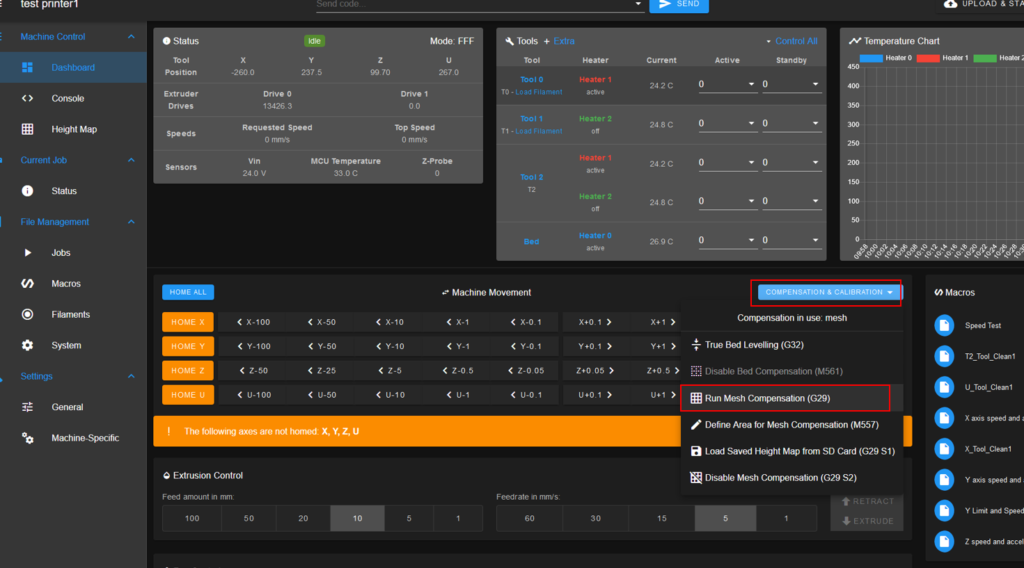
@sebkritikel No, I was unable to run a full bed probing. I don't quite understand how I can run this. for a start, I think that four points will be enough -95 and 95
-
@sergei I think on my example you and others can create your own project.
-
@DE-TechArt said in Creating a new IDEX 3D Printer with Duet 2 WIFI:
@sebkritikel No, I was unable to run a full bed probing. I don't quite understand how I can run this. for a start, I think that four points will be enough -95 and 95
I think you will want a greater fidelity... but lets start with something that divides nicely into your bounds... For reference, on my IDEX machine I have "M557 X-220:160 Y-200:200 S20:25 ; define mesh grid" and many other times you will see folks with spacing of 20-25mm.
https://duet3d.dozuki.com/Wiki/Using_mesh_bed_compensation
Simply put - what happens when you type and send G29 in the console? Can also click here:
Have you corrected the additional Y-axis comments DC42 brought up? You have your X-axis, which is the T0 (left I assume) hotend. You have the U-axis, which is the T1 (right I assume) hotend. You have one Y-axis - that is driven by only one motor correct? Should be "M584 X0 Y1 U3 Z2 E5:6 ; set drive mapping " correct?
Happy to help!
-
@sebkritikel Thank you for the tips. as I said, without your help I cannot cope.
G31 P700 X0 Y0 U0 Z0
M557 X-98:98 Y-98:98 S20:25 ; Define mesh grid
I changed the G-code and now the mesh bed probes are working. all that remains is to adjust the speed and acceleration.The next problem is getting the printer to work in parallel and mirrored.
it is not clear to me where in cura should I indicate T1 T2 and T3?
Just in the starter G-Code? I think it's not very convenient to edit the parameters of the 3d printer every time -
I also changed set drive mapping
M584 X0 Y1 U3 Z2 E5:6 ;and added at the end Homeall.g and homez.g
G29 S1 -
@DE-TechArt said in Creating a new IDEX 3D Printer with Duet 2 WIFI:
@sebkritikel Thank you for the tips. as I said, without your help I cannot cope.
G31 P700 X0 Y0 U0 Z0
M557 X-98:98 Y-98:98 S20:25 ; Define mesh grid
I changed the G-code and now the mesh bed probes are working. all that remains is to adjust the speed and acceleration.The next problem is getting the printer to work in parallel and mirrored.
it is not clear to me where in cura should I indicate T1 T2 and T3?
Just in the starter G-Code? I think it's not very convenient to edit the parameters of the 3d printer every timeFor standard dual extrusion, this is how I use Cura
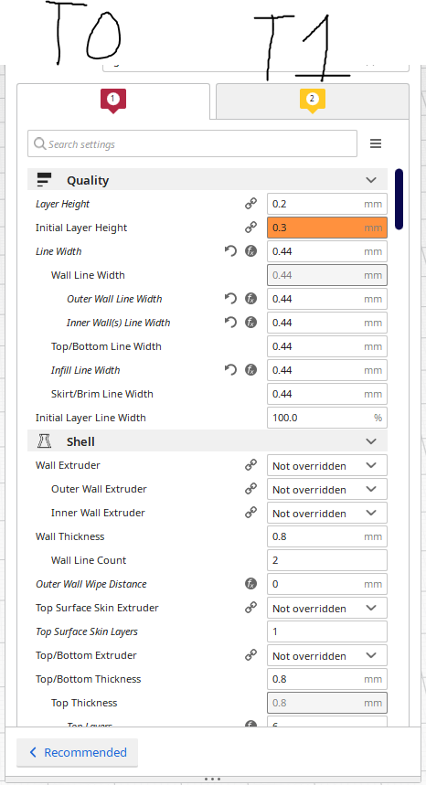
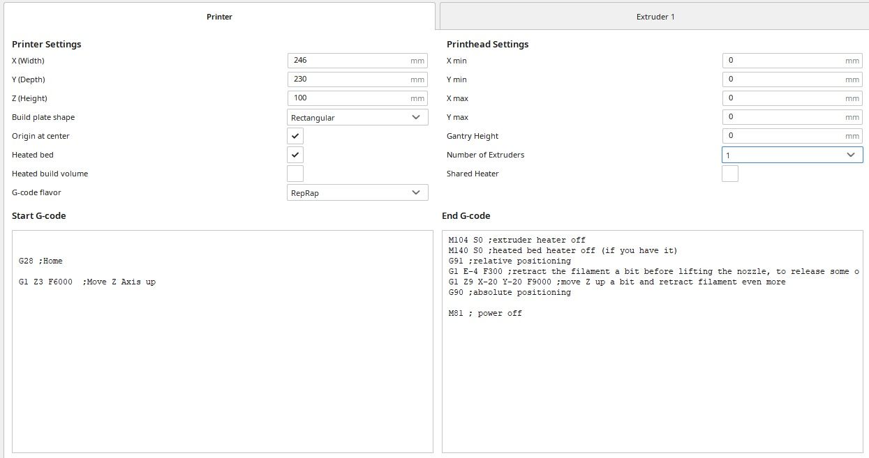
The start GCODE is very important for me. Cura is not a perfect software, and has some quirks. Before the start GCODE, Cura actually calls the tool for the start of the print, see below - T0 is called before my start script
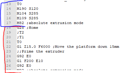
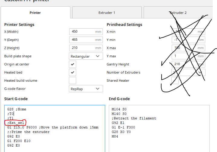
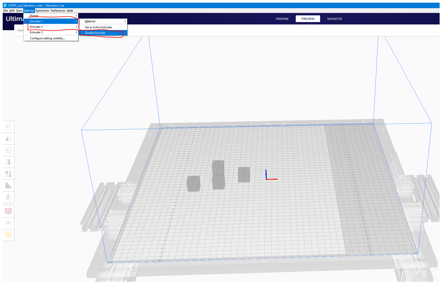
In my homeall.g, I actually need to deselect the current tool using T-1 P0, otherwise if I'm printing with T1, T2, etc, Cura tricks my machine into trying to Z probe with the wrong tool(s). I added the ;Ext_Sel line into my start GCODE, and then use the Post Processing Plugin to manually select the proper starting tool.
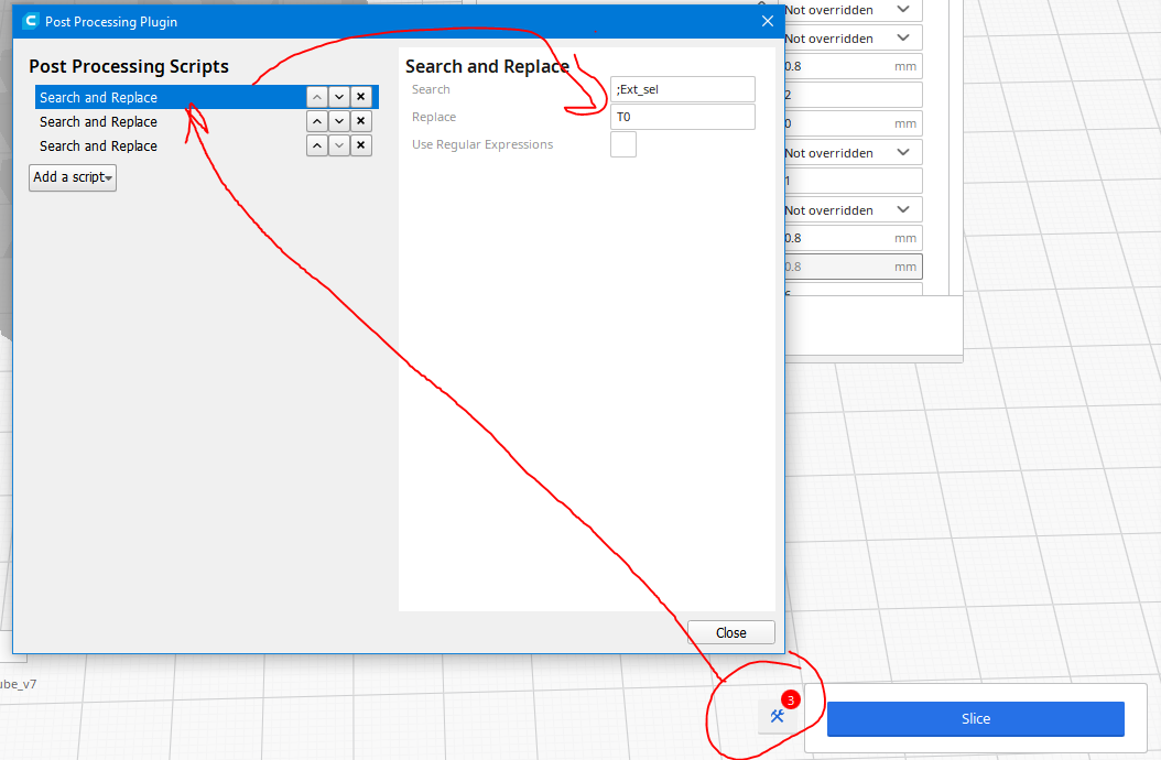
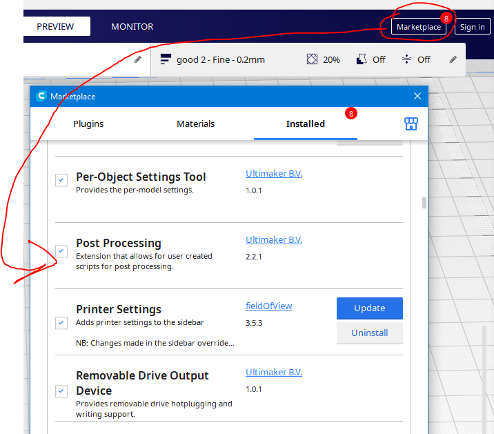
For specifically duplication and mirror modes, I have a SECOND post processing script to change all mentions of T0 or T1 to T2. This one is silly, but I do it instead of creating another tool/extruder in Cura. I slice it for T0 (typically), do my first search and replace script to change ;Ext_Sel to T2 (to specify the tool after my G28 in start GCODE), and then a second search and replace script to change T0 anywhere else to T2 (specifically the FIRST tool mention created by Cura before the start gcode is made, the section in blue from the notepad file a few pictures up).
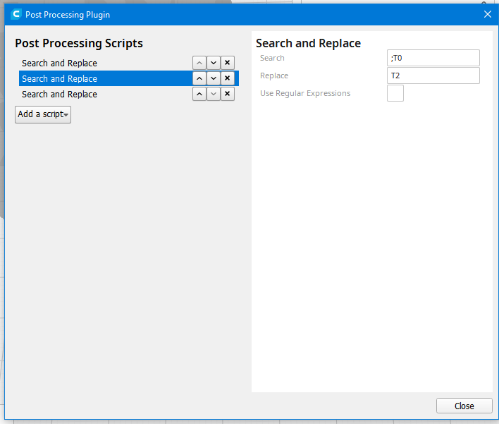
If not using T2, it must say ";T2" instead of "T2" - or T3 for mirror, etc.I think there are better ways of doing some of that... unfortunately the Duet board and firmware is much smarter and more configurable than Cura....
-
I think a better option is to create a third "extruder" in Cura through the "Machine Settings" window, and selecting a sufficient X or Y nozzle offset to split the bed in half or so, leaving space for the Duet firmware to map the movement to the U-axis.
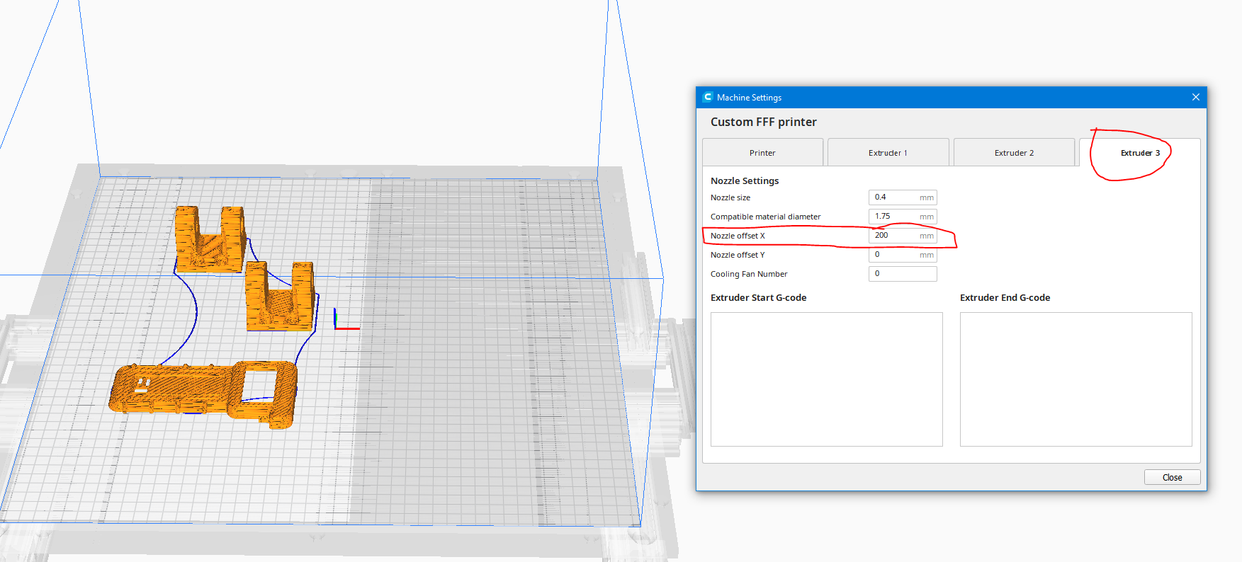
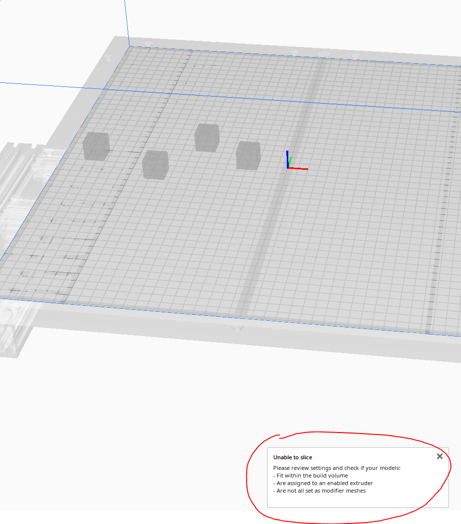
I have not tried this yet, but I think this would be much easier. An important note - my T2 offset is different than yours, I did not offset the X axis, and instead only offset the U axis. This suggestion with Cura might not work with how you have offset the X and U axis - more investigation needed.M563 P2 D0:1 H1:2 X0:3 ; tool 2 uses both extruders and hot end heaters, maps X to both X and U G10 P2 X0 Y0 U-263.5 S0 R0 ; set tool offsets and temperatures for tool 2Strike that, I hadn't actually selected T2 (Extruder 3) as the print tool. By adding Extruder 3 it split the buildplate for T0/T1, not just T2. When you select T2, it actually makes the entire print surface unusable - wtf Cura.
-
Getting closer, but still not quite right. Some funky stuff going on in the background w/Cura.
With "Origin at Center" the previously entered X offset applies starting at the origin... but only if tools T0 and T1 (extruder 1 and 2 in cura) are disabled. Whatever you enter - such as 100mm, is for only one direction, therefore the overall width would be 2x (200 mm for example).
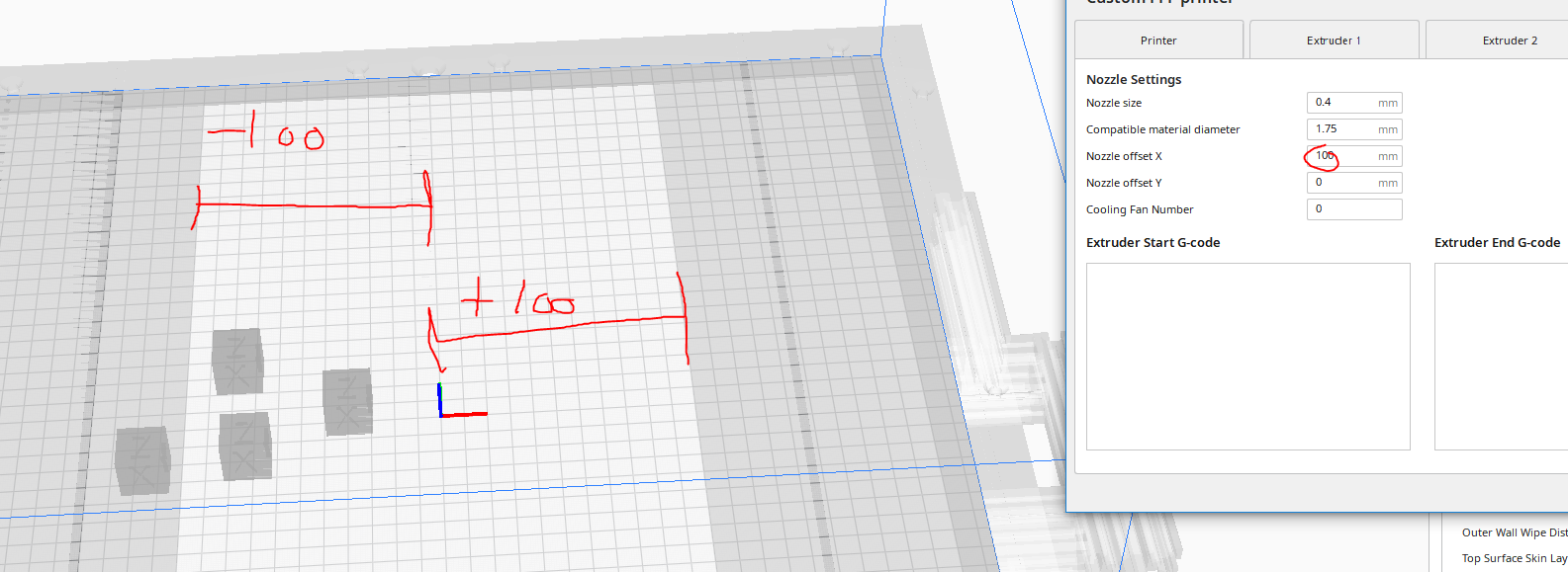
However, any combination of having T0, T1 active, with T2 both active as well disabled, results in the right hand side available build surface being truncated by whatever the X offset is set to (loss of 100mm. If the offset was -100mm, it happens to the left side of the bed, as expected). I don't understand the reasoning why... If T2 is disabled, why is the offset being applied? Is Cura really assuming that T2 will always travel during printing (a single gantry/print head), and thus must limit that offset amount? I think that is shortsighted... but perhaps the alternative is as well. I just tried expanding the machine X total print width from 450mm to 650mm in Cura (double the X offset in T2) which solves the T0, T1, T2 combo issue, but then that totally messes up the T2 only print area. Stumped for now........
-
@sebkritikel This is a rather complicated method. I do not think that a beginner and an ordinary consumer can handle it.
And why are you against bcn3d Cura? it was designed specifically for IDEX printer -
@dc42 the developers of Duer3D and RepRap were able to create such complex software and nevertheless do not have detailed instructions for setting up an IDEX printer, the process of slicing, extruder selection, initial and final GCode, Slicer selection and much more are not described. Perhaps I missed something and such an instance exists?
-
@dc42 I also have one question. I am going to use Duet equipment in my invention and further replicate it, can I get support from the software developers in my printer settings?