Extrusion Calibration?
-
You are the first person who as calibrated their x , y.
The way to find out if you have X , Y error and not under / over extrusion is make a stepped cube.
if you make a cube 50mm squared and it is 50.2mm , what is the problem ? , but if you make a second cube at 100mm squared and it is 100.2mm it is not X and Y -
You are the first person who as calibrated their x , y.
I'm sure that I'm not the first person. A buddy gave me that "tip".
")
if you make a cube 50mm squared and it is 50.2mm , what is the problem ? , but if you make a second cube at 100mm squared and it is 100.2mm it is not X and Y
I got your point and I fully agree. I was running into the wron direction here.
I made a 20mm and a 60mm cube.
20mm: X=20,20 Y=20,20
60mm: X=60,20 Y=60,20I can hear your: "Toult you so" till here to my desk.
The values for z are missing here, That is a other story and I'm not able to get the cube off the bed at the moment. (3DLAC have it's downsides.
)I will do some more extrusion tests later or tomorrow.
Cheers, Chriss
-
@Chriss said in Extrusion Calibration?:
That is a other story and I'm not able to get the cube off the bed at the moment. (3DLAC have it's downsides. )
Yep I use 3DLAC for them times you just can't get it to stick or you really don't want a small part to come loose.
I try not to use it on PLA unless I have to , but PETG is a must or you will crack the glass.What is your bed temperature ? and what is your bed temperature when you are trying to remove your part ?.
I've found that there is no part trying to remove your part if the bed is above 30c , but if you heat the bed to 60c it will remove it's self or with a slit knock at about 25-28c.
With PETG and 80c bed you know when that is ready you hear a very loud crack, if you are using something like 3DLAC that is your part removed if not it is your bed glass cracked. -
@peter247 said in Extrusion Calibration?:
@Chriss said in Extrusion Calibration?:
That is a other story and I'm not able to get the cube off the bed at the moment. (3DLAC have it's downsides. )
Yep I use 3DLAC for them times you just can't get it to stick or you really don't want a small part to come loose.
I try not to use it on PLA unless I have to , but PETG is a must or you will crack the glass.I use the 3DLAC since I switched from PEI to Pertinax. I was not able to get big prints to stick on the bed. That was a bad decision, the next surface will be PEI again.
What is your bed temperature ? and what is your bed temperature when you are trying to remove your part ?.
I print PLA with 60°C and usually I wait till it is back to room temperature, well smaller parts get off if the bed is still warm.
I've found that there is no part trying to remove your part if the bed is above 30c , but if you heat the bed to 60c it will remove it's self or with a slit knock at about 25-28c.
I which that a slit knock would be enough. I sharpened the front of my spattle to slight better under the object.
With PETG and 80c bed you know when that is ready you hear a very loud crack, if you are using something like 3DLAC that is your part removed if not it is your bed glass cracked.
") I wish that this could happen with PLA.
I wish that this could happen with PLA. Well, I dialed in my z-offset today, for the nozzle change. I had to lift it 0.1mm, so the Elephant foot has gone now and the smaller cube was easy to remove now. I think that this will be the case with bigger object, too.
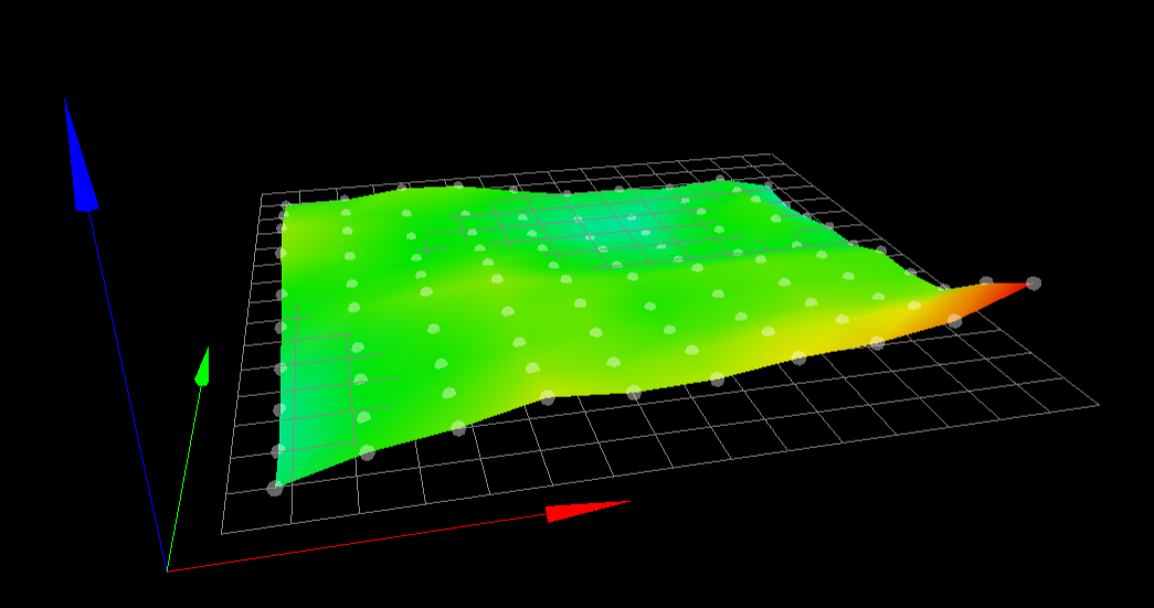
I printed a first layer which covered the complete bed. And I saw the ruff first layer appearing at the "max Y - min Y" corner:

Is that caused by an uneven bed? I saw that in the mast from time to time on my PEI sheet, too and I was not able to find the reason for it.
Cheers, Chriss
-
Does your printer have auto / mash bed levelling and does it have a bltouch or micro switches for Z height ?
Do you own a pair of digital callipers ?
How do you levelling your bed ?
It is hard to get scale on the print how big is it ?
Looking at your print the first layer looks like it is thicker in parts of the print by the edges.
To me it looks like it is under extruding .Ender 5 plus linear rail and hemera powered by duet 2 wifi , CR10s pro v1 with bltouch mostly stock , BLV mgn Cube slowly being built powered by duet 3 mini 5+
-
Can you get a better photo?
-
@peter247 said in Extrusion Calibration?:
Does your printer have auto / mash bed levelling and does it have a bltouch or micro switches for Z height ?
There is a BLTouch in place.
Do you own a pair of digital callipers ?
At least 10, but most of them are analog, I hate the battery changing drill. I used a micrometer screw to measure the thickness: The numbers in circles are the number of the stripe, the other numbers are the thickness at this place. The order of 4 and 5 are wrong.


How do you levelling your bed ?
What do you want to read?
homez.g:M300 S500 P1000 ; Beep G90 G1 Y155 X155 F6000 ; go to first probe point M400 G91 ; relative positioning ; Run 1 M558 F250 ; Chriss - set the down speed G30 ; Run 2 M558 F60 ; Chriss - set the down speed G30 M558 F350 ; Change the speed backThe mesh:
M557 X10:270 Y40:270 P10:10Zlevel:
G30 P0 X0 Y155 Z-99999; probe near a leadscrew, half way along Y
G30 P1 X250 Y155 Z-99999 S2 ;
Hightmap:
I used a feeler gauge at every screw in the corners to level the bed mechanically.
It is hard to get scale on the print how big is it ?
20x35mm ruffly
Looking at your print the first layer looks like it is thicker in parts of the print by the edges.
To me it looks like it is under extruding .I think that the the z offset is wrong. The first layer should have 0.20 from the slicer, but it is more in average over the complete bed. That is a bit strange. I will tune in the z-offset again and print the first layer one more time.
Some more pictures:


Back site:

@Phaedrux Are they good enough?
Cheers, Chriss
-
@Chriss said in Extrusion Calibration?:
@Phaedrux Are they good enough?
Yes. Confirms that it looks like the nozzle is too close in those areas.
The image of your heightmap shows a bit of tilt front to back, raised in the front. I think you could probably level the bed a bit better.
-
Thanks...
Let me repeat it: The roughness comes from over extrusion because the gab between the nozzle and the bed is to narrow.
I will re level the bed and will print tiny batches of first layers. Lets see how they look than.
Cheers, Chriss
-
bedlevel_nozzle_0.4_200x200-0.3-0.8.stl
Here's a good quick bed level test print to verify mesh compensation is working well. Print once with it disabled and once with it enabled.
-
Yes, I will. I will make sure that the mechanical part will do it's job too.
-
The HightMap looks like that now:
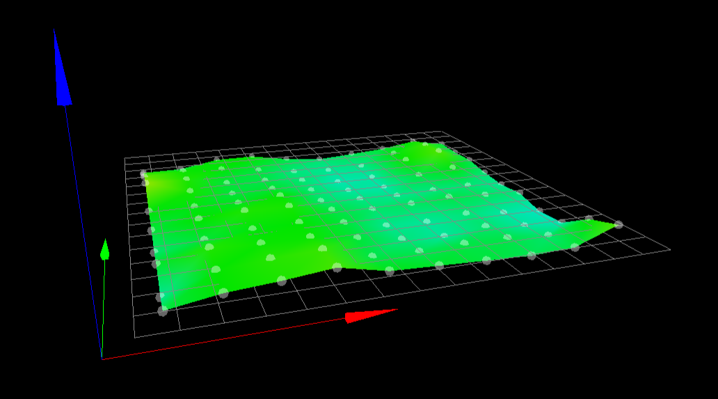
Very much the same warping which is not an surprise. The front right corner is a bit smoother now.
-
I have printed the "leveling_test" files. Once "normal" with the mesh compensation and once without it (G29 S2). I touched the lead screws from time to time so I was able to feel that the motors where rotating while the head was traveling when the mesh compensation was enabled. They did not rotate while the mesh compensation was off.
With:

Without:

I have some more pictures, but I do not want to spam here.
The squares on the bed to look very good stick on the bed. I will print the big one again, lets see how that ends up now.
Cheers, Chriss
-
What is your printer a know type like a cr10 ?.
Have you tried printing on glass or a mirror ? -
It is a cr10 pro v2.
No, I tried PEI, Pertinax, FR4 and I have a sheet of printbite on my RatRig CoreXY. But this one is still "under construction". I had no chance to tune it in toll now. The CR10 have still to much problems.I'm not sure whether I want to try glas or not. I heard about enough problems there, too. And I think that the trend goes away of it, too.
Cheers, Chriss
-
Yes , another cr10s pro owner !!!!
Mine is a cr10s pro v1 , but with the bltouch upgrade .Now I know your machine a little better , how is the gantry on Z is it level and is the uprights level.
Mine was a pig at first I had to take to gantry apart to get the z axis to run level.
Just a personal one !!!! did you fit the duet in the control box.I use one of these :-
-
The portal was not optimal square and it was slightly bent to the back. I fixed that with some slices metal out of a beer can.
But I would not bet that it is perfect now.I printed a "holder", which are basically for "pins" on a rectangle:
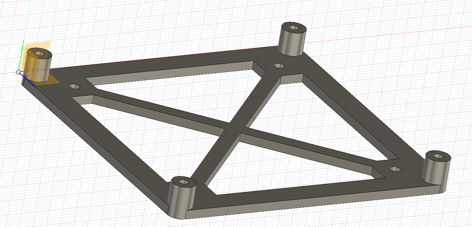
I glued it right to the original mainboard and the expansion board to the place where the original mainboard was. That works very well.
I do not need access to the USB and micro SD card, so that is no problem for me, I'm happy with the network access. I swapped to many floppies, harddisks, SD-Cards in my live, I'm more than happy that I do not have to do that any more.Hahaha... I ordered the same product a minute ago while you edited your post.
Cheers, Chriss
-
Didn't the cr10s pro v2 come with one of these ?.
https://technologyoutlet.co.uk/collections/printer-parts-spares/products/carborundum-glass-plate?variant=32606698438735Or was it like the v1 a metal plate with a buildtakie clone sheet ?
Ender 5 plus linear rail and hemera powered by duet 2 wifi , CR10s pro v1 with bltouch mostly stock , BLV mgn Cube slowly being built powered by duet 3 mini 5+
-
I'm not sure whether it is getting better or not:


I will cut it again later and measure it again. I need to spend some attention to the paperwork for my accountant.
Cheers, Chriss
-
@peter247 said in Extrusion Calibration?:
Or was it like the v1 a metal plate with a buildtakie clone sheet ?
It came with that plastic thingy glued on a alu plate, I guess to reach the same high as the carborundum plate. I tried to get that some month ago but I was not to get one of them. There where so hard soled out that even Creality in CN canceled my order after some month.
I ordered on from Amazon and I ordered a similar one from one of my preferred dealers here in Germany:
https://www.3djake.de/3djake/glasplatte-mit-chem-beschichtungIt seams to me that this is very much the same coating.
Btw: I replaced the original heater and the metal plate with a fine routed 4mm aluminum plate. The original one was to close to a banana for me. And I wanted to switch to a 240V heater anyway.
Cheers, Chriss