Printed parts deformed
-
I printed the test and itis a lot deformed
 There are about 4mm difference in a 250mm wide model. Diagonals are 35.5mm vs 35.1 mm
Didn't notice that before.
Looking at the belt I discovered that on the left side the belt doesn't go straight during all the movement of the carriage from left to right.
The problem appear between G and F arm of the belt It go from up to down in the P2 pulley.Here is a video
https://youtu.be/xshAWXCeoco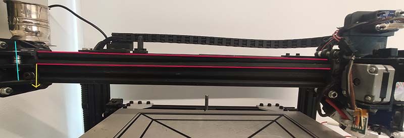
It seems to me that the axis of the pulley ( light blue in the photo) is not perfectly vertical so the belt ( red) running on it tend to go down. On the other side of the machine the belts are parallel
This is the test result
Can you suggest to me where to start for trying to fix it?
Thank you
-
regarding the video
that means that there is an angle somewhere.
either in the idler mounting or the belt mounting itself.
your belt also looks damaged
also check that each corner is exactly 90 degrees.
from the photo you x axis looks like its at an angle.
-
Thank you for your analysis.
I already ordered a new belt, and I am going to check the 90 degrees of the axis.
The printed test part isn't it is original orientation. I am going to print another one to try to understand where the distortion starts. -
You may want to go back through the XY motion platform build process to ensure it's all square and even.
The belt definitely looks damaged, and it looks like it was damaged by running on the flange of the bearing, so I think it is a result of the unintended angle rather than the cause of it.
Are your printed parts in use on the printer itself also malformed?
-
The printed part come from another printer and seems ok.
I am rechecking all the structure but I am missing something .
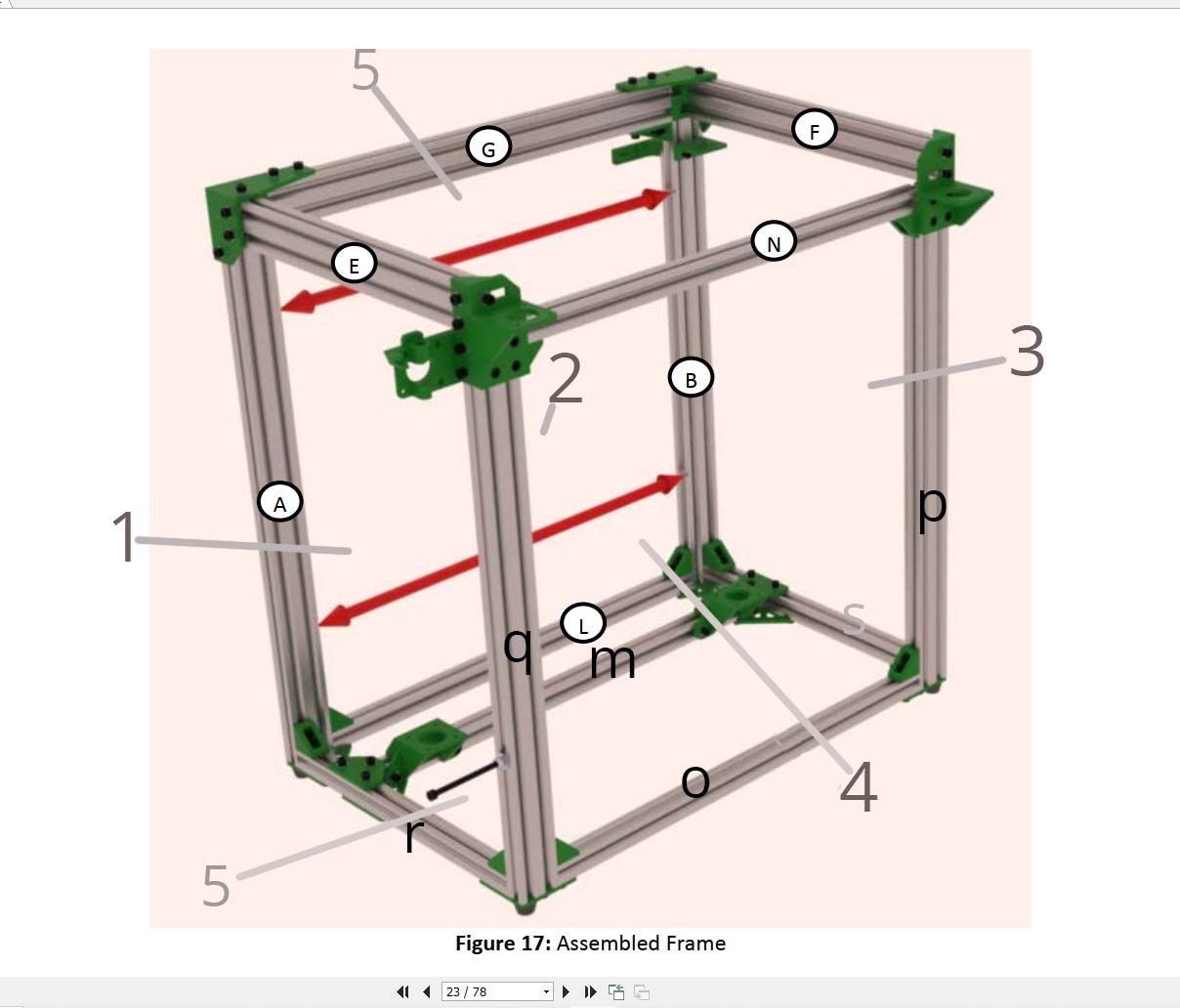
I'll try to explain my situation.Assuming the d-bot is a dice it have 6 faces each one delimitated by 4 vslot peaces
1 left ( AEQR)
2 back (AGBL)
3 right (BFPS)
4 front (NPOQ)
5 bottom (RLSO)
6 top (GFNE)I measured the distance between the vertical parts of the frame
A-Q
A-B
B-P
P-Q
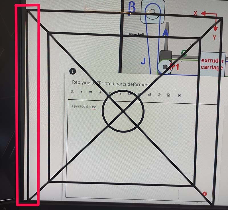
All are the same so they should be parallelI measured the diagonal on the top ( face 5) here I have a small differences of about 1.5mm between the 2
But when I measure with a 90-degree square the angle EG and GF thera arent at 90 degrees with a maximum difference of about 0.75 degrees that produce a difference of about 2mm at the and of the square.
I don't know if this is somehow clear
")
From where I can start solving this?
-
-
Thank you for your help.
My situation is this .This is face 5 ( x/y top plane). I can't understand best way to fix this.
-
@claustro
like phaedrux told you. your frame does not have 90 degree angles. -
I am missing something.
Phaedrux told me to square EG and EF so if I understand correctly he is holding me that the angle between EG and EF must be 90 isn't it?
I measured the distance between EF and NG and it is constant at every point.
So I am assuming it EF and EG are parallels.
This is true for all the part of my frame
so AB, BP,PQ,QA.
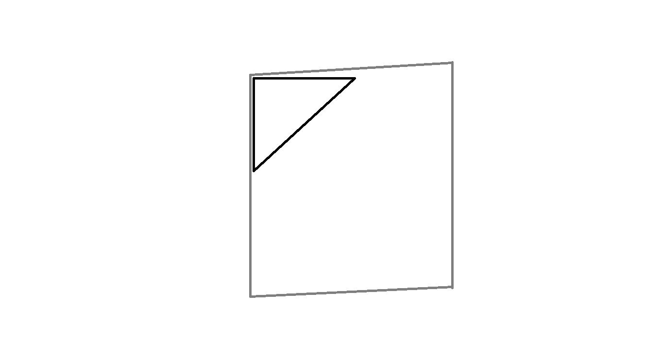
So I thought that the problem is that my frame is skewed as I sketch in my post above.I really cant' understand why the frame don't have to be at 90 degree
Can you tell me a practical process for "square " EG and EF other than measuring distances if the angle isn't the problem?
-
@claustro as the other said, your frame is not square looking from the top. This means your x and y axes won't be perpendicular and you will get skewed prints (note that your drawing above looks very much like what you're print looks like!)
You need to get the angles to as close to 90deg on your frame as possible. So start loosening the bolts, reposition the frame extrusions and get all those angles to 90deg. Keep measuring as you tighten it back up. To me, it looks like your member E has pivoted a small amount on the corner piece to G (E is only held by one screw there so will have some freedom to move before tightening).
If you can't the frame square, you might need to consider reprinting the corner pieces (as they maybe skewed), or trying to file them down etc, as they may be pushing the corners out
This is one of the most annoying things to get right on a printer - took me many attempts to get mine right...
E3D TC with D3Mini and Toolboards.
Home-built CoreXY, Duet Wifi, Chimera direct drive, 2x BMG, 300x300x300 build volume
i3 clone with a bunch of mods -
@claustro said in Printed parts deformed:
I measured the distance between EF and NG and it is constant at every point.
have you heard of a parallelogram? EF and NG constant distance is true for a parallelogram.
and what you are printing is also called a parallelogram.
-
@Veti Yes I know what a parallelogram is I understand what my problem is but I misread your post as " your frame does not have TO HAVE 90 degree angles" so this was
confusing me -
@engikeneer thank you very much for your input . I think I discovered the problem in a far from perfect printed angle.
I gonna try to check every angle I let you know -
Thank you all for your help. I managed to solve the problem ...but not as expected:-)
I reprinted main frame parts. disassembled all the printer and reassembled as perfectly as I can. Changed the belts
Then I printed the test part and it come out exactly as the previous one!!
At first, I thought about an error in the stl so I designed another one by my self but also this one come out skewed.
Then a flash in mi mind! how a can a part come exactly skewed ass the previous one even after building and rebuilding the printer? I checked the configuration file and the m92 was
M92 X101 Y100 Z1000 !!!!
Maybe changing stuff in config I mistyped a 1 and so the problem suddenly appeared!
M92 X100 Y100 Z1000 and now print a 300x300 square with diagonals in 0.5mm tolerance. -
well there is a guide on how to ask for help
https://forum.duet3d.com/topic/5909/guide-for-posting-requests-for-help
and it says to include as much information as possible.
if you had posted that i am sure someone would have immediately picked up on that.are you sure that Z1000 is correct. that is a very unusual number
-
@Veti My post wasn't a critique for someone. It was just a follow up of my story
")
-
@claustro
i know, its just hard to get users to post the relevant information.
it would make it easier most of the time -
@Veti In this case it would difficult for me to add more information than what I provided because I didn't know my config file could be involved. The last time I edited it, excluding z offset was many weeks ago, but I didn't notice the defect before, maybe because lastly I printed many "organic" parts
Also, the broken belt drift my attention to a hardware problem, I never thought about a configuration problem till all other causes was canceled
Anyway, my printer is now more squared -
Glad you figured it out. That could have been very hard to catch for a long time.
It's a good example of going over all the basics to double check.