Stepper precision +-5%
-
This post is deleted! -
@JoergS5
Found that for a "printed" angle-gauge:
https://reprapltd.com/3d-printed-angle-gauge/
-> it is really cool to generate a template https://www.blocklayer.com/protractor-print.aspx for a copy-shop for a big plot -
@mendenmh said in Stepper precision +-5%:
The spacing of microsteps is also very load dependent. Under no load, it is roughly uniform, but because the magnetic interaction is strongest when you are on a full step (where the metal poles exactly align), the partial steps are much springier, and more load dependent, than the full steps. That is one of the reasons people like to make layer heights on 3d printers a multiple of full steps. Using anything else can result in moiré patterns on the layering axis.
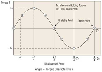
@mendenmh, do you have a model for how the spring 'constant' varies with partial step positions? I've been assuming a roughly sinusoidal displacement/torque curve (as the figure below), modeling the region close to the stable point as a linear spring. I'd like to understand how much the slope of that region varies with the sub-step position.
-
@LB said in Stepper precision +-5%:
@JoergS5
Found that for a "printed" angle-gauge:
https://reprapltd.com/3d-printed-angle-gauge/
-> it is really cool to generate a template https://www.blocklayer.com/protractor-print.aspx for a copy-shop for a big plotI already used this principle
")
https://forum.duet3d.com/topic/14996/five-bar-parallel-scara-prototypes/10
-
@DigitalVision No, I don't have a specific model for how the torque varies with offset from the center. The graph you attached is probably a very good guess, for a motor sitting right one a step. I would expect the behavior to be more complex at (say) a half-step boundary, where the two poles are pulling equally.
In work I do professionally, where such things matter, we use encoders to read the actual angles, rather than depending on any good behavior of the stepper, or gearing, or anything else. Of course, by the time we are done, one axis costs about $5000, and is accurate to 0.05 arcseconds (1/72000 degree!). Such a system lives in a room with 0.01C temperature control, too.
-
@mendenmh said in Stepper precision +-5%:
@DigitalVision No, I don't have a specific model for how the torque varies with offset from the center. The graph you attached is probably a very good guess, for a motor sitting right one a step. I would expect the behavior to be more complex at (say) a half-step boundary, where the two poles are pulling equally.
Thanks. I did a quick and very simple and crude simulation model myself and found that although the behavior was very dependent on the model parameters, it seemed feasible with the right tooth design to design a fairly flat torque curve across micro step positions if you use cos-sin phase current control. I have no idea how that trades against other aspects though and how real steppers behave.
In work I do professionally, where such things matter, we use encoders to read the actual angles, rather than depending on any good behavior of the stepper, or gearing, or anything else. Of course, by the time we are done, one axis costs about $5000, and is accurate to 0.05 arcseconds (1/72000 degree!). Such a system lives in a room with 0.01C temperature control, too.
That's incredibly cool.
-
I took this baby today from another project

https://www.kuebler.com/us/products/measurement/encoders/product-finder/product-details/5858_PROFIBUS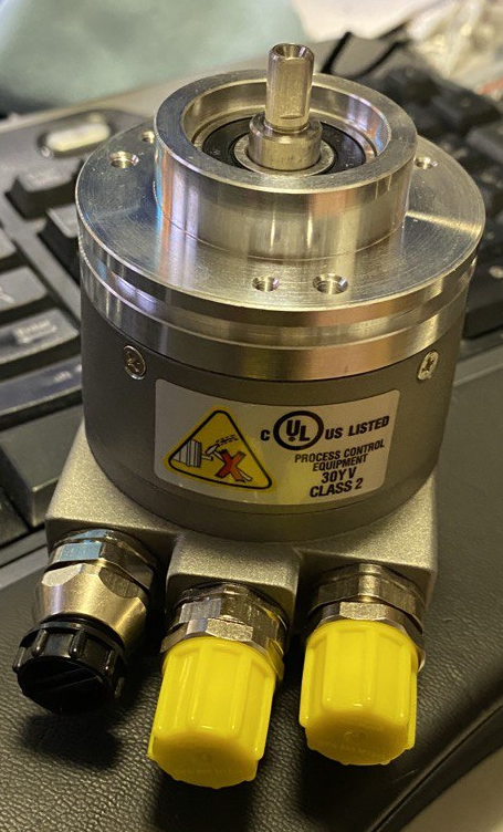
profibus, 16bit, absolute encoder
so 65536 positions in a circle or 320+ segments per single step of a 1.8degree stepper ... should get interesting results ")
-
@arhi that's a very nice encoder and optical based. Which I expect is better than the 14 bit based AMT212 encoders which is not optical and need middle speed for accuracy. There was a discussion about the AMT encoders in the forum in the past and whether encoders will be supported by rrf in the future.
-
@mendenmh this is impressive high accuracy!
-
@JoergS5 I do a lot of work for the military equipment manufacturers
this is military-grade stuff, precision is an order of magnitude higher than what they promise in datasheed and is used for some nasty things :(. Anyhow that's what I had available to do the testing with that was precise enough, I can't use it forever need to return it but I guess I can do some useful measurement on few steppers with it just for fun. Need to just get the profibus to work, my adapted is dead for some reason (have not used it for a while) ordered new one but will see in the meantime if I can hack something up myself...basic idea is to couple this to bunch of different motors and measure positional accuracy full step, half step ... 1/32 step both with open loop steppers, the BTR "closed loop" attempt and leadshine closed loop stepper. I don't have any nice servos to try but there it all really depends on the encoder. I just hope I can get something done till 11th as then the work starts and the free time is gooooooooooone
-
@arhi it would be valuable information to know how high the accuracy of the iHSV57 servos is *). But if you don't have one, then it's not possible for you unfortunately. Enjoy playing around with this encoder! I didn't find an information about the price of your encoder, but I suspect it is a thousand at least, because digikey has one encoder (other brand) with 65536 for this price.
*) this servo has a 1000 line closed loop encoder, but in a forum they said it is 4000 lines. It would be valuable to know how precise the servo is.
BTW think of me at 11th, this is my birthday.
-
@JoergS5 said in Stepper precision +-5%:
@arhi it would be valuable information to know how high the accuracy of the iHSV57
unfortunately, only thing closed loop that I have is HBS57 and that's stepper with encoder (iHSV57 is AC servo iirc)
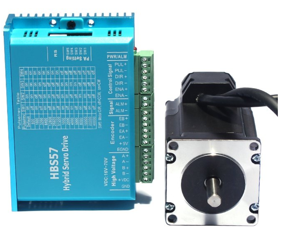
and this S42B pos

I didn't find an information about the price of your encoder, but I suspect it is a thousand at least, because digikey has one encoder (other brand) with 65536 for this price.
It's the type of equipment where they don't advertise the price and you don't ask for a price
if you need it you don't care how much it cost. But yes, the price is around 1000eur + all the taxes and customs and ... when you get them in volume. Never seen them being sold to individuals but there's probably a source available somewhere, these days you can purchase anything if you look hard enough BTW think of me at 11th, this is my birthday.
mine was on 1st so if I believed in astrology ... -
@arhi I want to standardize myself to the iHSV servos when I need fast and strong motors. They have 180 W (there is even a 400 W available) and for short time triple of it. I just ordered a 1XD card and will test the servo.
Belated happy birthday!
-
@arhi
I happen to have a new big open-loop 5phase stepper with drivercard (but no motion controller so you need to provide stp/dir/en) for another project lying here around. If you have interest in measuring it out, I could send it to you because I do not have any measurement equipment to see how accurate it is... but on those fairs the japanese/korean/taiwanese who push the 5-phase stepper always tell you microstepping accuracy is on another level compared to 2phase but of course I can fully understand if you got other things to do -
@DigitalVision said in Stepper precision +-5%:
@mendenmh said in Stepper precision +-5%:
The spacing of microsteps is also very load dependent. Under no load, it is roughly uniform, but because the magnetic interaction is strongest when you are on a full step (where the metal poles exactly align), the partial steps are much springier, and more load dependent, than the full steps. That is one of the reasons people like to make layer heights on 3d printers a multiple of full steps. Using anything else can result in moiré patterns on the layering axis.
@mendenmh, do you have a model for how the spring 'constant' varies with partial step positions? I've been assuming a roughly sinusoidal displacement/torque curve (as the figure below), modeling the region close to the stable point as a linear spring. I'd like to understand how much the slope of that region varies with the sub-step position.
Sorry for jumping in here - maybe that is of interest for you
:For 2-phase steppers (that is of course a totally different story for 3-&5-phase steppers) - in open loop of course - I read somewhere that the "truest" positions are Full-&Half-stepping, everything else just gets you more and more into the spring-area, more to read here:
https://www.faulhaber.com/en/support/technical-support/motors/tutorials/stepper-motor-tutorial-microstepping-myths-and-realities/
-> nice formula to calc the incremental torque M-inc = M-hfs * sin( (90*N) / ypfs) to calc/define the "real" torque on the shaft for the individual application to begin with. I personally think there is nothing wrong with low incremental torque because of microstepping (as long as people are aware of it and haven´t thought they would get the full-step-no-load torque also on each microstep which if you think about it does not make sense)After that a little intro:
https://www.zaber.com/w/Microstepping_Tutorial
-> "Quantization-/Detent-/Motor-pole/Stick-lip-Error" -> It might be possible, to even have to add Resistance-/Inductivity-Error to the list
And then the page I still feel to have only understood maybe a 1digit % of:
http://homepage.divms.uiowa.edu/~jones/step/micro.html
-> Figure 5.3Of cours this all applies to openloop 2phase steppers (in most modern high-end equipment uses closed-loop (FOC) 3-/5-phase equipment which is on a totally diffrent level which is also reflected in the price to pay for those). And since we want the best for our printers with the least money I think it is worth to dig deep how to accomplish the most with 2-phase openloop steppers!
Cheers
-
@LB said in Stepper precision +-5%:
@arhi
I could send it to youI'd love to test it out but the problem is I fear sending it to me would be too expensive, our customs officers are not known for their kindness
.. Where are you, maybe we can arrange something (I'm in Belgrade, Serbia)Providing step/dir is not a big deal, I have to do that for all the motors I will be testing too :), major problem I have is that none of my printers are operational as I could not get them up and running due to some injury (lasting more than a year
) so I got STL's to omni to print for me .. -
@LB said in Stepper precision +-5%:
the most with 2-phase openloop steppers!
for 3D printers I agree with you, but I am also planning to build a CNC, and there servos are preferred.
I would like to have information about how to best design the stepper - gear - belt/ball screw chain. E.g. when using full steps to avoid microstepping (microstepping only for noise reduction), then a big gear ratio => is this a good idea? And how big are the errors of the belts and pulleys in respect to the stepper and gear errors?
Example:
a) stepper with +-5%, no gear, 20 teeth pulley, GT2, turning 1.8 degree: stepper rotates between 1.71 and 1.89 degree, distance of belt between 0.19 and 0.21 mm => error 20 micrometer
b) stepper with +-5%, 1:200 gear, 20 teeth pulley, GT2, turning 360 degree: the stepper rotates between 359.91 and 360.09 degree, which results in belt distance between 0.19995 and 0.20005 => error 0.1 micrometer
Now the question, is the gear error bigger or smaller than the stepper's? -
exactly what I am currently exploring! Let´s crack this "nut"! (the biggest benefit of gearing is the torque you can gain beside the resolution IF accuracy of the belt can be guaranteed... -> Also the inertia lever is more beneficial because it increases/decreases ^2 if I remember correctly -> That is why most cnc´s use a 1:1,5 up to 1:5 belt for ohmp
)
-> But it might be wise to use also half-steps since those seem to be also quite accurate and pick a lower gearing to gain some end speed otherwise you might need a higher voltage (external) stepper to gain end speed -
@arhi said in Stepper precision +-5%:
@LB said in Stepper precision +-5%:
@arhi
I could send it to youI'd love to test it out but the problem is I fear sending it to me would be too expensive, our customs officers are not known for their kindness
.. Where are you, maybe we can arrange something (I'm in Belgrade, Serbia)Providing step/dir is not a big deal, I have to do that for all the motors I will be testing too :), major problem I have is that none of my printers are operational as I could not get them up and running due to some injury (lasting more than a year
) so I got STL's to omni to print for me ..Sorry to hear about your injury - all the best!
Would ship from germany -> is there any reliable parcel service like UPS or DPD that would work? -
@JoergS5 One of the magical properties of belts such as the gt2/gt3 designs is that they are almost completely free of backlash. They are easy to make perform much better than gears. A HUGE amount of money was put into making these belts work for ink-jet printers and the like. I suspect that a belt-driven system will be much easier to make work with high precision than a gear-driven system. It only takes a tiny bit of backlash to drive a servo-system crazy, if you are planning on reversing direction very often.
You still get to plan the reduction factors to work around microstepping defects, or at least make them easy to solve with a servo.
Another advantage of belts is that you can pick any ratio you want, instead of always having to find relatively prime tooth combinations to even wear. You can also set the shaft spacing independently (nearly) of the reduction ratio, since you can get belts in a wide variety of lengths.
Belts also engage much more of the circumference of the gear than you get in direct-geared systems. Thus, although one's first reaction is that belts aren't going to be as strong, it's no where near as big a factor as one might think. And belts with steel or glass backbones don't stretch very much as all.