Stepper precision +-5%
-
Most steppers are said to have a tolerance of full steps of +- 5%.
Does anyone know what's the reason for this +-5%?
- is it production tolerance of teeth?
- is it positional error because of inexact current flow or magnetic field
- some other reason?
My main question: if e.g. position shall be 100 and tolerance +- 5% means from 95 to 105, is it always at e.g. 102, or is it one time at 95, the next time 100, the next at 105? And what's the factor it depends on?
I ask because I think about whether it is possible to get more precise position results by software correction factors or not.
-
That number is the fraction of a step variation you might see from one step to another for an unloaded motor. Yes, it is due to magnetic inhomogeneities, and could be quite irregular around the full circle. Note that since a full circle add up to exactly 360 degrees and (usually) 200 full steps, for every step that is too big, there have to be small steps to make it all add up still. They can't all be 102%, since the number of steps per full circle is exact and constant.
Note that I use this principle to calibrate ultra-high precision x-ray diffractometry systems. With no external standards, and a highly repeatable (bot not accurate) angular scale, one can use 'circle closure', which is this property of cancelling errors, to define angular scales of truly extraordinary accuracy.
See, for example, https://www.ncbi.nlm.nih.gov/pmc/articles/PMC4911639/
which is one of the papers I have published on this technique. The technique has been used since the 1800's (!). -
@mendenmh thanks a lot for your expert answer!!
I skimmed over the article, it' s very interesting, I'll study your results.
-
@mendenmh said in Stepper precision +-5%:
That number is the fraction of a step variation you might see from one step to another for an unloaded motor.
Does this mean that the no load stopping accuracy of the motor is +/-5% of the angle of a single full step?
-
Does this mean that the no load stopping accuracy of the motor is +/-5% of the angle of a single full step?
@zapta That is probably not an inappropriate assumption. Of course, under load, the error can be arbitrarily large (up to the point where is starts skipping steps!).
The spacing of microsteps is also very load dependent. Under no load, it is roughly uniform, but because the magnetic interaction is strongest when you are on a full step (where the metal poles exactly align), the partial steps are much springier, and more load dependent, than the full steps. That is one of the reasons people like to make layer heights on 3d printers a multiple of full steps. Using anything else can result in moiré patterns on the layering axis.
-
@JoergS5 said in Stepper precision +-5%:
Most steppers are said to have a tolerance of full steps of +- 5%.
Yep, I guess you mean for a 2phase stepper with 1,8° with a 50tooth-rotor, then yes... even for those types you find companies like "Koll...gen", "Lin-...ring" and "J...L" and "St...ra" and so on that offer steppers with less - they usually deal only with companies and not with private end-users so you might have to find another way to get to some of those
but it is simpler (depending on your application and stepper-model) to e.g. (if you do not need high speed) to take a 2phase stepper with a 100-teeth-rotor which are those 0,9° motors then, which have inherently smaller full-step-no-load variation on the hardware-side
(If you ditch 2phase, you can find very high accuracy 3-phase and 5-phase 100-teeth-rotor motors, but often they are not for consumers and with minimum order quantity of 100/200/...pieces and more... also they (for now) would not be compatible with the duet-boards which support 2phase because they are the most widley used since those super high accuracy is normaly not needed on a 3d-printer since effects like mfg tolerance and thermal elongation of your axis/housing and belts and spindles e.g. are for too rough with most common low-cost printers to invest in such a high-end motor)
Does anyone know what's the reason for this +-5%?
- is it production tolerance of teeth?
- is it positional error because of inexact current flow or magnetic field
- some other reason?
I guess all of that
") with "inexact current flow or magnetic field" you are referring to the tolerance of mH & R in each winding and the tolerance of the magnets
with "inexact current flow or magnetic field" you are referring to the tolerance of mH & R in each winding and the tolerance of the magnetsIf money is no constrain, I heard you can ask companies to hand match or hand sort those for you, but if in modern software-times they are still doing it, the price of the motor will be *10 to *50 with minimum quantity order around 10 or more of that of a normal motor. So no option for the avarage user here.
Smarter to use software to save that money by waiting for the closed-loop-duet-motor-pcb that I read somewhere is in the making for 2021 for all duets that support CAN-bus, that can take care for some of the effects
My main question: if e.g. position shall be 100 and tolerance +- 5% means from 95 to 105, is it always at e.g. 102, or is it one time at 95, the next time 100, the next at 105? And what's the factor it depends on?
the "hardware-error" is not changing at all. It is fix as your hardware is fix. It is also (of course if you think about it) not cumulative over 1 electrical rotation and not cumulative over 1 physical rotation of your motor
If you use software-stuff like motor-idle-current-reduction in combination with very-high micro-stepping it is not helping on the accuracy-side, since the incremental-torque from micro-step to micro-step of course decreases with micro-step amount higher (the full-step absolute still-stand torque of course is always the same) and if you stop on one of these microsteps and even reduce current you are likely to get a spring-effect/-deviation - which is super tiny and should be gone if the motor is back to 100% current (when moving again) but even if it is supertiny it is there
I ask because I think about whether it is possible to get more precise position results by software correction factors or not.
-> go for a good 0.9° motor. The electro-magnetic-spring-effect of +-2 full-steps (half of an electrical revolution to both sides up to the tipping point of loosing a step) is of course half as big as with a 1.8° motor...
-> Check inertia-moment & torque for your application (otherwise you get a "magnetic"-spring effect from your motor if inertia-moment and torque are not matched/too low, which is also very important for accuracy regarding a motor
If you happen to need also high speed, look that the inductance (mH) is low of that motor, and that you use the highest voltage avaliable for your duet-board.
Use a stepper-motor-calculator (often for mH you might need the "advanced"-settings) like the one from our user now moderator "wilriker" (e.g. search this forum here for wilriker and motor calculator)
Regards
-
@LB Thank you for your input. I must confess, my opinion about steppers was very biased because of the offering on ebay. Thank you to propose looking for better steppers. I will test 0.9 steppers first.
With inexact current flow I meant the stepper driver, but there are multiple sources of inexact current and magnet fields.
I will try building a measuring station to select the steppers with good quality. I will analyze the iHSV57 too, which is a closed loop servo, for precision. I think about building a station like described in https://hackaday.com/2016/08/29/how-accurate-is-microstepping-really/ with laser pointers.
-
@JoergS5 said in Stepper precision +-5%:
@LB Thank you for your input. I must confess, my opinion about steppers was very biased because of the offering on ebay, where are only offered some Nanotec steppers, but rarely Kollmorgen or Lin. Thank you to propose looking for better steppers. I will test 0.9 steppers first.
welcome
(most companies nowadays usually have their motors produced (not even anymore in licence) by certain over-sea mfg (though they do quality inspection in e.g. germany to the high tüv/iso/... standards)) (- it seems beside highly specialized small companies, there seems to be no bigger mass-market european stepper manufacturer any more - they only do quality inspection here in europe. I heard even the JP have outsourced the older entry-level steppers and only manufature the new/latest/high-end motors in their own main-plant any more. So no matter how you choose the manufacturing will be most likely in outsourced sites to a low-income country plant, etc. and by choosing a company with reputation, the only benefit that you most likely will get, will be an inspection with TÜV/ISO etc. pp.
BUT I heard, that e.g. lin-...ing, koll...gan, phyt.../...gra, etc. pp. still produce within the main-plant of the company themself as far as I know - but even that is no guarantee to precision I guess -> anyway best to measure)With inexact current flow I meant the stepper driver, but there are multiple sources of inexact current and magnet fields.
I will try building a measuring station to select the steppers with good quality. I will analyze the iHSV57 too, which is a closed loop servo, for precision. I think about building a station like described in https://hackaday.com/2016/08/29/how-accurate-is-microstepping-really/ with laser pointers.
If you really want to build up a test station like this, I would recommend you integrate a "variable load" because no-load-full-step precision is not really what we have in reality in a printer, we need "dynamic precision" so to say, that means precision regarding to the accel/decel with load - that would really be cool if you do that and share and I guess a benefit for most users here
Regards
-
@LB I'll try to take into account dynamic aspects. There will be much discussion about s-curve etc. with the emerging RRF3.4.
The roadmap is in https://forum.duet3d.com/topic/20602/reprapfirmware-road-map-q1-2021 -
@JoergS5 said in Stepper precision +-5%:
@LB Thank you for telling the companies I can check for good quality. I already knew Kollmorgen, they are often mentioned in CNC forums.
I'll try to take into account dynamic aspects. There will be much discussion about s-curve etc. with the emerging RRF3.4.
cool
but most of them do not sell to individual end-users but only to companies but I guess you can get creative there you might also check out moon...-...tors since they ship from 1 piece on and within a few days to private-person-end-users. Since you seem to be from ger...ny you might consider to give a phone-call to companies like mech...pro, colo...-...nik, dol...-...onik and or sor...tec, and alike etc. pp., they can help you out, if you know what you want.-> Before I would make sure to have used a stepper-calculator and or "how to choose a stepper motor" in advance. To know what you need for sure you know that you have to check the max. A the stepper-drivers of the duet-boards can provide?
(If you do also attach a laser-pointer why bother with sin/cos/tan because of projecting on a flat wall, rather put the stepper-face-plate to the wall and tilt the laser also in a way that it is not parallel any more to the motor-rotor-axis, so to have "quasi" a 360° clock-like circle projected
and if you need more resolution just increase the circle-diameter of the "circle" -> maybe more precise if you happen to get one of the big school-"geodreieck" or a goniometer or angle-metre? But that is only what I would do you might just ignore this idea here)Looking forward to hear about it ( - last post from me with this kind of info
") )
) -
@LB thank you for your ideas, I'll consider all ideas in the thread. I love measuring and will try to improve the 3d printer.
-
This post is deleted! -
This post is deleted! -
@JoergS5
Found that for a "printed" angle-gauge:
https://reprapltd.com/3d-printed-angle-gauge/
-> it is really cool to generate a template https://www.blocklayer.com/protractor-print.aspx for a copy-shop for a big plot -
@mendenmh said in Stepper precision +-5%:
The spacing of microsteps is also very load dependent. Under no load, it is roughly uniform, but because the magnetic interaction is strongest when you are on a full step (where the metal poles exactly align), the partial steps are much springier, and more load dependent, than the full steps. That is one of the reasons people like to make layer heights on 3d printers a multiple of full steps. Using anything else can result in moiré patterns on the layering axis.
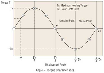
@mendenmh, do you have a model for how the spring 'constant' varies with partial step positions? I've been assuming a roughly sinusoidal displacement/torque curve (as the figure below), modeling the region close to the stable point as a linear spring. I'd like to understand how much the slope of that region varies with the sub-step position.
-
@LB said in Stepper precision +-5%:
@JoergS5
Found that for a "printed" angle-gauge:
https://reprapltd.com/3d-printed-angle-gauge/
-> it is really cool to generate a template https://www.blocklayer.com/protractor-print.aspx for a copy-shop for a big plotI already used this principle
https://forum.duet3d.com/topic/14996/five-bar-parallel-scara-prototypes/10
-
@DigitalVision No, I don't have a specific model for how the torque varies with offset from the center. The graph you attached is probably a very good guess, for a motor sitting right one a step. I would expect the behavior to be more complex at (say) a half-step boundary, where the two poles are pulling equally.
In work I do professionally, where such things matter, we use encoders to read the actual angles, rather than depending on any good behavior of the stepper, or gearing, or anything else. Of course, by the time we are done, one axis costs about $5000, and is accurate to 0.05 arcseconds (1/72000 degree!). Such a system lives in a room with 0.01C temperature control, too.
-
@mendenmh said in Stepper precision +-5%:
@DigitalVision No, I don't have a specific model for how the torque varies with offset from the center. The graph you attached is probably a very good guess, for a motor sitting right one a step. I would expect the behavior to be more complex at (say) a half-step boundary, where the two poles are pulling equally.
Thanks. I did a quick and very simple and crude simulation model myself and found that although the behavior was very dependent on the model parameters, it seemed feasible with the right tooth design to design a fairly flat torque curve across micro step positions if you use cos-sin phase current control. I have no idea how that trades against other aspects though and how real steppers behave.
In work I do professionally, where such things matter, we use encoders to read the actual angles, rather than depending on any good behavior of the stepper, or gearing, or anything else. Of course, by the time we are done, one axis costs about $5000, and is accurate to 0.05 arcseconds (1/72000 degree!). Such a system lives in a room with 0.01C temperature control, too.
That's incredibly cool.
-
I took this baby today from another project

https://www.kuebler.com/us/products/measurement/encoders/product-finder/product-details/5858_PROFIBUS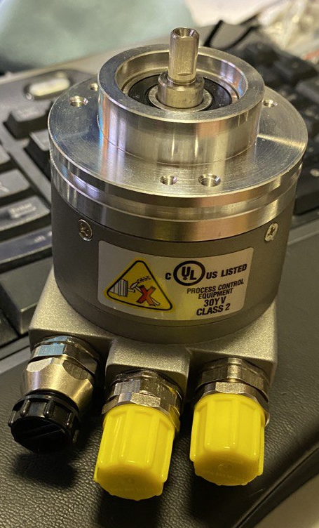
profibus, 16bit, absolute encoder
so 65536 positions in a circle or 320+ segments per single step of a 1.8degree stepper ... should get interesting results -
@arhi that's a very nice encoder and optical based. Which I expect is better than the 14 bit based AMT212 encoders which is not optical and need middle speed for accuracy. There was a discussion about the AMT encoders in the forum in the past and whether encoders will be supported by rrf in the future.