Bug? In Retraction and Movement Junction
-
I decided to try printing a few of these cylinders.
I'm running an E3D V6 through about a 400mm bowden tube, so although I get reasonable prints, it's not an exceptional printer.
I used Prusa Slicer and have seams "aligned" which in this test I believe is worst case scenario.
I've used ABS at my normal settings.I definitely get a small seam at the start/finish.
Looking at the G Code that Prusa Slicer gives me, there is no retraction or un-retraction in this area. I have it set to not retract when travel moves remain within the perimeter.
So retraction can't be the cause of the seam (in my case), nor any "pause" you may notice. I couldn't see any such pause when the tool moved from one perimeter to the next, but if the were a retract I would expect one.
Some of the posts above suggest your slicer IS doing retractions and/or unretractions at the junction.I set Prusa slicer to alter the pressure advance every layer from zero up to the current Z height divided by a factor.. Over four prints that factor was 1000, 500, 100, 10
So in effect, I tried various levels of pressure advance from zero to levels which gave me terrible prints, but nothing changed the seam.I therefore feel pressure advance has nothing to do with it.
My normal PA setting is 0.09
Given the very small line segments we're talking about here I don't know how much pressure advance could actually be applied/useful in this object.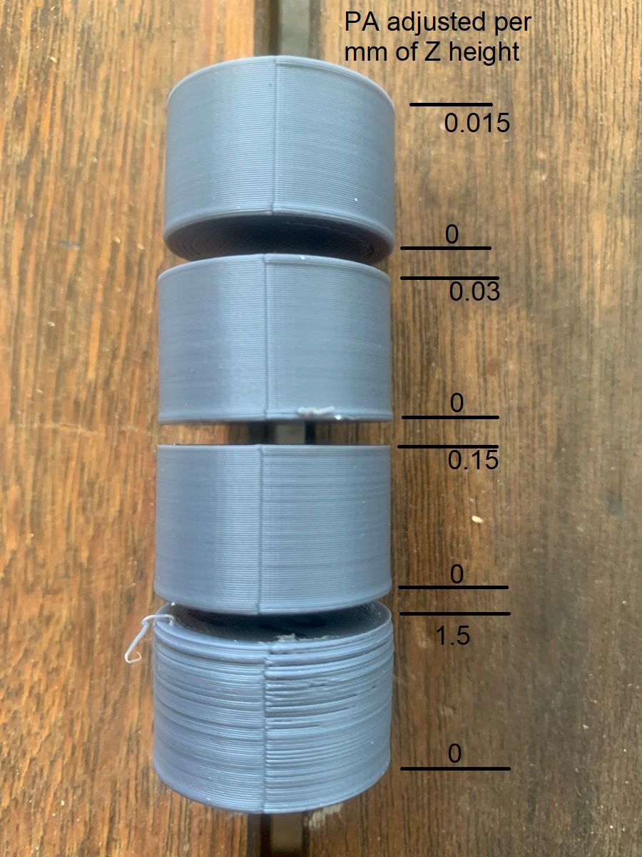
I believe the reason is that the tool orifice is round and the tool path generated by the slicer never fully over laps the centers.
Therefore even with perfect extrusion, there will always be a slight divot.
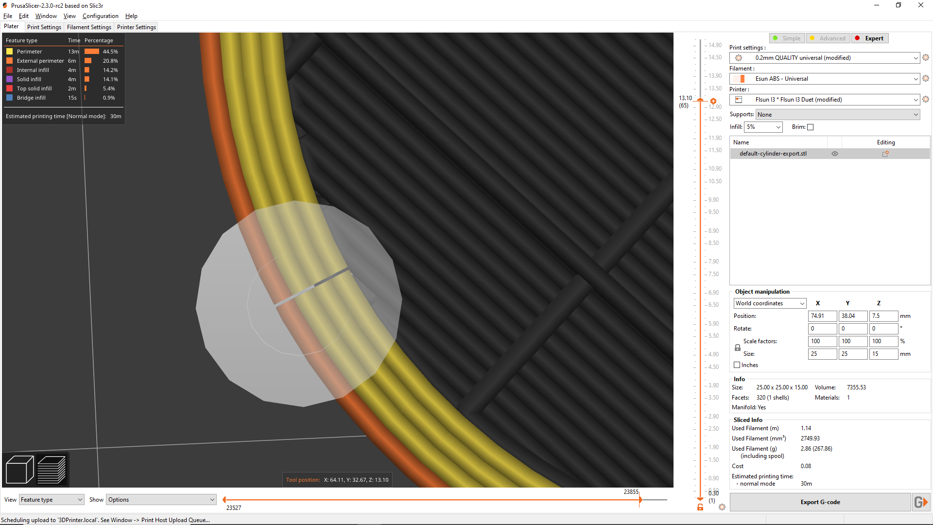
This is what prusa slicer shows
this is what a Gcode analyzer shows
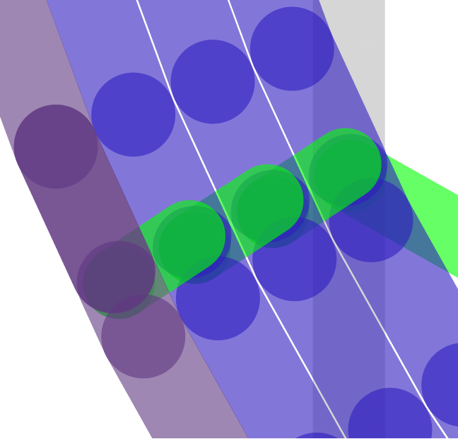
This is what it looks like if I draw the points in CAD
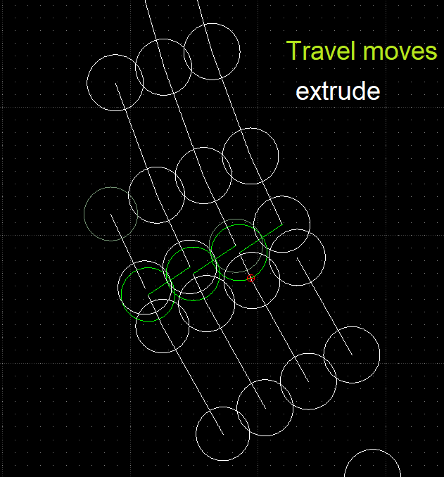
The green lines are travel moves (albeit short)
The green circles represent the point where extrusion for that perimeter will start.
The white lines are the travel path.
So given that during the travel move the nozzle pressure is (presumably) dropping, I think that the start of the next travel move will have a slightly narrower extrusion width than when at full pressure, so the start of the line would be more like a teardrop.
It would also bend inwards at the change of direction slightly.
Couple that with the fact that the toolpath stops short of the same point at the end and you have to intersecting circular points that don't meet up at a point where the extrusion is the same width.
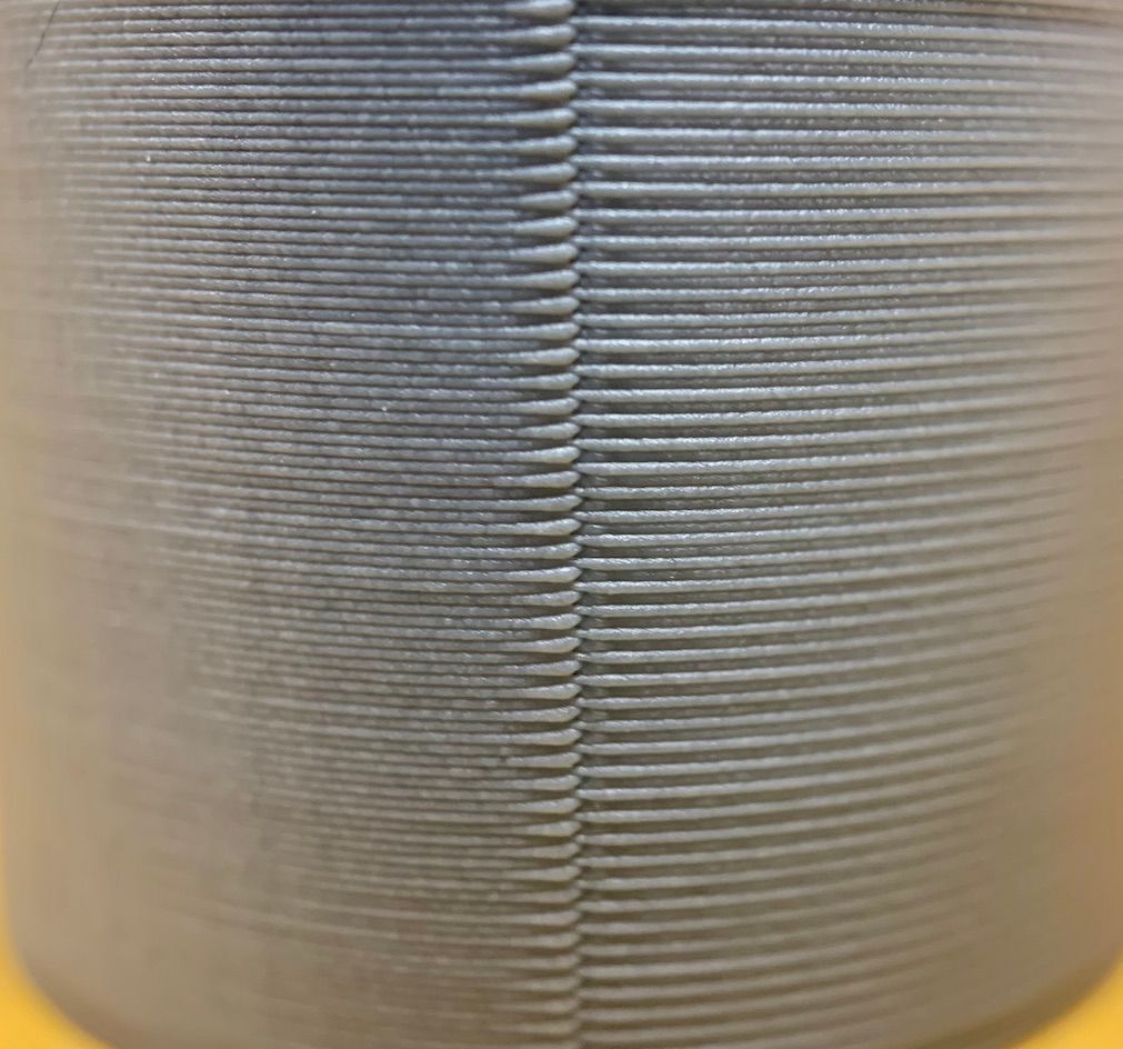
By stopping the print early, you can see the variation in extrusion width in the area, although the nozzle travel move effectively "wipes" the junction so you can't see lines at that point.
It's actually clearer on the first layer, but I use different layer height and extrusion factors there so it may not be entirely representative.

If the tootlpath did meet up on center I'd expect a bulge, so I fully understand why the slicer uses the path that it does.
It'd take some custom G code generation to test it I guess.So in conclusion I'm struggling to see how RRF is the cause of this if it's only following the toolpath provided?
Nor do I see how Marlin would do anything different in this scenario, but I can't test that and don't discount your experience.
Unless there's something going on in the background of the firmware in terms of junction deviation at these travel moves I can't offer any answers that would point to a difference that could be attributed to firmware?
Someone with more in depth knowledge of the firmware would have to weigh in on that. -
Sorry this has been an.. lets go with an emotional day so my testing started late today.
Im still running a number of tests with the new 3.2 firmware as well as attempting to try and tune the motion system better..
As I mentioned in my very first post, slicer does not matter.
I am well aware prusaslicer's default settings do no use retraction usually in this junction.
However to rule out that therefore its not related to the issue is a little short-sighted and rather just raises more concern.
Your analysis as stated would mean that prusa's own machines print with results like this, my A/B prints show a print off my Prusa Mini which was sliced with prusaslicer and does not have this issue as shown. (powered by marlin)However in saying this. This actually further proves at least to me there is indeed some sort of issue in the junction planning on RRF. You don't see the pause because your not retracting but still see the issue I see. This issue wouldn't matter to me if it was a issue found in marlin, having used marlin for several years prior to RRF I can for sure say this issue does not exist in marlin which is why it sticks out as a issue to me in RRF.
While I am currently still running tests for firmware 3.2 currently I can say the results are.. sorta? better? ish? may just not as predominate for sure still producing more or less same issue. Again with minimal influence by Pressure Advance settings as im currently running PA towers right now to see how it changes. I can say my same settings and gcode as posted before in this thread produces basically the same results.
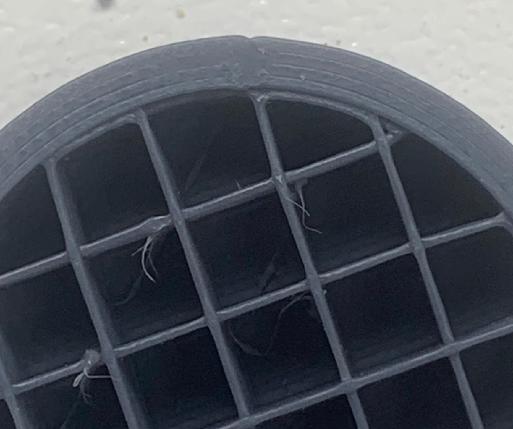
Using low values encourages more of a bulge on the stop point and when the value is increased enough to resolve that, the start point is under extruded causing the same "step" effect in the surface. Im not referring to a seam, im referring to a miss-matched surface.
(
General like the image above, while this is normal with a PA value that is too high causing under extrusion. My issue is similar except the start point is the correct width but the stop section is larger than the nozzle diameter.I am not the only person with this issue i know many people with this issue that have shelved their RRF powered machines or just completely pulled the board out and loaded a Marlin powered board in the machine.
As I have mentioned in my first post, every time this issue comes up everyone either writes off the issue as resolved when its not, or just abandons the thread. Usually resulting in the user being frustrated and discarding the duet product for something else.
-
@jatmn, have you tried using jerk policy 1 with RRF 3.2 yet?
Duet WiFi hardware designer and firmware engineer
Please do not ask me for Duet support via PM or email, use the forum
http://www.escher3d.com, https://miscsolutions.wordpress.com -
Also, increase your X/Y jerk above 3 mm/s. Make it 10 mm/s for a test.
-
@bot Well he did try these settings: https://forum.duet3d.com/post/202855
M566 X900 Y900 Z120 E3000               				; set maximum instantaneous speed changes (mm/min)
M566 P1                                            ; Set jerk policy to mimic Marlin and uses jerk between all moves.
M203 X12000 Y12000 Z600 E6000          				; set maximum speeds (mm/min)
M201 X4000 Y4000 Z300 E3000             				; set accelerations (mm/s^2)
M204 P800 T2500								   ; set print and travel accel
M572 D0 S0.035 ; PRESSURE ADVANCE
M207 S1 R0.0 F3000 T1500 Z0.0 ; firmware retraction
I thought the results looked better, but
¯\_(ツ)_/¯I think that was only with 3.1.1 though, and not 3.2.
-
@dc42 said in Bug? In Retraction and Movement Junction:
@jatmn, have you tried using jerk policy 1 with RRF 3.2 yet?
yes
-
@Phaedrux said in Bug? In Retraction and Movement Junction:
@bot Well he did try these settings: https://forum.duet3d.com/post/202855
M566 X900 Y900 Z120 E3000               				; set maximum instantaneous speed changes (mm/min)
M566 P1                                            ; Set jerk policy to mimic Marlin and uses jerk between all moves.
M203 X12000 Y12000 Z600 E6000          				; set maximum speeds (mm/min)
M201 X4000 Y4000 Z300 E3000             				; set accelerations (mm/s^2)
M204 P800 T2500								   ; set print and travel accel
M572 D0 S0.035 ; PRESSURE ADVANCE
M207 S1 R0.0 F3000 T1500 Z0.0 ; firmware retraction
I thought the results looked better, but
¯\_(ツ)_/¯I think that was only with 3.1.1 though, and not 3.2.
these settings were tested again on 3.2 results was basically same as in 3.1.1
-
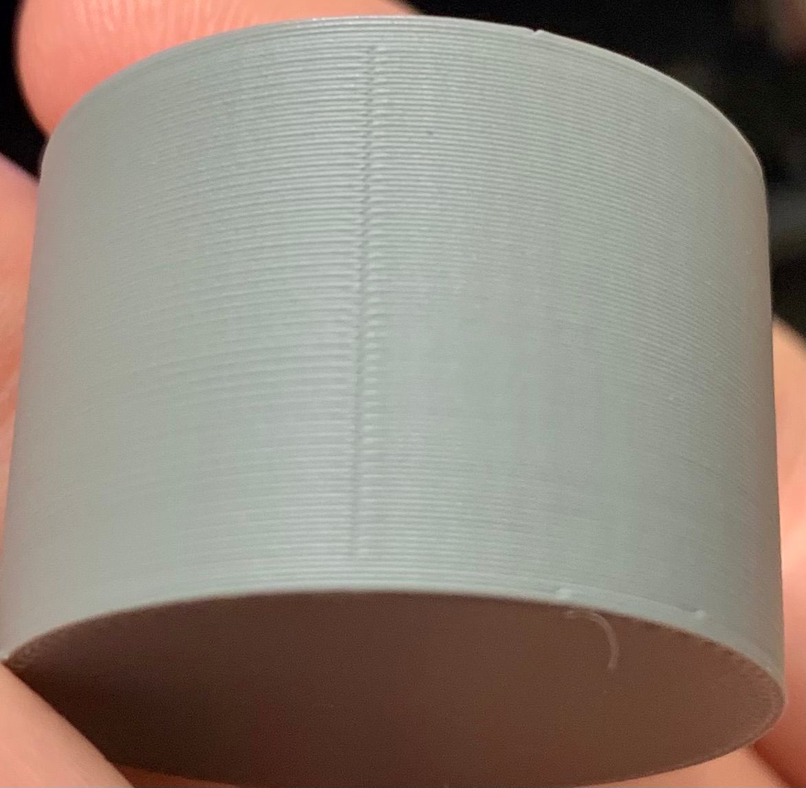
Can you show a comparison photo of the results of those settings and the print from the PrusaMini?
-
That was posted above already, but here it is.
Grey was RRF
Red was Prusa Mini

-
currently my only running machine is a modified prusa mk2 . still using marlin .
if i'm using retraction , its easy to tune the seam to be a bulge or a void . invisible seam is impossible .
i dont see how its not tunable with rrf , same way it is with marlin .
i will try to connect it to duet board and compare. -
@jatmn having finished another bit of detailed investigation i am now looking at this. The video and pictures are helpful, along with the detailed description.
Is it a fair to say in summary the key difference in that on a Z seam there is a "bulge then gap" effect, where as the mini/marlin printed part is something of a gap with no bulge?
Will look to recreate this using your posted gcode and settings, although i don't have an identical machine - should be able to get close.
-
@T3P3Tony That is correct a "bulge than gap" and in my tests pressure advance has more effect on the gap and start point and less of an effect on the stop (bulge). Values high enough to affect the bulge result usually in a significant gap (actually a hole all the way thru) and under extruded start point.
-
@jatmn thanks, I am going to be testing without PA initially to help rule that out.
-
For what it's worth - I also have been experiencing less-than-optimal seam performance as well, similar series of troubleshooting steps, PA tuning, jerk/speed/accel adjustments, slicer tweaks, slicer changes, hardware updates, and the like on 3.2 (and earlier betas) I do not use aligned seam, so the bulges are everywhere and are just tiny zits.
I haven't changed my jerk policy yet and will change that to see if it resolves, but I eagerly anticipate the results from the work you all are doing.
-
@jatmn Just as an update I did a number of cylinder prints here on a delta and e3d toolchanger. I can see a similar seam presentation as you showed with some variation between slicers (Cura, ideamaker, Prusa slicer) but not enough to be conclusive. I also tried the latest beta firmware and spent a not entirely fruitful time with pressure advance settings.. I ended up ordering a well regarded small printer that does not run RRF to use as a comparison machine. It will be interesting to set it up with both control options and run the same gcode through to see what changes.
-
I'm having quite the similar printer, Bondtech extruder, Bear frame and so on with Duet 3 Mini 5+ and RRF 3.3b2.
So I also did a test cylinder and like to share my results. Printed in PLA with PA set to 0.056.
-
@Argo Perfect!
-
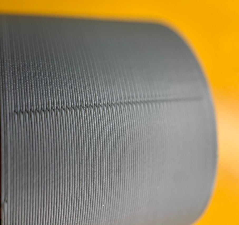
It looks like the seam is showing "bulges" only on alternate layers.
IF that is what is happening how are you doing that?
Thanks.
Frederick
-
It looks like it's alternating the layer seam.
-
You are right, it's alternating the layer seam.
I've made another picture closer to the print where you can see this more clearly.
I'm using SuperSlicer (inofficial branch of PrusaSlicer):