Duet3D Logo Duet3D
    • Tags
    • Documentation
    • Order
    • Register
    • Login

    Request change to wiring diagrams

    Scheduled Pinned Locked Moved
    General Discussion
    8
    20
    889
    Loading More Posts
    • Oldest to Newest
    • Newest to Oldest
    • Most Votes
    Reply
    • Reply as topic
    Log in to reply
    This topic has been deleted. Only users with topic management privileges can see it.
    • zaptaundefined
      zapta @gnydick
      last edited by

      @gnydick said in Request change to wiring diagrams:

      This is very confusing because the naming convention here also uses A and B.

      +1 for confusing. I hit the same issue recently when working on the stepper motor analyzer. First did it the intuitive way and then changed to the Duet's way. 😉

      Most of the notation I have seen, including in Wikipedia, letters denote coils and digits or +/- denote polarity.

      As for using multimeter, can it be used to determine the coil association on the Duet's connector pins?

      1 Reply Last reply Reply Quote 0
      • gnydickundefined
        gnydick @fcwilt
        last edited by

        @fcwilt exactly, lol

        1 Reply Last reply Reply Quote 0
        • zaptaundefined
          zapta
          last edited by

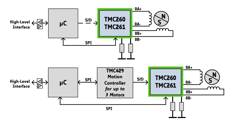
          Here is the coil outputs notation in the Trinamic datasheet.

          2021-02-05_20-51-34.png

          gnydickundefined 1 Reply Last reply Reply Quote 0
          • gnydickundefined
            gnydick @zapta
            last edited by

            @zapta yes, thank you!

            1 Reply Last reply Reply Quote 0
            • A Former User?
              A Former User
              last edited by

              there is more documentation for those in need; https://duet3d.dozuki.com/Wiki/Choosing_and_connecting_stepper_motors#Section_Using_the_internal_drivers with less room for ambiguity.

              (it also shows maestro and duet3 having been changed already)

              zaptaundefined 1 Reply Last reply Reply Quote 0
              • dc42undefined
                dc42 administrators
                last edited by

                @gnydick, we agree with you. That's why all our more recent boards, including all production Duet 3 series boards, label the outputs A+ A- B+ B-.

                Duet WiFi hardware designer and firmware engineer
                Please do not ask me for Duet support via PM or email, use the forum
                http://www.escher3d.com, https://miscsolutions.wordpress.com

                1 Reply Last reply Reply Quote 3
                • zaptaundefined
                  zapta @A Former User
                  last edited by

                  @bearer said in Request change to wiring diagrams:

                  (it also shows maestro and duet3 having been changed already)

                  Very good. We were knocking on an open door. 😉

                  1 Reply Last reply Reply Quote 0
                  • Swift Testerundefined
                    Swift Tester @gnydick
                    last edited by

                    @gnydick said in Request change to wiring diagrams:

                    At the very least, you could put a comment on the wiring diagram that tells you 1 & 2 are the different coils and to NOT map A & B to the motor diagram's A & B.

                    For Duet 2 this suggestion looks reasonable.

                    1 Reply Last reply Reply Quote 0
                    • T3P3Tonyundefined
                      T3P3Tony administrators
                      last edited by

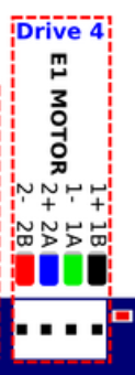
                      I have updated the wiring diagram:

                      b313593b-634f-4fa1-a02d-332566c8886d-image.png

                      www.duet3d.com

                      gnydickundefined 1 Reply Last reply Reply Quote 4
                      • gnydickundefined
                        gnydick @T3P3Tony
                        last edited by

                        @T3P3Tony thank you for the effort, but that's more confusing. The whole point was that all the motor diagrams seem to indicate A loop and B loop. This new diagram only makes sense if you understood it to begin with. Keep in mind, I'm viewing this from the "n00b" point of view. I'm suggesting making it fool proof, as there are lots of little pitfalls that can result in $200 mistakes.

                        T3P3Tonyundefined 1 Reply Last reply Reply Quote 0
                        • T3P3Tonyundefined
                          T3P3Tony administrators @gnydick
                          last edited by

                          ahh ok, fine, changed to that.

                          www.duet3d.com

                          1 Reply Last reply Reply Quote 0
                          • Swift Testerundefined
                            Swift Tester
                            last edited by

                            Don't want to seem boring, but according to
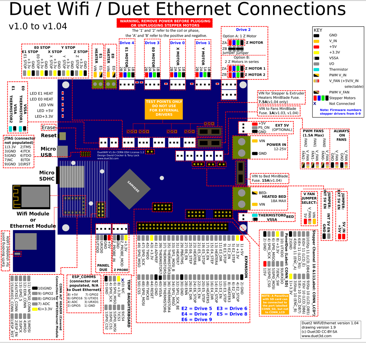
                            "On Duet 2 WiFi/Ethernet these are labelled '2B 2A 1A 1B' on the back of the board, and on the wiring diagram. The '1' and '2' refer to the coil or phase, the 'A' and 'B' refer to the positive and negative."
                            "+" and "-" are currently reversed.

                            T3P3Tonyundefined 1 Reply Last reply Reply Quote 0
                            • T3P3Tonyundefined
                              T3P3Tony administrators @Swift Tester
                              last edited by

                              @Swift-Tester thats why i left the original labelling on the diagram as well as the AB+- which is to help those like @gnydick who are referring to a diagram labelled with AB+-

                              The +/- are consistent with other Duet diagrams that use this scheme (i.e. black is A+ etc)

                              www.duet3d.com

                              1 Reply Last reply Reply Quote 0
                              • T3P3Tonyundefined
                                T3P3Tony administrators
                                last edited by

                                basically as long as you realise that the two pairs are on pins 1,2 and 3,4 respectively its all good, you can use M569 to set the motor direction as required.

                                www.duet3d.com

                                1 Reply Last reply Reply Quote 0
                                • Swift Testerundefined
                                  Swift Tester
                                  last edited by

                                  I do not have the source, but IMHO this sketch is consistent with Wiki and have the information about special notation D2W uses. The rest is up to the reader.

                                  b4953bf7-ee25-4caa-b316-1961d534df69-image.png

                                  1 Reply Last reply Reply Quote 0
                                  • First post
                                    Last post
                                  Unless otherwise noted, all forum content is licensed under CC-BY-SA