Lead screw nut - brass vs POM and radial clearance/backlash
-
I have been fighting z banding on my core xy for a while now. I've changed my lead screws (I bent the first ones), redesigned the rails, changed how I mount the lead screws (they used to be over constrained), and even done a dance for the printer gods! It's got better, but not disappeared.
That's when I realised I've been using the same cheap brass lead screw nuts since I first built the printer a few years ago. Turns out that they have some significant radial clearance in them. Like I can wobble the lead screw about 0.5mm sideways in them. Axially they're not too bad, and it's z axis so not really been a concern. I'm using three Tr8 lead screws with 2mm pitch to support the bed and they're all about the same.
I've just bought some new POM lead screw nuts to try and they are a very snug fit (almost tight). So I got wondering what other people's thoughts/experiences were. Do you use brass nuts, or plastic and how snug do/should they fit? I'm also toying with fitting anti-backlash ones though think it might be a bit overkill for a z axis and make them wear out even faster.
-
I'd be interested to see if you notice a difference with the POM nuts. Do they need to be lubricated as well?
I wouldn't bother with the anti-backlash nuts since the weight of the bed should remove any backlash anyway.
-
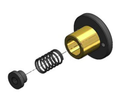
I am using TR8 8mm lead, 2mm pitch nuts like the ones below. They came with my Z steppers. Only POM touches the screw and I think that the anti-backlash helps holding the bed in place when power is off (310 x 310 x 6 aluminum plate).
BTW, tried once to switch to 2mm lead screws, everything looked good but got z-banding to went back to the original 8mm lead. Not sure what caused the z banding.
-
You might want to look into 1204 ball screws, that's what's drives cnc machines. Their way more efficient / servicable than any lead screw brass bronze or pom nut. You can get them on amazon or eBay for around 40-50$ a piece
-
POM should be just fine. They came with the motors, never had an issue.
People often over or under constrain the z-axis rails, that coupled with things like failing to control movement in the build surface makes the Z axis more complicated than people expect
(Seriously, I saw a real retail printer that had at least 1mm of lateral play in the build surface... all prints had Z banding due to that fundamental design flaw).
The key thing is to have the rails be square/true/parallel and able to control the bed, the leadscrew should almost be floating.
If you are getting consistent z banding after the changes you describe, I would look closely at all the other things that could be moving (assuming that it's not the classic red herring of a dodgy PID tune).If you want to have the bed stay in position, an 8mm lead isn't going to help. Its good for speed, but a 4mm lead might be a better compromise.
I've never seen a difference with anti-backlash on Z. Either the axis is well enough designed that it doesn't matter (due to gravity) or the axis is not well designed and has other issues.
-
Are your screws direct coupled to the motors or are they driven with pulleys and belts?
-
@Phaedrux They're now fitted
") Initial result from a test cube is that they are a bit better (though that may be my old brass ones were that bad!), but I still have some Z-banding. I still need to have a bit of a play round with how I've mounted the lead screws. Something I did realise is that they deform a but if you press-fit them into your 3-D printed mount. I was a bit lazy when putting them in at first and didn't check the hole dia before shoving them in. It squished the nut a bit meaning it bound up on the lead screw and wouldn't rotate. bit of re-dressing of the printed mount and they run much better
Initial result from a test cube is that they are a bit better (though that may be my old brass ones were that bad!), but I still have some Z-banding. I still need to have a bit of a play round with how I've mounted the lead screws. Something I did realise is that they deform a but if you press-fit them into your 3-D printed mount. I was a bit lazy when putting them in at first and didn't check the hole dia before shoving them in. It squished the nut a bit meaning it bound up on the lead screw and wouldn't rotate. bit of re-dressing of the printed mount and they run much betterOne definite positive is that they are black, so at least look good on my white printed parts

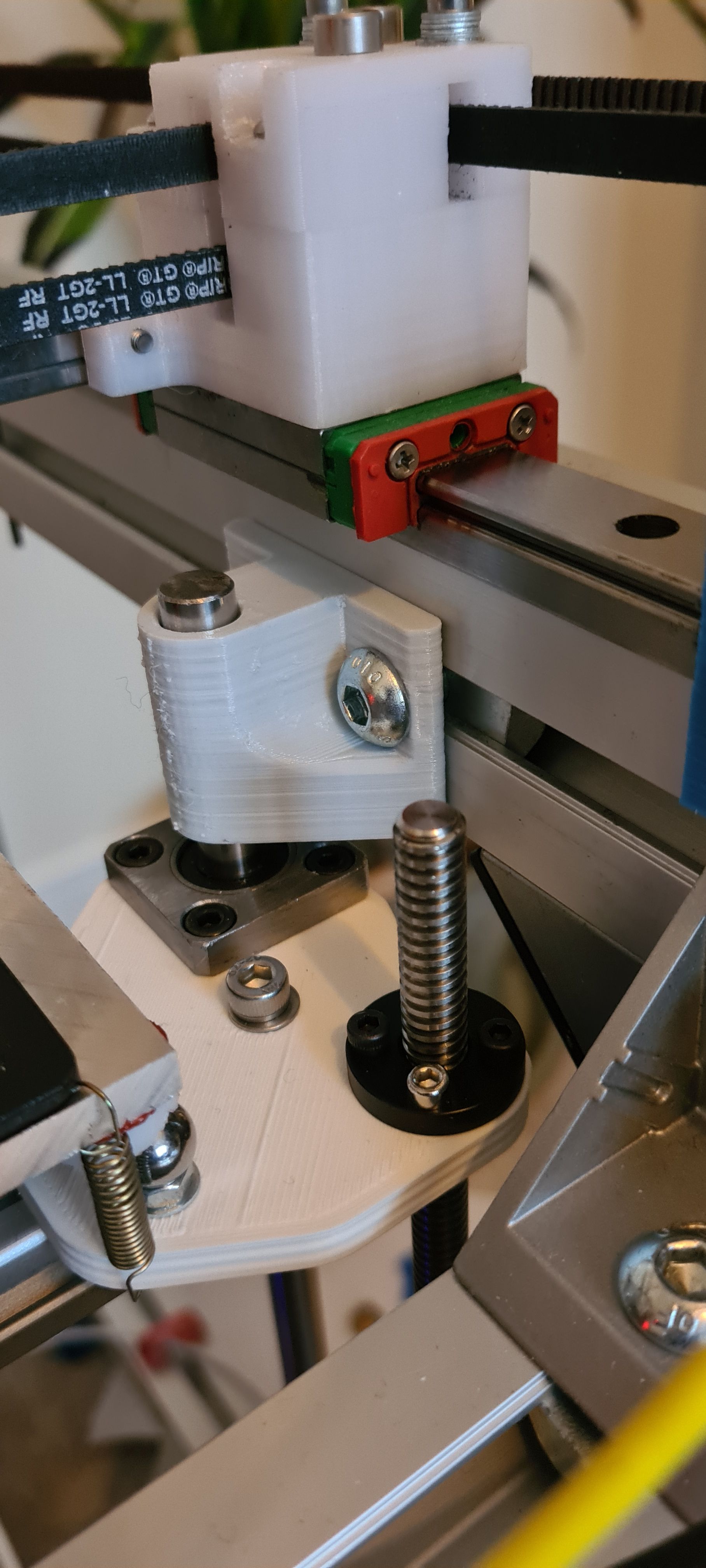
On the lubrication, I couldn't really find any info either way, but generally I'd assume not (at least the INGUS ones don't...), though I'd keep a small amount of oil on the lead screw anyway. Will see how they go after a bit of running
@zapta Interesting...Realised I mis-typed before. I'm using 8mm dia lead screws, but they're 2mm lead, 2mm pitch (so 1rev = 2mm movement). Coupled with 0.9deg motors, thats 5um per full step so I probably could afford to go for a higher lead! Guessing that the multiple starts might cancel out any off-axis-ness or be ginerally less susceptible to pitch errors?
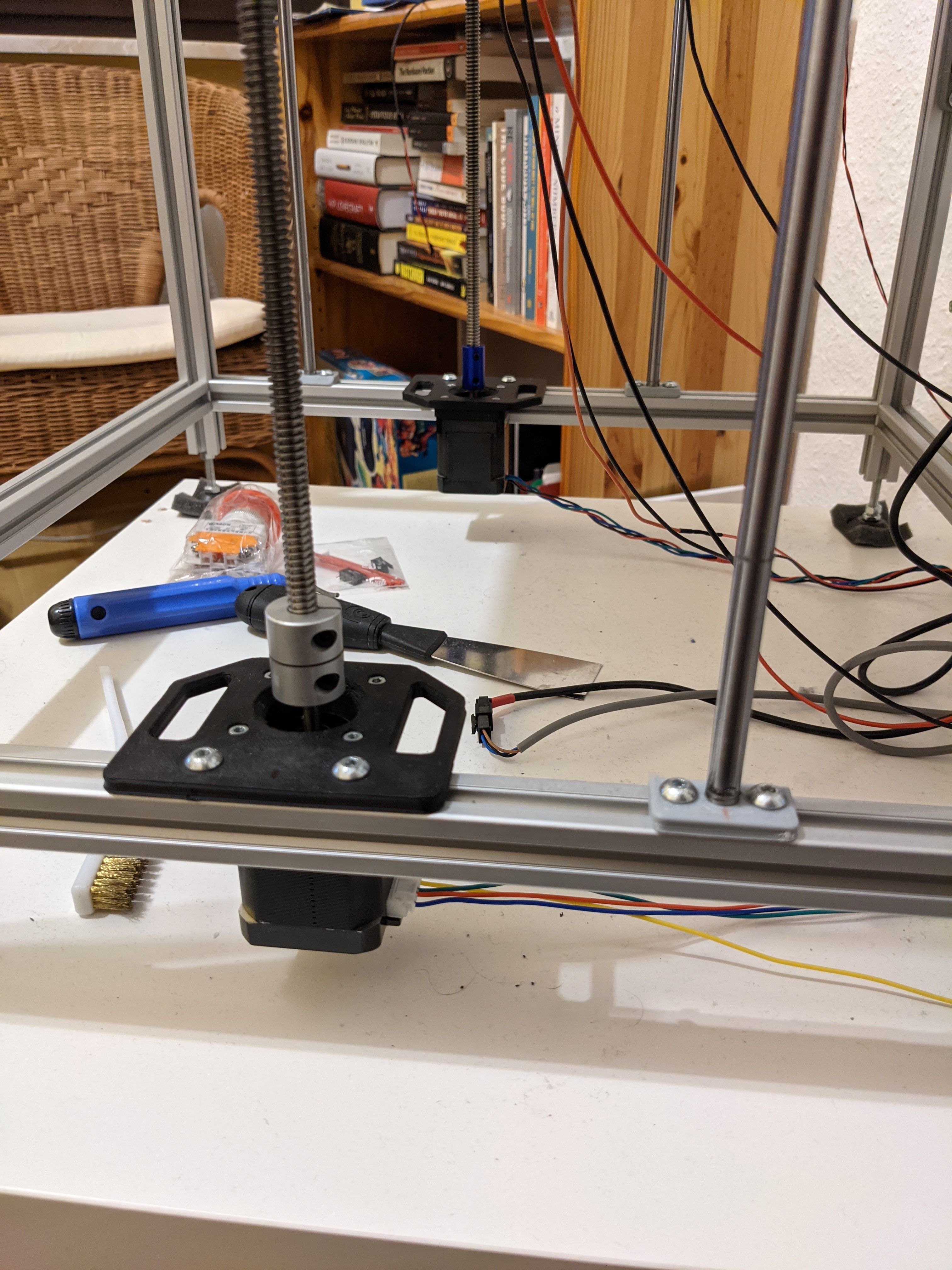
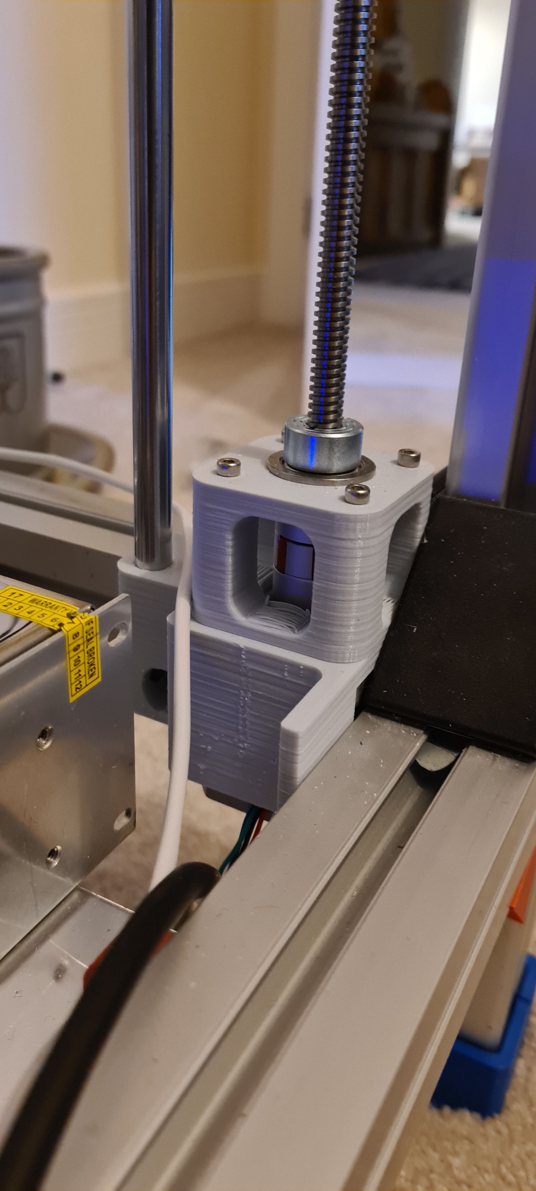
@theruttmeister / @sinned6915 Lead screws shouldn't be too overconstrained now. They've got a collar which sits on a flanged bearing at the bottom to take the weight, then a spider-type coupler to the motor underneath (3x independent motors). Might need to double-check how well the motor & flanged bearing line up as it was quite late when I assembled them
Guide-wise I've got 2x 10mm rods at the front (mounted on the left/right beams) and a single MGN15H at the back. Both the rods and the MGN15 are only mounted at the top & bottom
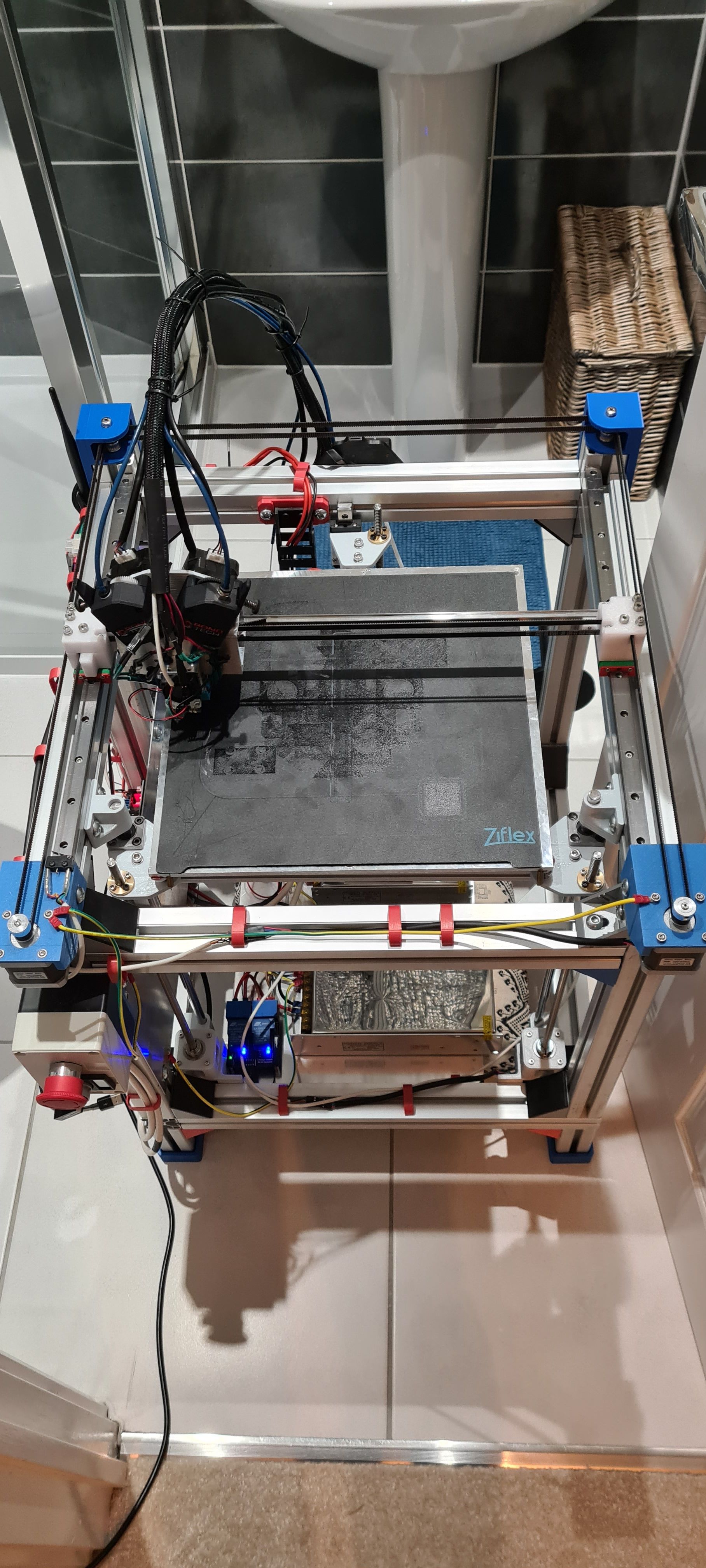
Here's a slightly better picture of the printer (from when it had the brass nuts). For a short while it lived in our spare bathroom so I could run it when working from home...
-
If you remove the nut does the leadscrew wiggle on top during rotation? If it does then that is likely the reason for z banding. Leadscrew nuts are almost never a problem nor is their clearance because they are just used for pushing up and down. After a lot of experiments I've concluded that most of info on the topic of z-banding is simply wrong and now I have a fix that works for my printers every time.
So I had these problems appearing semi randomly (because I often disassemble the printer) until I realized that due to the coupling there is sometimes a bit of wiggle which is caused by screws that tighten coupler to the leadscrew and to the motor shaft (different diameters of the leadcrew and the motor shaft don't help here). This was actually discussed on this forum so you can look up these discussions. Screws should however not affect the coupler you use as much since it clamps, however that coupler is not really built to keep the leadcrew perfectly centered and in my tests it had biggest eccentricity compared to three other types of couplers (its called elastomeric coupling after all). With rigid couplers the procedure I use now is to mess with tightening the coupler until there is no wiggle on top then just add the nut afterwards. The nuts I use are very cheap ones with huge clearance and they work just fine.
You can already notice that constraining the leadcrew is related to the couplers and over-constraining is a problem only when you use rigid coupling at the bottom that is not centered, however the coupler you use requires constraining the leadscrew preferably from both sides (you want a straight leadscrew). Just check the design of CNC machines and you will notice how these couplers are used. Note that ballscrew does not magically solve this problem but because it should have almost no play with well constrained bed it will force relatively precise movement in z axis (for 3d printer at least) even when it eccentric but its definitely a waste of money considering other solutions.
If you don't want to mess much with z axis design you can always get stepper motors with integrated leadscrews which will make the whole problem disappear. Paradoxically the price of these motors from aliexpress will almost match the price of motor + coupler + leadscrew.
The problem is definitely more visible with 2mm lead. Additionally you want to isolate all other variable i.e. do a print without heated bed, turn off bed leveling compensation, turn off z hop, have bed rails aligned and squared and so on. When solving this printing cubes close to all leadscrews plus one at the center of the build plate helps to find out which one the screws is the worst offender.
Good luck!
-
@akstrfn Agree with everything you've said there! I'm pretty confident my remaining issues are in the details of how I've put together my Z-axis and not the usual red herrings.
I am going to try aligning the motors/leadscrews/couplers better before spending more on it, but am definitely considering the rigid couplers. I had been trying to avoid putting the z-load through the motor bearings so went for the elastomeric couplers and flanged bearing approach, but the reality is over 3 motors the load is pretty small and I reckon the off axis loads from the thing being miss-aligned will do more to damage the stepper bearings anyway.
-
Just stumbled upon this video. Informative beginning and proposes an interesting magnetic Z lead screw to bed DIY coupler design.
-
@engikeneer said in Lead screw nut - brass vs POM and radial clearance/backlash:
Guessing that the multiple starts might cancel out any off-axis-ness or be ginerally less susceptible to pitch errors?
That's an interesting point. Never though of that. I wonder if having only 1 start contributed to the z banding I got.
-
@zapta said in Lead screw nut - brass vs POM and radial clearance/backlash:
Just stumbled upon this video. Informative beginning and proposes an interesting magnetic Z lead screw to bed DIY coupler design.
Yikes.
That's a very complicated way to add backlash to a ballscrew!There have been a number of printed compliant joint designs kicking around for ages, constraining things so that the motion is only planar is not that hard.
-
@zapta on second thought I think it might be less about the number of starts and more the different leads. For a given pitch error (caused by an amount of wobble, over constraint etc) which will typically occur once per rev, the impact on each layer of the print is 4x less with an 8mm lead than a 2mm lead, so each 'band' on your print is going to be 4x smaller. Also they'll be spread put more so I'm guessing they aren't as noticeable.
I have some rigid couplers arriving in the next couple of days so will try fitting them and ditching the flanged bearings. I think I also need to redesign the printed z motor mounts are they are a bit flimsy and I can see noticeable flex now I've watched them more in motion. This is where I wish I had my own cnc mill!

-
@engikeneer I've been fighting some z banding myself. My motor mount was pretty flimsy. Replaced it with an aluminum 90 degree mount secured to an extrusion. Much more rigid. That seems to have helped quite a bit.
Your comment on 2mm vs 8mm lead makes sense. I use a 1mm lead and I also wondered if some of the pattern I was seeing was due to the large amount of rotation needed by the lead screws causing the wobble to repeat more frequently.
-
@zapta said in Lead screw nut - brass vs POM and radial clearance/backlash:
Just stumbled upon this video. Informative beginning and proposes an interesting magnetic Z lead screw to bed DIY coupler design.
The video is uh oh and it hurts a bit... You gotta love when people play engineering and put "requirements" which in this case boil down to "my requirements are to use ballscrew" -> find justification hard. Steel leadscrews don't not last long enough is he like serious... Is it so hard to learn from e.g. prusa or creality?
Why buy a motor with integrated leadscrew from aliexpress for 10eur (15eur delivered) when I can pay 20eur for ballscrew that does not work? On occasions you can get these motors from amazon for 20-30eur prime (but mostly 8mm lead).
@engikeneer @Phaedrux too much flimsiness for sure does not help if you create lever like force on top however it might not be as bad as you think. Let me show you setup that works without a problem once I made sure that rotation is centric:

5mm ABS... As flimsy as gets, however no z-banding present... One body aluminum coupler is what ender uses and I can not recommend it enough, its very clever way of doing more with less.
The point is that if bed movement is well constrained you can not really expect the problem to come from lateral movement of the screw pushing it around so what needs to be happening is that there is repetitive non linear movement in z-axis i.e. z-axis is first being lifted more in one part of the rotation then less in the other part of the rotation which causes compression of certain set of layers and stretching of others.
While you might not notice this problem visually on 8mm lead do measure the height of different objects and if you have the problem described above you will get non linear change of heights that does not match desired print height. I had height precision issue for a very long time on my ender until fixing the leadscrew...
-

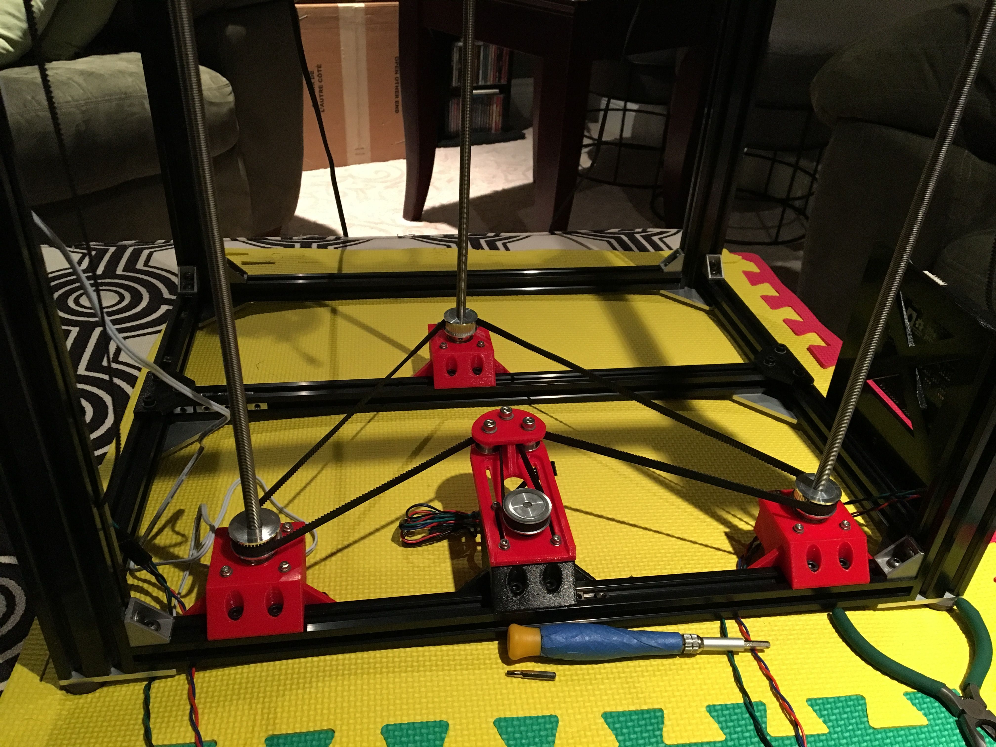
Originally it was a plastic motor mount and tensioner like this.
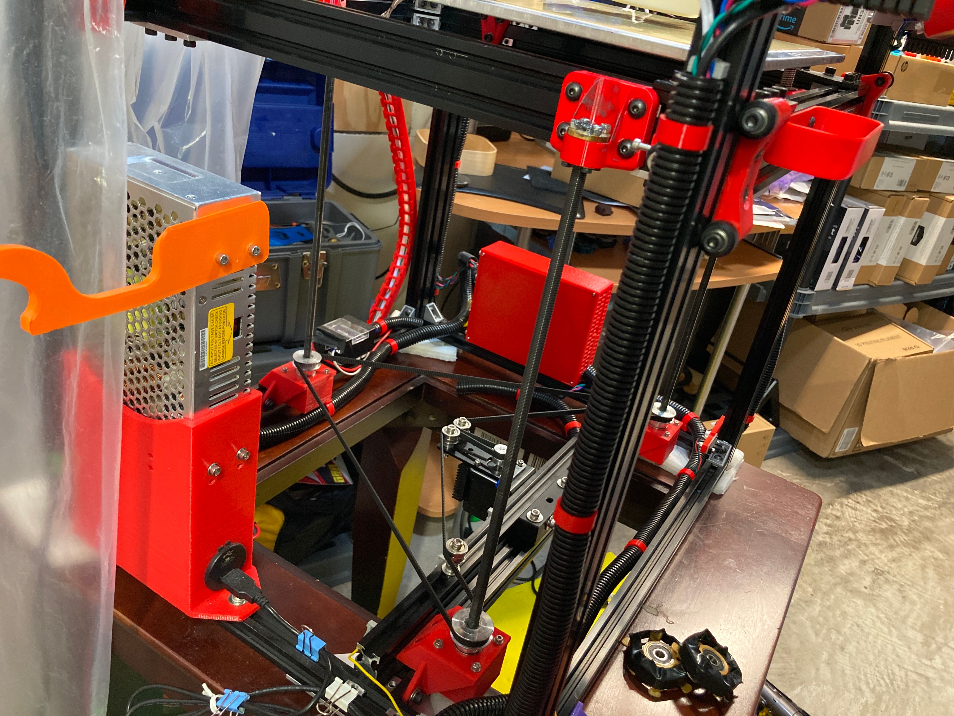
Since changed to this.

-
@Phaedrux very fancy setup although I would put pulleys below the bearing. Do you have some picture of the assembly of leadscrew bearing system? I guess you are using duet so I'm curious whats the reason for single motor drive?
For z-banding you mentioned did you test without z-hop?
-
@akstrfn yes single motor for simplicity. No duex when I started with it. The bed is stable and has a 3 point leveling screws. So no problem there.
The lead screw mounts are a double bearing block with a collar above and below. It was a bit tricky getting it aligned with the bed mounts. It was designed on the fly rather than in CAD. Not recommended.
No z hop.
-
@Phaedrux I'm thinking of doing 3Z similar to your setup but driven by 3 motors since I can use spare extruder motor on duet 2 for third motor. But as you mention the bed does not go out of level so often hence not really motivated to mess with it for now just for autoleveling