New to Duet but heading to a major project. Advise needed.
-
New data provided by the guys at SMC in the attempt to make it work DUET 1XD with their LECPAP driver. They said that it seems that the electronic card is compatible BUT...
I don't understand all the connection equivalences between 1XD board and this driver.
They said:
What you will have to confirm in order to work with our LECPA driver are several aspects:
- The Duet 1XD board has a PTO (Pulse Train Output) output. PWM is invalid.
- That works at 5 Vdc / 24 Vdc, differential mode / open collector mode
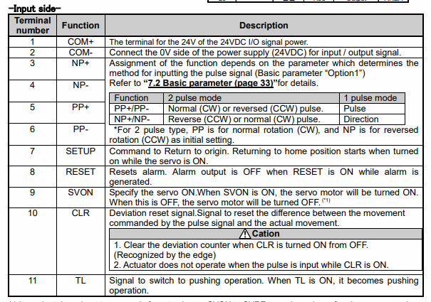
- They will need digital control I / O. Necessary outputs (which are inputs to the driver) SVON (necessary, to give torque to the motor), SETUP (necessary, to reference the axis), INP (to know that the movement has finished) ... and certain inputs (outputs of our driver) of confirmations.
These are the inputs and outputs that you have to be taken into account:
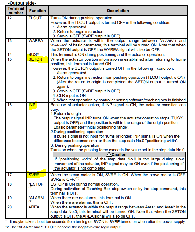
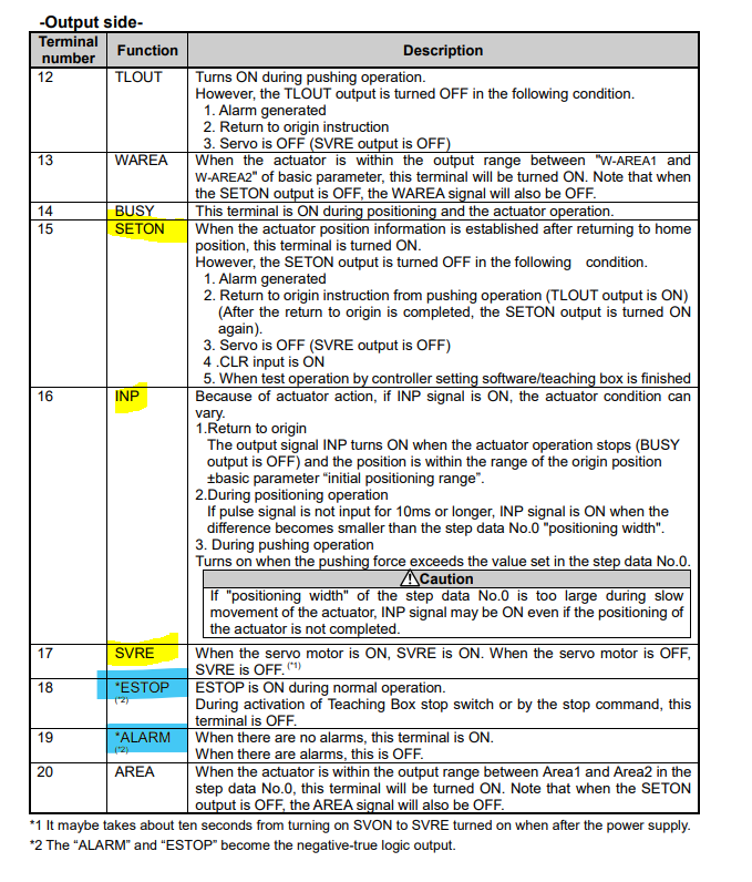
Regarding the outputs, I think it is important that they have SETON, INP and SVRE to have a confirmation of when there is torque in the motor, the referenced axis and the signal that the movement has been carried out:
Schemes depending on the working mode (pulse output mode):

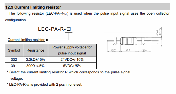
It is important to put the corresponding resistance depending on whether they work at 24 V or 5 V, otherwise the driver would break:
So my doubts and fear lie in the equivalence of the signals.
DIR and STEP are clear, but where do I connect the ENABLE?
I could connect SETON, INP and SVRE to io0.out, io2.out, but I am missing one.
Out0 and out1 I interpret that they are not digital outputs.
Reset to reset, I also have it clear.And where go the rest of the pins?
This is a sketch (and dirty) schematic for all the boards involved:

Any ideas, before blue smoke?

-
I'm afraid we are going to abandon the idea of using 1XD boards with SMC drivers.
This afternoon I have been speaking with a technical advisor from SMC, and although it might think could be possible to make it work, it is much more difficult than it initially seemed.
The digital signals of their driver works at 24V, so I would have to pass each of the pins through relays to increase the voltage from 5v to 24v. It would be necessary to add resistors in each pin to limit the current in the DIR and STEP signals. In addition, we would not have enough input and output pins in the 1XD to fully control the digital driver's functions. And this is their most simple driver.
I think the SMC proposal is too professional solution to be controlled outside of industrial PLCs. It's a shame because the prices are great and the quality is top, excellent.Instead, we will use normal stepper motors, controlled from the 6HC and the toolboards, sized for the weight and speed required for the machine (XY nema23, Z's and E's nema17). And trial-error as on other occasions.

Alternatively we could try "more" normal servos such as JMC iHSV57-30-18-36 and the 1XD bords, since I have seen that someone has already used them successfully with DUET,
but: would we have the disadvantage of having to use limit switches and lose sensorless if we use this? Correct? I'm pretty sure there is, because it isn't feedback from the servo. It would be a step backwards.We will therefore use a 6HC board, plus a distribution board and three toolboards. Simpler, and less ambitious. I hope it would be good enough choice.
I'm sorry but If I have any questions, don't worry, I'll ask you.


Regards,
-
@Marcossf said in New to Duet but heading to a major project. Advise needed.:
I'm afraid we are going to abandon the idea of using 1XD boards with SMC drivers.
This afternoon I have been speaking with a technical advisor from SMC, and although it might think could be possible to make it work, it is much more difficult than it initially seemed.
The digital signals of their driver works at 24V, so I would have to pass each of the pins through relays to increase the voltage from 5v to 24v. It would be necessary to add resistors in each pin to limit the current in the DIR and STEP signals.their datasheet states that it can be driven from 5v or 24v , why do you need to increase voltage?
-
@hackinistrator Their technician is what he told us.
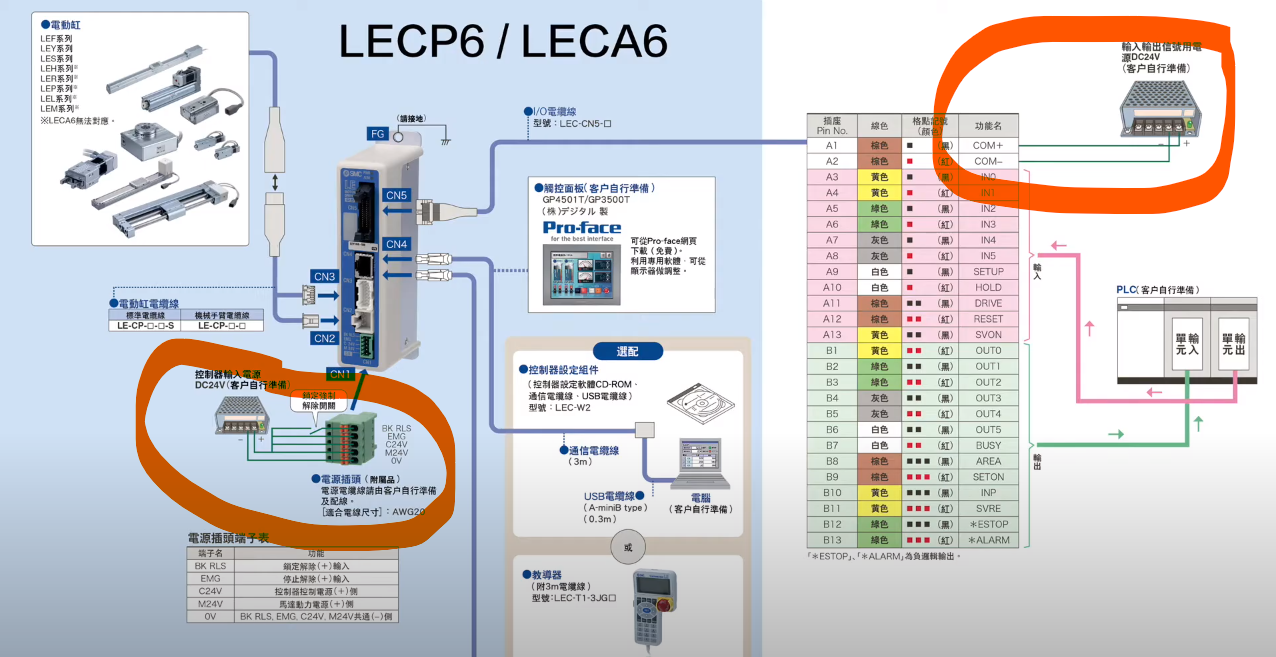
It seemed strange to me, but the only thing that would work at 5V would be the DIR and STEP, and even so, you would have to put a 390 Ohm resistor as a voltage limiter for the pulses.As you can see in the diagram below, all the I/O control pins on SMC driver are powered on 24v.
The other limitation we saw is that there are not enough pins to be able to use the 1XD board. We need at least SETUP, SVON, CLR, SETON, INP, SVRE, ESTOP, ALARM. Also their driver do not use EN because that state is controlled from SVON and SVRE, I understand that they are equivalent in terms of functionality, but they have conditionals behind this logic and they are not a simple enable or disable the engine as in a "normal" external driver (STEP , DIR, ENABLE).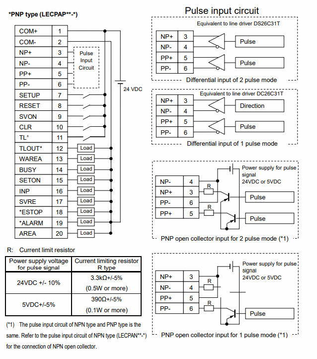
The alternative they offer us is to pass all the movement signals through an intermediate PCL controlled by ModBus or serial, but it is a way of complicating something that is already going to be complex.
Perhaps, as @dc42 commented somewhere in this forum, in the next version of this 1XD board, this type of servos, encoders and industrial automation elements may been supported.
At this moment, I am afraid that we have to go down a notch, and settle for another more mundane solution. -
If the signal levels are 24V then it sounds to me that those servo drives are intended for use with PLCs.
Duet WiFi hardware designer and firmware engineer
Please do not ask me for Duet support via PM or email, use the forum
http://www.escher3d.com, https://miscsolutions.wordpress.com -
@dc42 Yes, I intended to use industrial automation elements that are meant to be used with PLC controllers.
Perhaps could program a PLC controller to accept Duet commands. But this would be a totally different project. -
@Marcossf how many other signals do you need to control on the drivers (that are at 24V?)
Also it would be worth looking at alternative drivers that work with 5V signal levels.
-
@Marcossf I took a look at the manual for your stepper drivers and you certainly CAN use all the control signals at 5 Volts.
Signals sent to the controller go into LEDs, so you the 390 Ohm resistor is there to keep the LED from burning out due to overcurrent. That's the standard way to allow the user of the controller to select whatever voltage they desire to control the equipment.
Signals that come out of the controller are open-collector transistors, and you can choose what voltage is applied to the transistor. That's also the standard way to provide an interface that supports different voltage needs.
Ask the representative from the company if you can supply 5 Volts to COM1+ They should say Yes. If they do not, I would highly recommend first asking to try a different representative and if that fails, I guess you need to look for a different stepper controller company.
-
@alankilian said in New to Duet but heading to a major project. Advise needed.:
@Marcossf I took a look at the manual for your stepper drivers and you certainly CAN use all the control signals at 5 Volts.
COM1+ input must be 24V. It is the power supply for the motor and also common for the driver supply. NP and PP (pulse and direction) accept the signal at 5v, but not all other I/Os
Initially this is what I thought, until I spoke with the support technician at SMC Spain and he confirmed that the I/O signals are at the same voltage as the power supply (24v).
The DIR and STEP signals are the only ones that admit 5V through an external circuit with the corresponding limiting resistors.My intention was to be able to use these drivers with ENA, DIR and STEP on the 1XD board and for the integrated closed loop part to be managed by the driver itself, with the home signal apart, but that's all. To which they replied that it is not possible.
I have looked at the Thomson Linear and the Yamaha Transervo, and from what I see in their driver info, the signals and voltage are the same as the SMC driver. It appears to be the standard control for industrial PLC servos/steppers.
@T3P3Tony said in New to Duet but heading to a major project. Advise needed.:
how many other signals do you need to control on the drivers (that are at 24V?)
Also it would be worth looking at alternative drivers that work with 5V signal levels.
Yellow mandatoy, blue recommended but optional:
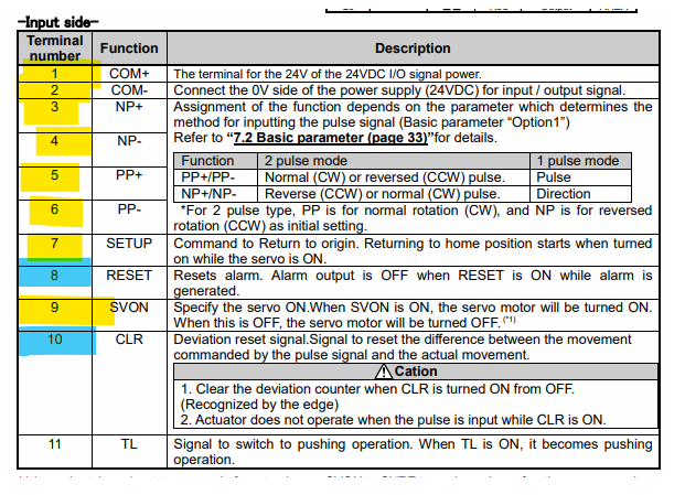
For SMC drivers, a minimum of 8 I/O signals are required. Unfortunately SMC does not allow controlling its linear actuators with other brands drivers.
I'm starting to look for alternatives with a similar form factor that can be more easily controlled, but I don't like what I find so far (poor support, no warranty, lack of approvals).
I'll keep searching. Thanks to both.
-
If your contact is telling you COM1+ on CN5 is the power supply for the motor, you still need to get in touch with someone more knowledgeable at their company.
COM1+ Is not the power for the motors.
Motor power is supplied via M24V on connector CN1 according to the document you linked to in your first posting.If these folks built a 24-Volt only controller you don't want to work with them anyway.
-
@alankilian said in New to Duet but heading to a major project. Advise needed.:
If your contact is telling you COM1+ on CN5 is the power supply for the motor, you still need to get in touch with someone more knowledgeable at their company.
COM1+ Is not the power for the motors.
Motor power is supplied via M24V on connector CN1 according to the document you linked to in your first posting.If these folks built a 24-Volt only controller you don't want to work with them anyway.
Ok, I understand what you mean, but it seems to me that there's a confusion somewhere.
Obviously the motor and driver main supply are in CN1. It may not explain me well, my fault.
However, in CN5, which is the connector that has to be wired to the Duet 1XD, pin 1-COM + is powered at + 24v, and internally also powers the I/O pins of the driver, except ±NP and ±PP.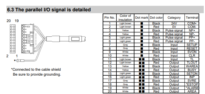
It is not like this? How would you connect it according to your suggestion to the Duet board? Do you still think it is possible?
I do not rule out that the SMC technician could have no idea, what it may be, or that I am not interpreting the data correctly.
-
I found this other schematic that draws two power supplies. It is true that I don't understand what the source connected to COM+ uses for.
I'll ask for clarification asap.
-
You'll have independent z-axes? I was building a machine like this in the past. Here is a relevant thread for dealing with the different z-axes offsets. It worked well enough.
https://forum.duet3d.com/topic/18051/printer-with-two-independent-z-axes-how-to-synchronize
-
If you want to use this device and follow the instructions of your technician, you can build a pretty simple board that converts all the signals you need.
Or you can buy some existing boards to convert the levels for you.
I would recommend just buying the level translator boards you need and wire them up.
-
If possible i would avoid having two sets of optocouplers in the system (from Duet 3.3V/5V signals ->24V and then from 24V on the input to the servo logic) each optocoupler increases the delay which reduces your maximum step rate. and increases direction hold time.
look for fast level shifting options, either off the shelf of you can make a custom board.
-
Okay, signal conversion would work, but still there aren't enough I/O pins on the 1XD board to control all the signals received from the servo.
I'd better get other solutions like Oriental Motors or Clearpath with closed loop servos but only using DIR / STEP signals. SMC drivers seem too advanced for this controller. We won't to unnecessarily complicate the machine just by wanting use certain HW.
-
I think we've found a feasible alternative to SMC drivers.
It's from OrientalMotors, and it is their AZD-K controller:
http://www.orientalmotor.eu/msites/az/en/
It has internal closed loop with absolute encoder BUT can be controlled just with 4 signals, STEP and DIR at 5V_10mA, and apparently without using additional control pin. The closed loop position correction it's done internally in the driver controller.
I'll ask them for a demo unit, to see if can work with Duet 1XD board.
I have the doubt of how to homing the axes with this configuration. It is assumed that a G28 XO Y0 Zxxx could also be sent and as it already know where its absolute origin is, it would be positioned at zeroes before being able to move to print, although the Duet does not have real position feedback.
What do you think about? It' would work?
-
if its not a secret , can you tell what are you trying to extrude that needs those overkill actuators and servos , for such a small printing volume (200x200x100) ?
-
Microdosing of drugs and biochemicals. And other things like inkjet heads, spectrographs in the future ...
-
@Marcossf any reason not to use homing on the Duet using standard endstops? move an axis to a limit whith and endstop trigger - that position is then known by the Duet (at whatever the limit is set in firmware) then proceed from there. The "absolute" psotion read internally by the servo and used for closed loop control does not need to match the position the Duet is using.